

Page 1
SD Advanced
Installation and
Operation Guide
Page 2

Dedicated Micros ©2009
2
SD Advanced
Whilst every attempt is made to ensure these manuals are accurate and current, Dedicated Micros reserve the right to alter or
modify the specication of the machine described herein without prejudice.
Contents
Introduction ........................................................................... 3
Features ............................................................................... 4
Important Safeguards ........................................................... 6
Installing the Unit .................................................................. 8
Installation .......................................................................... 10
Conguring the Unit ............................................................ 18
Remote Control .................................................................. 20
Main Menu .......................................................................... 22
Navigating The Conguration Menus .................................23
System Settings.................................................................. 26
Display Settings .................................................................. 41
Camera Settings ................................................................. 50
Record Settings .................................................................. 55
Alarm Settings ......................................................................... 67
Network Settings ................................................................ 82
Analytics & Text .................................................................. 92
Oracle Dome Conguration ................................................ 98
Unit Operation .................................................................. 110
Appendix A........................................................................ 130
Appendix B ....................................................................... 131
Appendix C ....................................................................... 133
Appendix D ...................................................................... 134
Appendix E ....................................................................... 135
Page 3

Dedicated Micros ©2009
3
SD Advanced
Introduction
What is the…
SD Advanced ?
A comprehensive digital recording solution, the SD Advanced is a stand-alone high performance
recording system offering reliable, networked, scalable CCTV at an affordable price.
Its size and design make it the ideal desktop solution and perfect for installations were high record
rates and network capabilities are required.
Dedicated Micros renowned MultiMode record feature enables an operator to set different recording
rates, resolution and compression formats across scheduled, normal and alarm modes for each
individual camera. Offering either JPEG or MPEG-4 recording, the SD Advanced provides the user
with both high quality video images and minimum storage consumption.
Available with 8, 12 or 16 camera inputs, all offering telemetry control, the SD Advanced has built in
Alarm functionality and onboard Activity detection software.
To give operators maximum viewing exibility, the unit can be congured to contain a mixture of spot
or main monitor outputs. Camera channels can be viewed in single or multi-screen mode on a local
monitor or remotely over an IP connection.
The accompanying Infra-Red (IR) Remote Control has a colour coded ‘Softkey’ interface with
conguration menus common to both local monitor and web pages, making for easy set-up and
operation. The front panel interface also allows for easy operation when viewing on a local monitor.
The SD Advanced includes as standard internal storage with an integrated CD/DVD Re-Writer and
USB ports / eSATA connections for external video archiving.
The unit also offers integrated text support, allowing users to connect with cash registers in retail
applications to monitor Point Of Sale (POS) locations. Capturing and associating video with the
relevant text information allows the user to search video footage by time, event, and text data to
provide evidence of fraud or to aid identication of regular offenders.
Among the many other features included as standard on the SD Advanced are; multiway display and
remote monitoring using NetVu ObserVer (using DM’s unique TransCoding capabilities to provide
uent live and replay images).
With telemetry control of up to 16 cameras (including coax telemetry), control of dome cameras,
I.P camera support , audio recording, activity detection plus many more exciting features; the SD
Advanced is the ideal product when high performance video recording and transmission is required
at an affordable cost.
For further information, please visit the website:
www.dedicatedmicros.com
or contact customer services in your region.
Page 4

Dedicated Micros ©2009
4
SD Advanced
Features
• 8, 12 or 16 camera input options
• Field serviceable hard drives
• Telemetry support (Coax & Serial)
• All DVR functions fully supported by Keyboard/IR Remote Control/Front Panel
• Scalable recording settings
•
MultiMode Recording - Dynamically-switchable resolution, record-rate & compression
(MPEG4/JPEG) per camera
• JPEG or MPEG-4 recording and transmission
• Up to 3TB of on-board storage
• I.P Camera support
• Web pages provide easy remote conguration
• Single, Picture in Picture and Multiway displays
• Live and playback viewing locally and over Ethernet
• Built in activity detection
• On-board Help videos
• Built in DVD-R writer and USB ports for download of video archive to external
ash memory
•
Point&go telemetry control and Absolute Positioning
• Alarm Inputs & Outputs
• Easy to use on-screen, colour coded soft keys
• Front panel interface
• Text support and text search features ideal for retail installations
• Optional external keyboard available
• Conguration via USB mouse and USB QWERTY keyboard
• BS8418 compliant
The unit has NetVu Connected technology built-in to ensure maximum compatibility with future
developments in networked security. NetVu Connected technology enables the Unit to fully interact
with other NetVu Connected compatible products from Dedicated Micros including the DV-IP
Decoder, NetVu ObserVer and PDA Viewers. Providing interoperability between the worlds leading
security companies, NetVu Connected uses industry standard networking protocols supported by a
wide range of third party integration products and SDKs to ensure future on-going compatibility.
COMMON CONFIGURATION INTERFACE
A Common Conguration interface is displayed when the unit’s conguration screens are accessed
locally at the unit or remotely via a web browser. This unied system ensures that the installer is
familiar with the conguration screens irrespective of their location to the unit, minimising training
and familiarisation time and increasing the speed of installation and alteration.
The Unit includes a unique colour-coded menu structure and onscreen Graphical User Interface
(GUI). Context sensitive, the menu structure always represents the area of the menu the user is in,
allowing them to quickly select the options and settings they need without having to trawl through
menu pages and options. The colour coded buttons displayed on the monitor match those on the IR
Remote Control, whilst control can also be conducted through an attached USB Mouse or supported
Keyboard (DM/KBC1 / DM/KBC2).
Page 5

Dedicated Micros ©2009
5
SD Advanced
Point&go provides the user with easy to use, fast, accurate telemetry control via an attached
monitor. With no need for a telemetry keyboard, users are able to use Pan & Tilt control of a
Dedicated Micros Oracle Dome simply by clicking an area of the monitor. The camera will instantly
respond, positioning the selected area in the middle of the screen, ideal for tracking movement
through a scene.
MAP
Users can now navigate around their CCTV installation using a graphical map. Selecting the
relevant camera from the map will instantly connect the user to that cameras image stream. With the
ability to load bespoke map images and oor plans to reect their installations, the Maps feature is
ideal for quickly identifying camera locations around a site or CCTV network.
Design of the manual
The manual has three parts:
1. Installation Shows details of how to install the unit and connect external devices.
2. Conguration Shows details of the unit’s menus.
3. Operation Shows quick reference details on how to control the unit.
The order and layout of these pages has been designed to help the setup process. It is
recommended that the menus are edited sequentially (as they appear on the page), to enable
accurate, easy and efcient setup.
Page 6
Dedicated Micros ©2009
6
SD Advanced
Important Safeguards
Read Instructions
All the safety and operating instructions should be read before the unit is operated.
Power Sources
This unit should be operated only from the type of power source indicated on the manufacturer’s
label.
Servicing
Do not attempt to service this unit yourself as opening or removing covers may expose you to
dangerous voltage or other hazards.
Refer all servicing to qualied service personnel.
Ventilation
Ensure unit is properly ventilated to protect from overheating.
All the safety and operating instructions should be read before the unit is operated.
To prevent re or shock hazard, do not expose this equipment to rain or moisture. The lightning ash
with arrowhead symbol within an equilateral triangle is intended to alert the user of this equipment
that there are dangerous voltages within the enclosure which may be of sufcient magnitude to
constitute a risk of electric shock.
This is a class A product. In a domestic environment this product may cause radio interference in
which case the user may be required to take adequate measures.
Lightning Strike
The unit has some inbuilt protection for lightning strike, however it is recommended that isolation
transformers be tted to the system in areas where lightning is a common occurrence.
Regulatory Notes and FCC and DOC Information
(USA and Canadian Models Only)
Warning: This equipment has been tested and found to comply with the limits for a Class A digital
device, pursuant to part 15 of the FCC rules. These limits are designed to provide reasonable
protection against harmful interference when the equipment is operated in a commercial
environment. This equipment generates, uses, and can radiate radio frequency energy and, if not
installed and used in accordance with the instruction manual, may cause harmful interference to
radio communications. Operation of this equipment in a residential area is likely to cause harmful
interference in which case the user will be required to correct the interference at their own expense.
If necessary, the user should consult the dealer or an experienced radio/television technician for
corrective action. The user may nd the following booklet prepared by the Federal Communications
Commission helpful: “How to Identify and Resolve Radio-TV Interference Problems”.
This booklet is available from the US Government Printing Ofce, Washington, DC20402,
Stock No. 004-000-00345-4.
This reminder is provided to call the CCTV system installer’s attention to Art. 820-40 of the NEC that
provides guidelines for proper grounding and, in particular, species that the cable ground shall be
connected to the grounding system of the building, as close to the point of cable entry as practical.
Page 7

Dedicated Micros ©2009
7
SD Advanced
CE Mark
If this product is marked with the CE symbol it indicates compliance with all applicable directives.
Directive 89/336/EEC.
A ‘Declaration of Conformity’ is held at Dedicated Micros Ltd.,
1200 Daresbury Park, Daresbury, Cheshire, WA4 4HS, UK.
Laser
The unit supports an integrated CD writer, the following are additional warnings associated with
installing and operating the CD writer, please pay particular attention to this information.
• Caution - Use of controls or adjustments or performance of procedures other than those
specied herein may result in hazardous radiation exposure.
• To prevent exposure to laser emanations (harmful to the eyes), do not attempt to
disassemble this unit.
Page 8

Dedicated Micros ©2009
8
SD Advanced
Installing the Unit
Before you start
Check the contents of the box
The following items are included in the box:
Remove all items from the packaging and check the items listed below are present.
• SD Advanced DVR (either 8, 12 or 16 input)
• IR Remote Control (x 2)
• Power Leads
• IR Extender Lead
• SD Advanced Software/Documentation CD
• Mouse
• Rack Mounting brackets
• RS485 Telemetry Adaptor
• Quick Start Guide
If any of these items are missing please contact Dedicated Micros Technical Support team.
Note: Before installing the SD Advanced DVR, carefully read all Safety Instructions and the
following information on where the unit should be located.
Choosing a location for installation
• The SD Advanced is designed to be desk, shelf or rack mounted. Rack mounting
brackets are available as an optional accessory.
• Ensure the SD Advanced unit is properly ventilated to protect from overheating.
• Ensure there is a 3cm gap on both sides of the unit.
• Ensure the IR receiver on the front of the unit faces the operator position, and is not
more than 10 feet (3 metres) from the operator. An IR Remote Control Extender is also
available.
• Ensure the unit is not located anywhere it could be subject to mechanical shocks.
• The unit should be located in an area with low humidity and a minimum of dust. Avoid
places like damp basements or loft spaces.
• If the unit is to be installed in a closed assembly, the maximum operating temperature
must not exceed 40°C (104°F).
• Ensure there is reliable earthing of the mains outlet when tted to supply connections
(other than direct connection to the branch circuit).
• Any branch circuit supplying the unit must be rated at 15Amps.
• It is recommended that an uninteruptable power source be connected to the unit in
case of power failure (to ensure continuous operation of the unit).
Page 9

Dedicated Micros ©2009
9
SD Advanced
Electrical Connections
Please ensure the following are available and have been tested prior to the installation:
• Mains point
• Network point
• Network cable
• Active video signals i.e. at least one working camera feed
• PC with CD ROM drive and connection to the same network as the DVR
(Recommended).
Quick Overview of SD Advanced Record Settings
The SD Advanced provides as default:
High performance recording on ALL cameras with minimal conguration.
Consistent recording duration and smooth motion video per camera regardless of the number of
cameras.
Default record settings at MPEG4 6pps (at 2CIF), JPEG 3pps (at 2CIF) and MultiMode recording at
MPEG4 6pps (at 2CIF), JPEG 6pps (at 2CIF).
Pre-congured up to 14, 30, 45, 60 or 90 days storage settings (dependant on model).
Complete Flexibility
The advanced record menu can be used to congure individual cameras to suit specic
requirements e.g. Entry/Exit routes. Various storage sizes are available dependant on the
combination of the number of cameras, the storage options and record rates selected.
Note:
It is the Installer/Owner’s responsibility to ensure that the record duration is set to the
necessary requirements of the application.
MultiMode Recording
The unit supports MultiMode recording, which is a storage technology developed by Dedicated
Micros. This offers the ability to set different recording rates, resolutions and compression formats
across scheduled, normal and alarm modes for each individual camera.
By varying the quality, bit rate and le size of the recorded images, the MultiMode function can
increase recording capabilities of the unit.
MultiMode offers:
Ability to set different recording resolutions.
Ability to set and switch MPEG or JPEG compression recording as required.
Ability to set PPS recording rate per camera.
Dynamically switchable resolution when switching from Normal to Event recording.
Dynamically switchable compression between MPEG4 and JPEG from Normal to
Event recording.
Page 10

Dedicated Micros ©2009
10
SD Advanced
Installation
Front Panel connections
Data
DVD-R Internal DVD-R drive (located under hinged ap)
USB USB2.0 connector (located under hinged ap)
LED Green - Unit working normally
No LED - Power Failure
Live - Unit is in Live mode when lit.
Play -Unit is in Playback mode when lit.
Spot - Spot (MON B) monitor is being controlled
Record - Unit is recording video to the internal hard disk.
Rear Panel connections
16 Input model
12 Input model
8 Input model
Page 11

Dedicated Micros ©2009
11
SD Advanced
Video
8. 12 & 16 way units
VID1 to VID8/VID12/VID16 75Ω BNC composite video input, 1V pk-pk with loop through
MON A 75Ω BNC composite monitor output, 1V pk-pk
MON B Spot Monitor output
MON A S Video Connection
VGA D-type connection for VGA monitors
Audio
Audio IN (Dual) RCA (phono) socket, 8KHz/16KHz/22KHz sampling 75Ω input
impedance, 1V pk-pk
Audio OUT (Dual) RCA (phono) socket, line level <100Ω output impedance,1V pk-
pk amplication required
Data
SERIAL 1 RS-232 (3 wire & 9 wire)
SERIAL 2 RS-232 (3 wire & 9 wire)
SERIAL 3 (PTZ) RS-485 (2 wire & 4 wire)
SERIAL 4 (PTZ) RS-485 (2 wire & 4 wire)
USB 2x USB2.0 connectors
IR Infra-Red Input connector for IR Remote Control Extender
NET RJ45 Ethernet network connector, 10/100 Mb/s Ethernet Network
KBD RJ12 connector for use with Dedicated Micros telemetry
keyboards (KBC1, KBC2)
EXP RJ12 expansion port for future use
SATA E-Sata port available for storage expansion
Alarms and relays
ALARMS IN Via 25-way (female) D Type 24V 200mA
20 general alarm inputs
Range of Alarm states are:
i. 0 – 800R = Short circuit
ii. 800R – 2K = closed contact
iii. 2k – 12k = open contact
iv. > 12K = open circuit
RELAYS Via 9-way (female) D Type rated at 24V 200mA
4 onboard light duty relay output (500mA@ 12V-48V Max)
Power
POWER IEC mains power socket & switch
Page 12

Dedicated Micros ©2009
12
SD Advanced
Installing the SD Advanced Unit
This procedure shows the sixteen camera input version.
Step 1 Connecting Video
The SD Advanced supports up to 4, 8, 12, 16 or 32 connected Video Inputs (dependant on model)
via the 75Ω BNC connectors. Connect cameras to the video inputs, starting from input 1.
5.12
Step 2 Monitor
The SD Advanced supports a main monitor via BNC ‘A’ and a spot monitor via BNC ‘B’.
A main monitor can also be connected via the VGA socket. If required, both the BNC ‘A’ connector
and the VGA socket can be utilised simultaneously.
Page 13

Dedicated Micros ©2009
13
SD Advanced
Step 3 Connecting Audio
The SD Advanced supports two channels of bi-directional audio, accessible through NetVu
ObserVer. Connect the audio equipment to the phono sockets AUDIO IN and AUDIO OUT. The
audio channel defaults to recording camera 1.
The following modes of operation are supported:
• Challenge – intruders from an RVRC.
• Listen – to local audio from a site at the RVRC.
• Record - local audio from a site with the video.
• Replay - all audio through a local Audio output (not supported when
Audio out is used as a challenge/PA source).
Note: The Audio output can be congured as a challenge output or as a replay output.
Step 4 Connecting to the Network
The unit supports a 10/100Mbps auto-detecting network port. Use a CAT5 cable to connect the unit
to the network.
By default the unit is congured for DHCP i.e. the unit is automatically allocated an IP address from
a network DHCP server.
Page 14

Dedicated Micros ©2009
14
SD Advanced
DHCP works by assigning an IP address at initial connection to the network. It is possible however
that this IP address can change without notication i.e. following power failure. It is therefore
recommended that the unit be allocated a xed IP address. A xed IP address can be assigned via
the Conguration Menu pages:Network Settings->Network->IP Address.
When the unit is powered up, the network address can be found by viewing on a local monitor and
navigating to Conguration Menu pages:System Settings->System->IP Address.
Refer to ‘Conguring The Unit’ for further guidance on locating the unit’s IP address and for details of
the default DNS (Domain Name Server) address.
DNS (Dynamic Name Servers) is supported and therefore the unit can be assigned a name. This
removes the need for the unit to have a xed IP address and makes it easier for a remote user to
locate.
Step 5 Relays
The SD Advanced supports up to four 24V 200mA relays.
Relay Connector
Pins Connection
1 & 6 Relay 1 signal
2 & 7 Relay 2 signal
3 & 8 Relay 3 signal
4 & 9 Relay 4 signal
Step 6 Alarms
Page 15

Dedicated Micros ©2009
15
SD Advanced
The SD Advanced supports 20 normally open/closed tamper proof alarm inputs, or one Global
keyswitch input with camera specic inputs congurable as entry/exit alarms. The alarms support
tamper proof detection using 1k in line and 5K end of line resistance. The unit detects short circuit,
open circuit and contact closure. This functionality is part of the advanced alarms supported on
NetVu Connected products and includes features required for Central Monitoring. It is compatible
with the British Standard BS8418.
Relay Connector
Pin Alarm Input Connection
1 - 20 1-20
21-25 Earth Common
End Of Line Circuitry
The following describes the EOL tamper alarms circuitry needed when EOL has been congured.
There should be two resistive values within the tamper alarm circuitry. These must be located inside
the alarm device (furthest point from the unit).
The alarm state could be Normally Open or Normally closed however the tamper states are the
same for both settings.
Open, the resistive value is 6.8K ohms (1K + 5.6K).
Closed, the resistive value is 1K ohms, as the circuit does not see the 5.6K ohm resistor.
Open Circuit Tamper, the resistive value is innity as the circuit has been cut and
therefore is ‘open’.
Short Circuit Tamper, the resistive value is 0 Ohms.
Page 16

Dedicated Micros ©2009
16
SD Advanced
Step 7 Connecting Serial Ports
Serial ports have three main uses:
1. Connecting twisted pair telemetry for PTZ cameras.
2. Providing text data recorded with the video e.g. Point of Sale.
3. Debug operations.
Note:
Telemetry cameras should be connected to Serial 3 and 4. Text data can be retrieved
from any serial port.
RS232
RS485
5.16
6.1
Step 8 Connecting a Keyboard
The SD Advanced supports Dedicated Micro keyboards DM/KBC1 and DM/KBC2. Connect
either of these keyboards via the KBD connector on the rear panel.
Note: Refer to the Unit Operation section of this manual for further guidance regarding the
supported keyboards.
Page 17

Dedicated Micros ©2009
17
SD Advanced
Step 9 Connecting DM Oracle, 2060 & 2040 Domes
A DM Oracle, 2040 or 2060 Dome can be connected via either co-axial telemetry or RS485 twisted
pair. If using co-axial the address switches should be set as:
Blue switch - F
Yellow switch - D
If the dome is being connected using RS485, the dome address should be set according to the
camera number of the SD Advanced.
Pin connections for RS485 connection to a Dennard dome on serial port 3/4 are:
Dome Cable SD Advanced Serial Connector
Yellow 1 TX+
Green 9 TX-
Step 10 Connecting Power
The SD Advanced has an internal power supply unit. Connect the mains lead to the unit and then
to the wall socket, or to a fused spur connection. To be compliant with wiring regulations in some
countries, an Alarm/Security device should be connected to a fused spur and not a wall outlet socket
(check local regulations before installation).
Page 18

Dedicated Micros ©2009
18
SD Advanced
Conguring the Unit
The unit can be congured either on the local monitor or over the network using a PC with Internet
Explorer or similar browser. Both have near identical menu interfaces.
Accessing the menus on a local monitor
1. The Conguration pages can be displayed on a local monitor (connected to BNC
Connector Mon A on the rear of the unit). When connected, press the MENU button on
the IR Remote Control.
Note: If the IR Remote Control does not open the conguration menus, press the DVR button to
make sure it is in DVR mode, then press the MENU button again.
Accessing the menus on a PC web browser
Locating the Unit IP address
The IP address of the unit is required to access the webpages. It can be identied from the
conguration menu pages using the local monitor, press the MENU button on the IR Remote Control
and navigate to the System Settings->System menu to nd the DHCP assigned IP address.
Note:
The unit can be installed in a DHCP network environment where an IP address, subnet
mask and default gateway will automatically be allocated from the network DHCP Server
(DHCP is enabled by default).
Note: If a DNS (Domain Name Server) address is not to be used, it is strongly advised that a xed
IP address be assigned (a DHCP assigned address can change without notication i.e.
following power failure).
A xed IP address can be assigned via the Network Settings->Network menu.
For information on locating the unit’s IP address via a PC and serial port connection, refer to
Appendix D.
Default DNS Address
It is recommended that a DNS (Domain Name Server) address be congured. Assigning a
recognisable name can help a remote user to locate the unit.
If no System name is allocated to the unit, the default DNS address will be:
machine serial number.yourdomain.com
• <machine serial number> is displayed in the System menu
page and also on the underside of
the unit.
• <yourdomain> is the name assigned to your
DNS network.
The default DNS address can be renamed via the Network Settings->Network menu. Following
renaming, the DNS address will be:
yourname.yourdomain.com
• ’ yourname‘ is the name assigned via the Network menu.
Note: To activate an assigned DNS address, it will be necessary to reboot the unit. The unit can
be rebooted via System Settings:Maintain-> Reset.
IMPORTANT: To set the time and date on the unit, navigate to System Settings->Time and Date.
6.11
Page 19
Dedicated Micros ©2009
19
SD Advanced
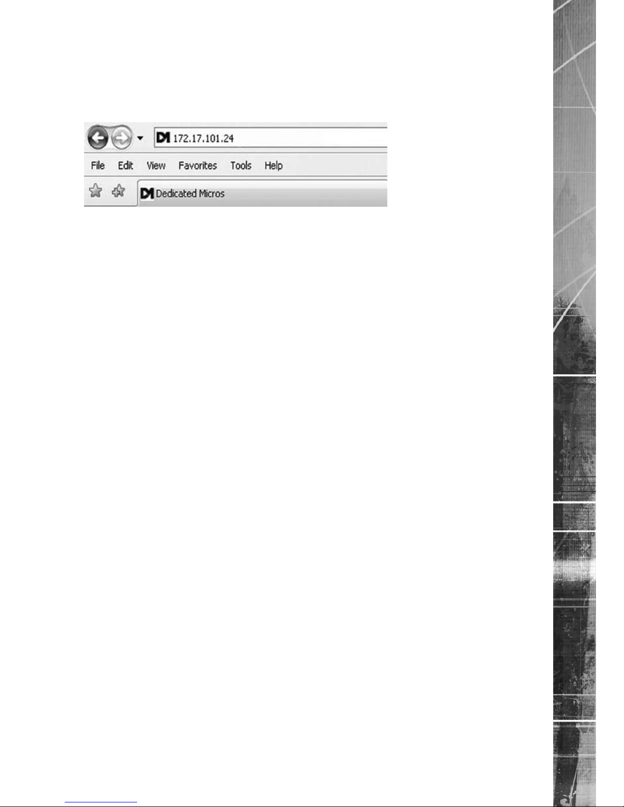
Accessing the Conguration Webpages
The unit can be congured using the webpages. To access these:
1. Launch Internet Explorer (or similar web browser package).
2. Type the URL for the unit (IP or DNS address).
3. The Opening menu page will be displayed.
6.13
Page 20

Dedicated Micros ©2009
20
SD Advanced
Remote Control
The IR Remote Control offers all the control functionality required to navigate the menus.
Note: Not all buttons on the IR Remote Control are relevant for the Unit.
Key Button
Switches the Remote Control to ‘TV’
mode and sends codes understood by
common TV sets.
Switches the Remote Control to ‘DVR’
mode. Note the DVR mode is the
default mode of operation.
Toggle the speed of PTZ camera
movement (two speeds available).
Use the Zoom button to zoom in/out
with a selected camera. Also used to
zoom (x2) into Live or Playback images.
This button will change the Zoom Keys
operation to focus or iris functions
(when available).
Use this button to cycle through
available cameras.
This button should be pressed (followed
by a numeric entry) to carry out auxiliary
actions on a PTZ camera.
Press the Menu button to enter the
Conguration menus.
Press the Exit button to exit the
Conguration menus.
Page 21

Dedicated Micros ©2009
21
SD Advanced
Use the Directional and OK buttons to navigate through the
menu screens and accept changes. Also use for PTZ telemetry control
of cameras.
Use the Softkeys (Red, Green, Yellow, Purple) to directly access the
corresponding function displayed on the menu screen.
The Number pad should be used to select specic cameras and preset
positions when available.
Use the Playback buttons to interrogate recorded images. Use the LIVE
button to switch from Playback or menus to a LIVE display.
Page 22

Dedicated Micros ©2009
22
SD Advanced
Main Menu
When rst accessing the unit, the main menu will be displayed. This menu allows access to the
Conguration menus, the Viewer menus and also several Download options.
Note: The Download options will only be available if viewing remotely via an IP connection.
Select the Conguration menu tab to access the unit’s Conguration menus. Refer to ‘Navigating the
Conguration Menus’ for further guidance.
Select the Viewer menu tab to access the unit’s Viewer function. Refer to ‘Unit Operation’ for
information on the numerous Viewer features.
Select the Download menu tab to access the various Download sub-options. Select from:
• Product Manual Select to open an electronic version of the
Installation & Operation Guide.
• ObserVer Manual Select to open an electronic version of the NetVu ObserVer
User Guide. NetVu ObserVer is a free video management
software package from Dedicated Micros that allows users to
seamlessly view distributed images from any
‘NetVu Connected’ product.
• NetVu ObserVer Select to download the NetVu ObserVer video
management software.
• Java (JRE) Select to download the Java (JRE) software (from the unit).
This software is required to successfully view Conguration
and Viewer menus remotely.
IMPORTANT: By default, no Usernames and Passwords are required to access any of the
various menus. Usernames and Passwords can however be added to regulate
access to the Conguration and Viewer menus. Refer to the ‘Console Settings->
User Accounts’ menu for information on establishing Usernames and Passwords.
Page 23

Dedicated Micros ©2009
23
SD Advanced
Navigating The Conguration Menus
When accessing the conguration menus, the menu tree will be displayed.
The conguration pages are navigated using the menu tree (displayed on the left of each page).
Selecting one of the menu options will display the relevant page. Associated sub-menus will then
be available.
Relevant menus can also be accessed directly from other menu screens via the coloured softkey
options shown at the base of each menu. The options available will depend on the menu being
viewed. Select a softkey option by pressing either the corresponding button on the IR Remote
Control (if viewing the menus locally), or by selecting the relevant option via the PC mouse (if
viewing the webpages).
Note:
Any changes made via the webpages are automatically saved when the page is closed. To
‘manually’ save changes, select the Save option.
Page 24

Dedicated Micros ©2009
24
SD Advanced
Using the IR Remote Control
Press the MENU button to access conguration menus via a connected local monitor. The menu will
have a red indicator highlighting the rst option. Select a main menu heading to open a drop down
list of further sub-options. Press the Down Directional button to highlight the next menu option, press
OK to open the highlighted menu.
Press the Right Directional button to highlight the rst editable parameter on the screen.
Use the Left/Right/Up/Down Directional buttons to move between elds.
Select OK to start editing a eld (the option will be outlined in green).
Use the Up/Down Directional buttons to change the settings within an editable eld.
Use the OK button to accept a new setting. Use the coloured softkeys to select the accompanying
colour option on screen i.e. red button to select the red option. To undo changes made to any menu,
select the Refresh (Purple) option.
Note: See below for information on entering alpha-numeric data.
Using the Front Panel Interface
The Conguration and Viewer menus can be navigated and edited using the unit’s front panel
interface (via a connected local monitor).
Navigate the menu tree via the Up/Down Directional buttons. When a menu is highlighted, open by
pressing the OK button.
Use the Left/Right/Up/Down Directional buttons to move between elds.
Select OK to start editing a eld.
Use the Up/Down Directional buttons to change the settings within an editable eld.
Use the OK button to accept a new setting.
Use the Exit button to leave the Conguration pages and open the Viewer menu.
Use the colour bar buttons (Red, Green, Yellow, Blue and Purple) to directly access the
corresponding function displayed on the menu screen i.e. red button to select the red option.
When viewing recorded images, use the Playback buttons (Play, Stop, Fast Forward and Rewind) to
navigate the images.
Use the Goto button to display the Goto menu. This menu can be used to display recorded images
from a specic date/time. Refer to Unit Operation->GoTo Menu for further information.
Use the Copy button to display the Copy menu. This menu can be used to copy recorded images to
a connected USB device or disc. Refer to Unit Operation->Copy Menu for further information.
Use the Live button to switch to display live images from a camera when viewing recorded images
from the same camera.
Use the Menu button to display the conguration menus.
Note: See below for information on entering alpha-numeric data.
Entering Alpha-Numeric Data via a Local Monitor
Numeric or text data is entered using the on-screen Virtual Keyboard (Arrow Key Editor).
To display the Virtual Keyboard, navigate to the relevant text input box using the Directional buttons
and double press the OK button twice on the IR Remote Control or Front Panel Interface. The Virtual
Keyboard is displayed.
Page 25

Dedicated Micros ©2009
25
SD Advanced
Use the Directional buttons to move between characters, use the OK button to select a character.
Select ‘Submit’ to enter details, press ‘Cancel’ to exit without entering any text.
Alpha-numeric data can also be entered in either upper or lower case format by ‘multi-tapping’
a relevant button. For example, with the cursor located in the text entry window of the Virtual
Keyboard, repeatedly tap button ‘2’ to cycle through the following characters: 2,A,a,B,b,C,c,2 etc.
To select one of these characters, simply stop tapping the button when the chosen character is
displayed. The cursor will then progress, ready for the next character entry.
Note: A USB Keyboard (not supplied) can be connected via one of the USB ports on the unit. The
USB Keyboard can then be used to enter alpha-numeric data via the local menus.
Using a USB Mouse or the Webpages
Navigate the menus by clicking the tabs displayed on the left of the menu headings (on the menu
tree). The rst option is highlighted with a red tab. Select a main menu heading to open a drop down
list of further sub-options.
Highlight an editable eld by clicking on it directly.
If viewing pages locally, enter alpha numeric data via the Arrow Key Editor (see above). If viewing
remotely, enter via the PC keyboard. If available, click on the drop down menus to select settings.
Note: A selected item in the drop down list will appear highlighted.
Navigating away from a page (clicking on a different option on the menu tree) will automatically save
any changed settings. To undo changes made to any menu, select the Refresh (Purple) option.
Using a Supported Dedicated Micros Keyboards (DM/KBC1 & DM/KBC2)
The unit can also be controlled using an optional Dedicated Micros keyboard. This is connected via
the KBD connector on the rear of the unit and provides the same control functions as the I.R Remote
Control.
Note: Refer to ‘Using the optional Keyboards (DM/KBC1 & DM/KBC2)’ for further guidance.
Page 26

Dedicated Micros ©2009
26
SD Advanced
System Settings
The menus under the System Settings heading allow the unit’s core settings to be viewed, changed
and the system software upgraded.
The System option displays details about the unit including the IP address, unit serial number, MAC
address and software version.
The Unit Status page displays information about the unit’s operating condition, shows how long the
unit has been operating and the reason for the last reset. It also shows camera status and displays
any failed cameras.
The Alarm Status page shows which contacts are open, which zones are in alarm and which relays
are operating.
The Language page allows the system language to be set. The language can also be changed for
the current session only.
The Time and Date page allows the unit time and date settings to be adjusted, including setting the
timezone.
The Serial Ports page allows each of the four serial ports to be individually congured for one of a
range of operations, including EPOS, debug, PPP and telemetry.
The Audio page shows the settings available for each of the audio channels and allows conguration
of audio quality.
The Features page allows control of the different features that are available within the software
including Email reporting, webcam support and control of the display resolution.
The Maintain page allows the current conguration to be saved, and for previously saved settings to
be loaded. It also enables easy upgrade of the system software.
The PowerScript Mgmt page allows installed PowerScripts to be activated/deactivated on start-up.
Page 27

Dedicated Micros ©2009
27
SD Advanced
System
6.13
This menu shows the general information about the unit including the version of software installed,
the unit’s serial number and the allocated DHCP IP address.
Product Descriptor Details the product model.
Serial Number Identies the serial number of the specic unit.
PCB Serial Number Displays the PCB (Printed Circuit Board) serial number of the unit.
Product Code Displays a code identifying the unit’s specication.
Earliest Recording Displays the date/time of the earliest recording held on the unit.
System Name This eld can be edited to allocate a name to the unit. This is
displayed when the unit is accessed via NetVu ObserVer and is
sent when transmitting information to a Remote Video Response
Centres (RVRC).
Number of Cameras Shows the number of camera channels on the unit.
Global PPS Details the Global PPS (Pictures Per Second) recording rate for
all cameras.
Video Storage Gbytes Highlights the available video storage capacity in Gigabytes.
Video Standard Displays the video standard adopted by the unit i.e. PAL, NTSC.
MAC Address This is the MAC address assigned to the unit.
IP Address
This is the IP address allocated to the unit.
Page 28

Dedicated Micros ©2009
28
SD Advanced
Sub Net This is the subnet of the network where the unit is located.
Gateway
This is the IP address of the default gateway (router) assigned by
the DHCP server.
Software (Red) Select this option to display installed software information
(see below).
Software Menu
Software Revision This identies the version of software the unit is running.
Codec Revision This identies the codec version the unit is running.
Webpage Revision This identies the webpage version the unit is running.
Framestore Revision This identies the Framestore Revision the unit is running.
PC Apps Revision This identies the revision archive of the Viewer amd associated
PC Apps software.
Boot Software Rev. Displays the infrastructure componentry software revision.
Telem PIC Rev. This identies the version of the Telemetry control device installed
on the unit.
Page 29

Dedicated Micros ©2009
29
SD Advanced
Unit Status
This menu details information regarding the status of the unit, notably the total time the unit has
been operating and the time since its last reset. Status log information can also be exported via the
‘Export Logs’ option to either a CD/DVD or a USB device.
Time since last reset Details the time since the unit was last reset.
Total running time Details the total time the unit has been operational.
Reset code The last reset code used is displayed.
Restart reason The reason for the last restart is displayed i.e. Controlled
User Reset.
Export Log (Blue) Select this option to export log data to an inserted CD/DVD or a
connected USB device.
Total Codecs Details the current number of installed codecs.
Codecs Installed codecs currently operating as a codec will be highlighted
light green. Hover the cursor over individual buttons to display
either ‘On’ or ‘Off’. ‘On’ signies that the codec is active as
a codec.
Framestores Installed codecs currently operating as a framestore will be
highlighted light green. Hover the cursor over individual buttons to
display either ‘On’ or ‘Off’. ‘On’ signies that the codec is active as
a framestore.
Note: The ‘On’/‘Off’ text will only be displayed if viewing the Unit Status menu remotely over an IP
connection.
Page 30

Dedicated Micros ©2009
30
SD Advanced
Cameras Connected Those camera channels with cameras connected will be
highlighted light green. Those not in use will appear dark green.
Failed Cameras Those camera channels where the connection is deemed to have
failed will be highlighted light green. Those working correctly will
appear dark green.
Page 31

Dedicated Micros ©2009
31
SD Advanced
Alarm Status
This menu details information regarding the status of the unit’s alarm contacts, alarm zones and
relay outputs.
Alarm Contacts/Zones/Relay Outputs Alarm Contacts, Alarm Zones and Relay Outputs that are
in an ‘active’ state are shown light green. ‘In-active’ ones
appear dark green (not illuminated).
Page 32
Dedicated Micros ©2009
32
SD Advanced
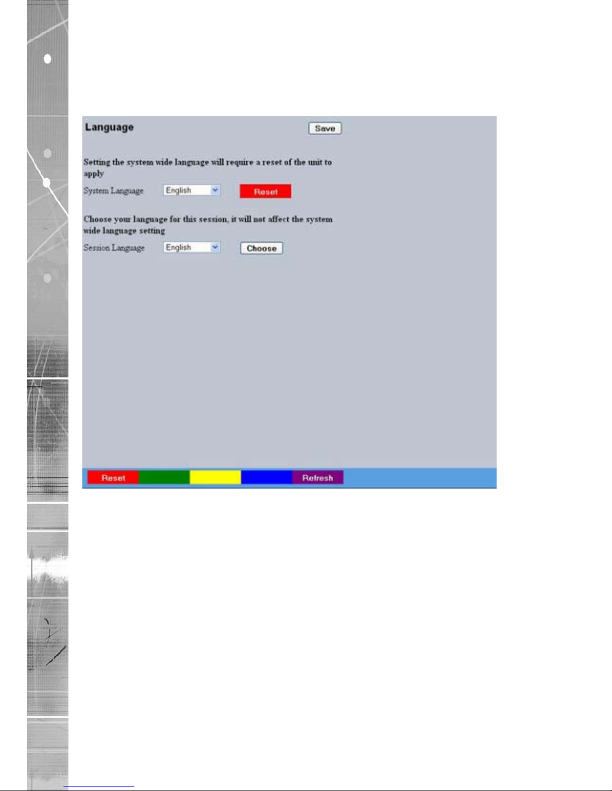
Language
This menu allows the system language to be set. Changing the System Language will effect all
menu pages. If required, the language can also be changed for the current session only.
System Language Select to change the system language setting.
Reset (Red) Select to reset the unit.
Note: The unit MUST be reset to implement system language changes. Refer to
System Settings->Maintain for guidance on resetting the unit.
Session Language Select to change the language settings for the current
session only.
Choose Select to immediately activate session language changes.
Page 33

Dedicated Micros ©2009
33
SD Advanced
Time and Date
This menu allows the time and date to be set on the unit. Required timezone information can also be
established and the unit time synchronised to that of the PC being used to view the webpages.
System Time The current system time and date is displayed.
Current Time Zone Displays the currently selected time zone settings.
Time Format As default, the time displayed is in 12 hour format. This can be
changed to 24 hour if required.
Date Format
As default, the date is entered dd/mm/yy. It can also be displayed
as mm/dd/yy or yy/mm/dd.
Set Time Enter a current time for the unit.
Set Date Enter a current date for the unit.
Set Time (Green) When current time/date as been entered, select this button to
implement changes.
Time Zone Select the relevant timezone offset from the accompanying drop
down menu.
SNTP Server A Simple Network Time Protocol (SNTP) server allows external
devices to connect and set their current date and time settings to
that of the SNTP. If required, enter the SNTP server IP
address here.
Page 34

Dedicated Micros ©2009
34
SD Advanced
PC Time Displays the system time of the PC currently being used to view
the webpages.
Sync Time (Blue)
Use this button to synchronise the time of the unit to that of the
PC being used to view the webpages.
Note: The PC Time and Sync Time options will only be available if viewing the menu via
the webpages.
Page 35
Dedicated Micros ©2009
35
SD Advanced
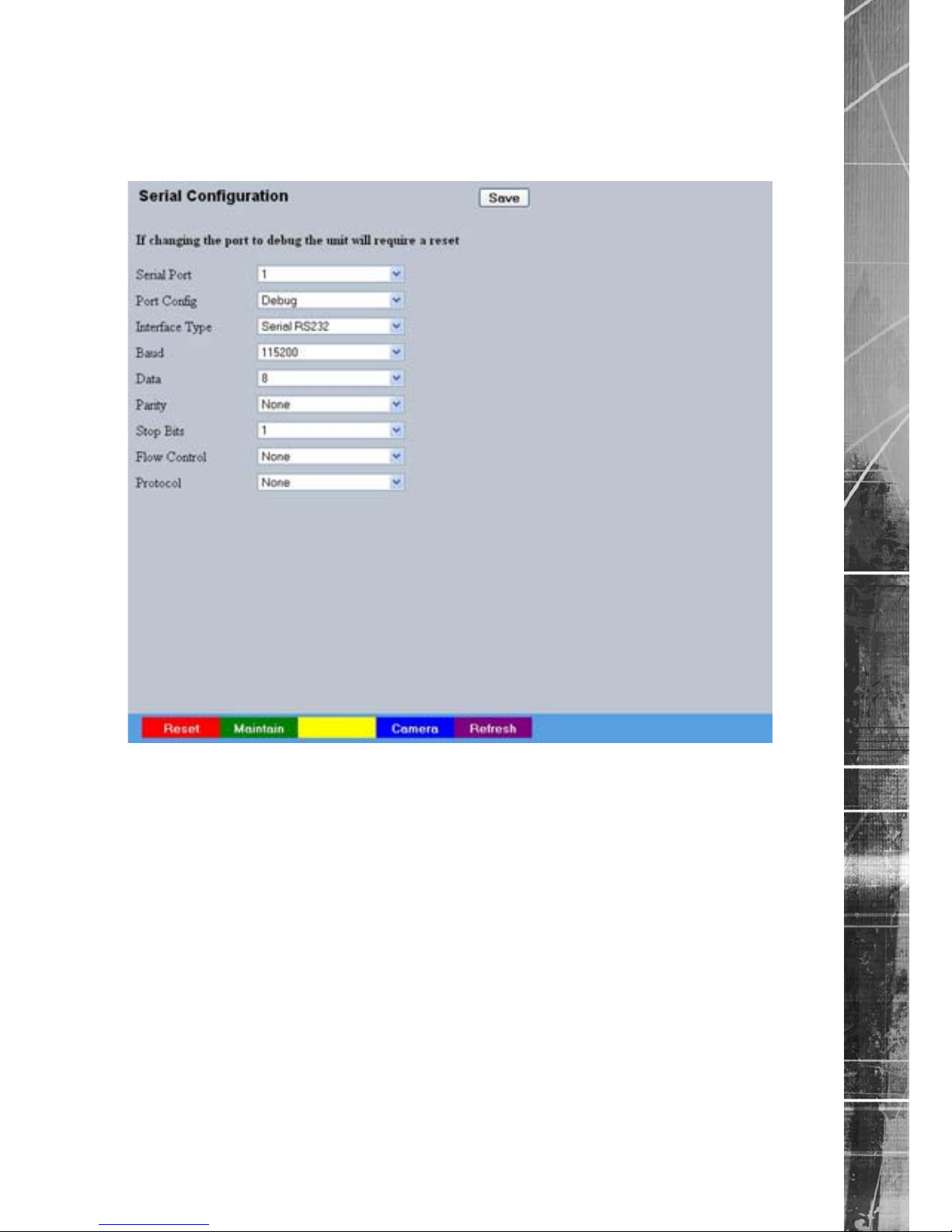
Serial Ports
This menu allows conguration of the unit’s Serial ports. Refer to ‘Installing the Unit’ for
installation information.
Serial Port These are the four serial ports available.
Port Cong The serial ports can be congured to specic uses.
Select from:
None Switches port off
Debug Sets port for serial communications
PPP Sets port for Point to Point Protocol
Telem Sets port for Telemetry purposes
Comm Sets port for Comms purposes
EPOS Sets the serial port for connection to an
EPOS (Electronic Point Of Sale) device
Interface Type Choose the type of serial interface being used. Select from
RS232, RS485 or RS422.
Baud/Parity/Data/Stop/Flow Control
These options allow the Serial port communication settings to
be congured.
Note:
When a telemetry protocol is selected, these settings will default to pre-determined values
and should not normally be altered.
Protocol This is a drop down list of serial telemetry protocols supported by
the unit.
Note: Refer to ‘Appendix E’ for a full list of supported telemetry protocols.
Page 36
Dedicated Micros ©2009
36
SD Advanced
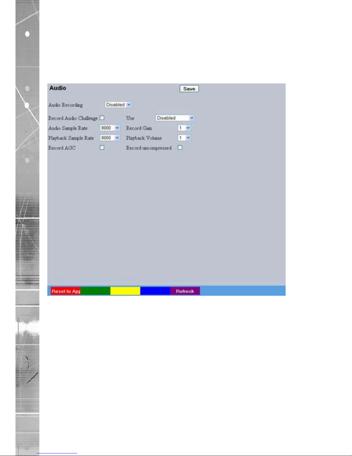
Audio
The Audio menu allows settings for the bi-directional audio channels to be edited. Audio can be
recorded from camera inputs via input 2. Challenge audio i.e.originating from an Operator using
NetVu ObserVer at a Remote Video Receiving Centre (RVRC) can be recorded via input 1. This
combined audio is then available on Audio Output 1. Refer to ‘Installing the SD Advanced for audio
hardware installation information.
Audio Recording Select ‘Enable’ to activate Audio recording.
Record Audio Challenge Select this option to record an audio challenge originating from an
operator at an RVRC.
Use Select the intended use of the incoming audio i.e. ‘Local
Playback’, or ‘Challenge’. Select ‘Disabled’ to deactivate.
Audio Sample Rate Audio can be recorded at 8Hz, 11Hz, 16Hz or 22Hz.
Record Gain This option allows the Record Gain level to be set. This is the
base setting from which the AGC (Automatic Gain Control) will
operate. Select from 1 to 15. The default and recommended
setting is 15.
Playback Sample Rate Audio can be played back at 8Hz, 11Hz, 16Hz or 22Hz.
Playback Volume Select a volume setting between 1 to 64 for audio playback.
Record AGC Select this option to activate the AGC function. AGC helps
produce a better quality recording by removing background
noise/distortion.
Record uncompressed Select this option to record audio in an uncompressed format.
Note: Recording in uncompressed format will signicantly increase the disk space used.
Page 37
Dedicated Micros ©2009
37
SD Advanced
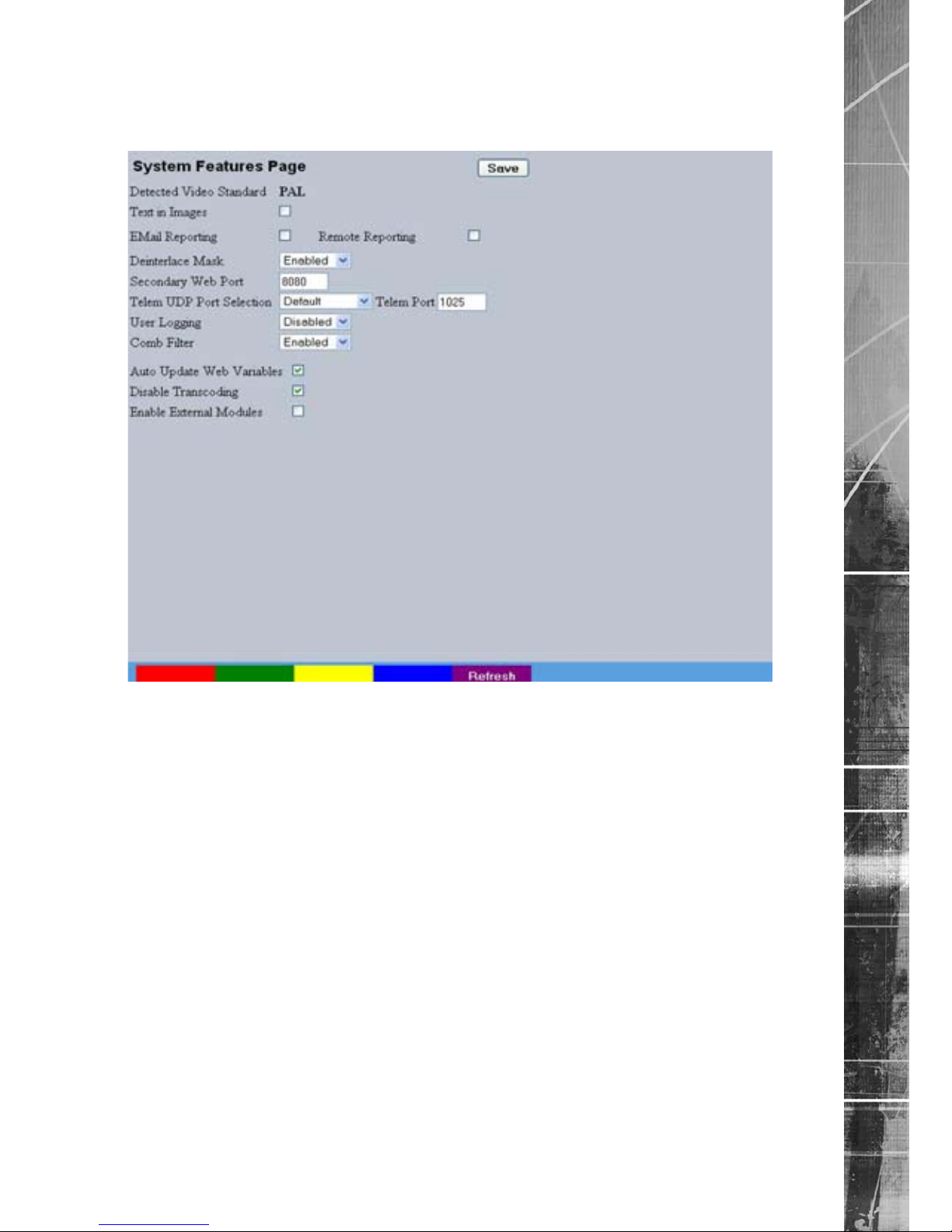
Features
This menu enables the activation of system features such as Email Reporting.
Detected Video Standard The unit automatically detects the video standard being used i.e.
PAL/NTSC.
Text in Images Select this option to activate the Text in Images function, refer to
‘Text-Text In Image’ for more information.
Note: When de-selected here, the ‘Text in Image’ menu will no longer be displayed in
the menu tree.
Email Reporting Select this option to activate the Email Reporting function, refer to
‘Network Settings->E-mail’ for more information.
Note: When de-selected here, the ‘Email Reporting’ menu will no longer be displayed in
the menu tree.
Remote Reporting Select this option to activate the Remote Reporting function, refer
to ‘Network Settings-Remote Reporting’ for more information.
Note: When de-selected here, the ‘Remote Reporting’ menu will no longer be displayed in
the menu tree.
Deinterlace mask Select this option to improve display clarity and minimise the
comb effect that may be visible when recording high motion
scenes in 4CIF mode.
Secondary Web Port If the default port setting for web serving has already been
allocated, it is possible to congure a second port number
i.e. the secondary web port can be set to 8000 if the default web
port (80) is blocked by the network or rewall.
Page 38

Dedicated Micros ©2009
38
SD Advanced
Telem UDP Port Selection Select ‘Automatic’ to enable the unit to select a suitable port for
telemetry purposes.
Select ‘Default’ to use the default port settings (1025).
Select ‘User Dened’ to use settings entered in the ‘Telemetry
Port’ option.
Telemetry Port Enter the port settings for telemetry data here. The default setting
is 1025.
User Logging Enable this option to activate User Logging. Refer to ‘Appendix C’
for further information regarding the User Logging function.
Comb Filter Enable this option to activate the Comb Filter function. Comb
Filter can help improve the ne details of a video signal image by
ltering the luminance and chrominance separation process.
Auto Update Web Variables Congures the unit to update all system variables required for an
automatic upgrade without requiring conrmation. Do not check
this box if you run a customised applet.
Disable Transcoding Select to disable the unit’s transcoding capabilities. In normal
circumstances this should always remain enabled, however it can
be useful to disable the feature when conducting maintenance.
Enable External Modules Select to enable any connected RS485 alarm modules.
Page 39
Dedicated Micros ©2009
39
SD Advanced
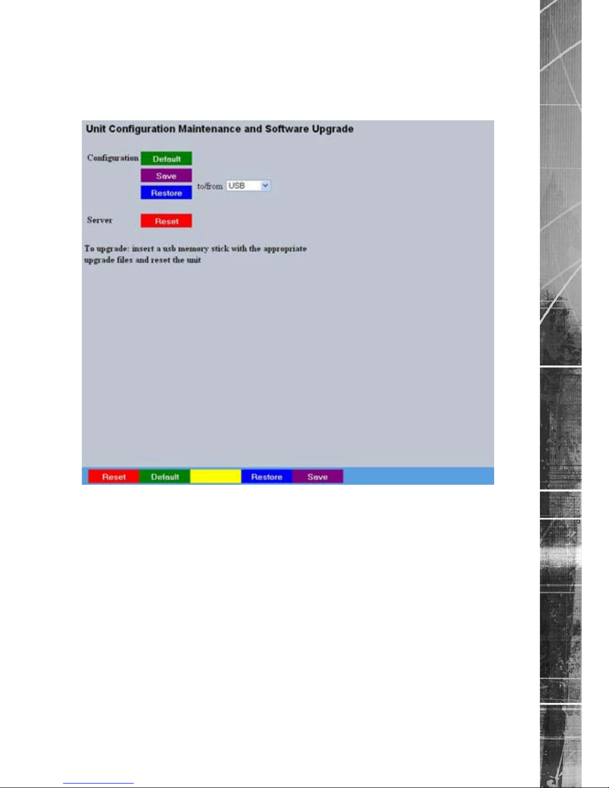
Maintain
This menu allows the unit to be reset and a software upgrade to be performed via an inserted
CD/DVD or a connected USB device. Current unit settings can also be saved for future use and
previously saved settings restored.
Conguration
Default (Green) Select to return the unit to its factory default settings.
Note: Selecting the Default button will cause the system to reboot.
Save (Purple) Select to save current unit settings to the selected media.
Restore (Blue) Select to restore previously saved settings from the
selected media.
Note: Selecting the Restore button will cause the system to reboot.
To/From Select the relevant media device to save to or restore from i.e.
USB or CD/DVD.
Server
Reset (Red) Select to cycle the power to the unit.
IMPORTANT: To upgrade the unit, insert a media device containing relevant software upgrades
and select ‘Reset‘.
Note: For the latest software upgrades, please refer to the Dedicated Micros
website: www.dedicatedmicros.com
Page 40
Dedicated Micros ©2009
40
SD Advanced
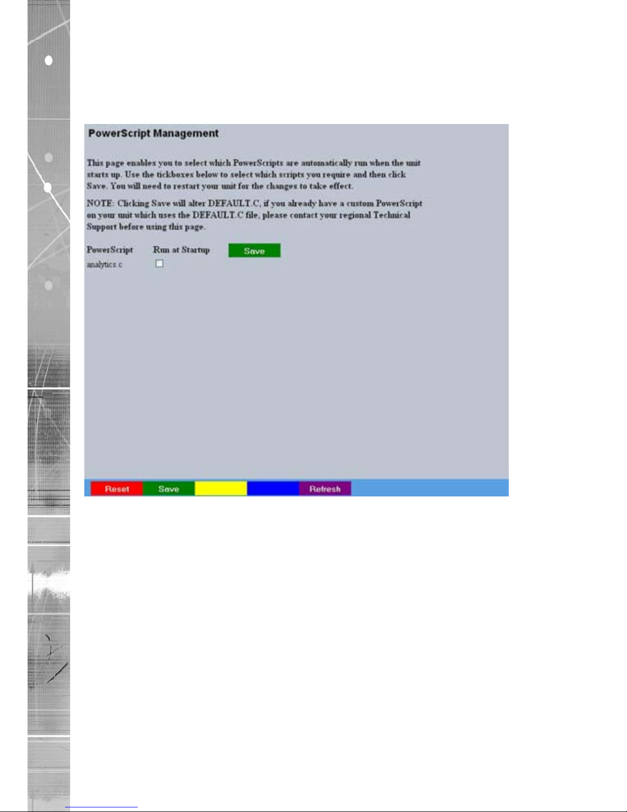
PowerScript Mgmt
This menu enables installed PowerScripts to be activated/deactivated on start-up. Use the
tickbox(es) to select/deselect installed PowerScripts, then select Save (Green). A system reset will
be required for the changes to take affect.
Note: Changes this page will alter the ‘Default.C’ le. If you already have a custom PowerScript
on your unit which uses Default.C, please contact Dedicated Micros Technical Support for
guidance Tel: +44 (0) 845 600 9502 for further guidance.
Page 41

Dedicated Micros ©2009
41
SD Advanced
Display Settings
The menus under the Display Settings heading allow the unit’s Viewer display settings to be altered
and User Account details to be viewed and changed.
The Viewer Defaults page allows the Viewer menu settings to be congured.
The Display page controls how the local monitors present information. They control whether text
will be displayed on the Main or Spot monitors, the colour of that text, and how long cameras being
displayed in sequence will be shown on screen.
The Map Cong page allows images to be imported and used as maps displayed in the Viewer
menus. Hot spots can be added to allow quick navigation to individual cameras.
The Map Data page allows Map Cong information to be saved for future use. Previously saved
data can also be uploaded.
The User Accounts page helps protect conguration procedures by limiting access to specic users
via accounts and passwords.
Page 42

Dedicated Micros ©2009
42
SD Advanced
Viewer Defaults
This menu allows conguration of settings for the Viewer function. Refer to ‘Operating The Viewer’
for more information regarding this feature.
Default settings can be congured for accessing the Viewer function via a local monitor and also for
accessing remotely via a network connection.
Default Image Format Images from connected cameras can be displayed in either JPEG
or MPEG format.
Default Image Req Images displayed full screen in the Viewer menus can be shown
in either High Medium or Low resolution.
Default Multi Req Images displayed in multiscreen in the Viewer menus can be
displayed in either High Medium or Low resolution.
Default Multi Display This controls how the unit will display the multiscreen option when
selected via the Viewer menus. The default setting is 16 way.
Select from: Full
Quad
6 way (6 cameras displayed per monitor)
7 way (7 cameras displayed per monitor)
9 way (9 cameras displayed per monitor)
10 way (10 cameras displayed per monitor)
13 way (13 cameras displayed per monitor)
16 way (16 cameras displayed per monitor)
PinP (Picture in Picture)
Page 43

Dedicated Micros ©2009
43
SD Advanced
Video Output mode Select the display output that best suits the viewing monitor.
Select from:
PAL Default
PAL Reduced
VGA 800x600
VGA 1024x768
Note: It will be necessary to reboot the unit to implement any change to the Video Output Mode.
Applet Location The location of the unit’s Viewer menu applet is displayed. The
default location will always be the applet installed on the unit.
If accessing multiple units via a remote connection, all can be
assigned the same Viewer applet. This will lessen the load time
required when accessing different DVRs/Servers.
For example, if a local unit and a remote DVR are to be accessed, it
is possible to set the Applet location for both DVRs as the local unit.
If viewing the unit remotely, Dedicated Micros provide a remote applet
located on the Dedicated Micros website (www.dedicatedmicros.
com/software_release/index_rmware.php). Due to possible bandwith
restrictions on the network the DVR is located, using this remote
applet may improve data transfer speeds.
Page 44

Dedicated Micros ©2009
44
SD Advanced
Display
This menu allows conguration of monitor settings used when viewing camera images and text data.
Main monitor text It is possible to select text to be displayed on the main monitor.
The text displayed will include; time, date, mode of operation (Set,
Unset or Override), camera number and camera title.
Text Colour The colour of the displayed text can be changed. Select from the
options available in the drop down list.
Background Colour A black background appears by default around the text. It is
possible to change the colour of this background. Select from the
options available in the drop down list.
Sequence Dwell (secs) The sequence dwell time can be set from 1 to 99 seconds. The
dwell time is the period a camera’s images are displayed before
switching to the next camera in the sequence.
Spot monitor text It is possible to select text to be displayed on the spot monitor.
The text displayed will include; time, date, camera number and
camera title.
Spot Sequence Dwell The spot sequence dwell time can be set from 1 to 99 seconds.
The dwell time is the period a camera’s images are displayed on
a connected spot monitor before switching to the next camera in
the sequence.
Spot Sequence Setup All of the unit’s camera input channels are shown. To include any
of these camera channels in the spot monitor sequence, selected
the accompanying tickbox.
Page 45

Dedicated Micros ©2009
45
SD Advanced
Map Cong
This menu allows images to be imported and used as maps that can be displayed in the Viewer
Menus. The map can then have hotspots added to allow quick navigation to individual cameras.
An overview ‘System Selection Map’ can also be added to navigate between different systems.
Congure Map Leave as ‘Local System Map’. This is the map from which
connected cameras can be accessed.
Graphic Location Enter the location of the relevant map graphic, including the full
I.P address of the server holding the map. The map image will be
displayed if linking is successful. The linked map can be in gif or
jpeg format and should not exceed 500 by 350 pixels.
Map Screen Offset These coordinates represent the top left corner of the map graphic
as displayed in the Viewer menu.
Camera Select Select which camera is to be linked to the created hotspot.
Activate Hotspot Select to activate and display the camera hotspot.
Hotspot Radius Enter the radius (in pixels) of the hotspot.
Increment by If using the Decrement (Red) or Increment (Green) buttons, enter
the size (in pixels) that the hotspot will increase/decrease.
Decrement (Red) Select to reduce size of hotspot.
Increment (Green) Select to increase size of hotspot.
Page 46

Dedicated Micros ©2009
46
SD Advanced
Hotspot X coord Use to position the centre of the hotspot along the X axis e.g.
entering 20 would place the hotspot centre 20 pixels from the left
edge of the map.
Hotspot Y coord Use to position the centre of the hotspot along the Y axis e.g.
entering 20 would place the hotspot centre 20 pixels from the
bottom edge of the map.
Note:
The hotspot can also be positioned by clicking directly on the map.
Hotspot Origin (deg) This option should be used when the hotspot relates to a
Dedicated Micros Oracle Dome camera. Clicking the hotspot will
send the Oracle Dome camera to a pre-determined view (absolute
positioning). However if the dead centre of the hotspot is selected,
the camera will be viewed from its current location.
The absolute positioning point will depend on the data entered
here. A setting of ‘0’ would result in the camera facing its Original
(base) position. To change the preset position, enter a number
between 1 and 360. A setting of 20 would set the preset position
to 20 degrees to the right of its ‘origin’ position, 180 would send it
to face in the opposite direction (of its base position) . Refer to the
‘Viewer Menus-Program menu‘ for information on establishing an
Origin position for a PTZ camera.
Page 47

Dedicated Micros ©2009
47
SD Advanced
Map Data
The Map Data menu allows Map Cong data to be Imported/Exported. This enables map data to be
saved and stored for future use, or used between multiple units.
Note:
The Map Data menu will only be available when viewing the menu pages remotely i.e. via
the webpages.
To save map data, highlight and copy all text displayed in the Map Data text window, then save this
data as a text le.
To import data, copy relevant text from an external location and paste into the Map Data text
window. When the menu is exited, this data will be used as the Map Cong settings.
Note:
If importing data, remember to rst save any current map data as required.
Page 48
Dedicated Micros ©2009
48
SD Advanced
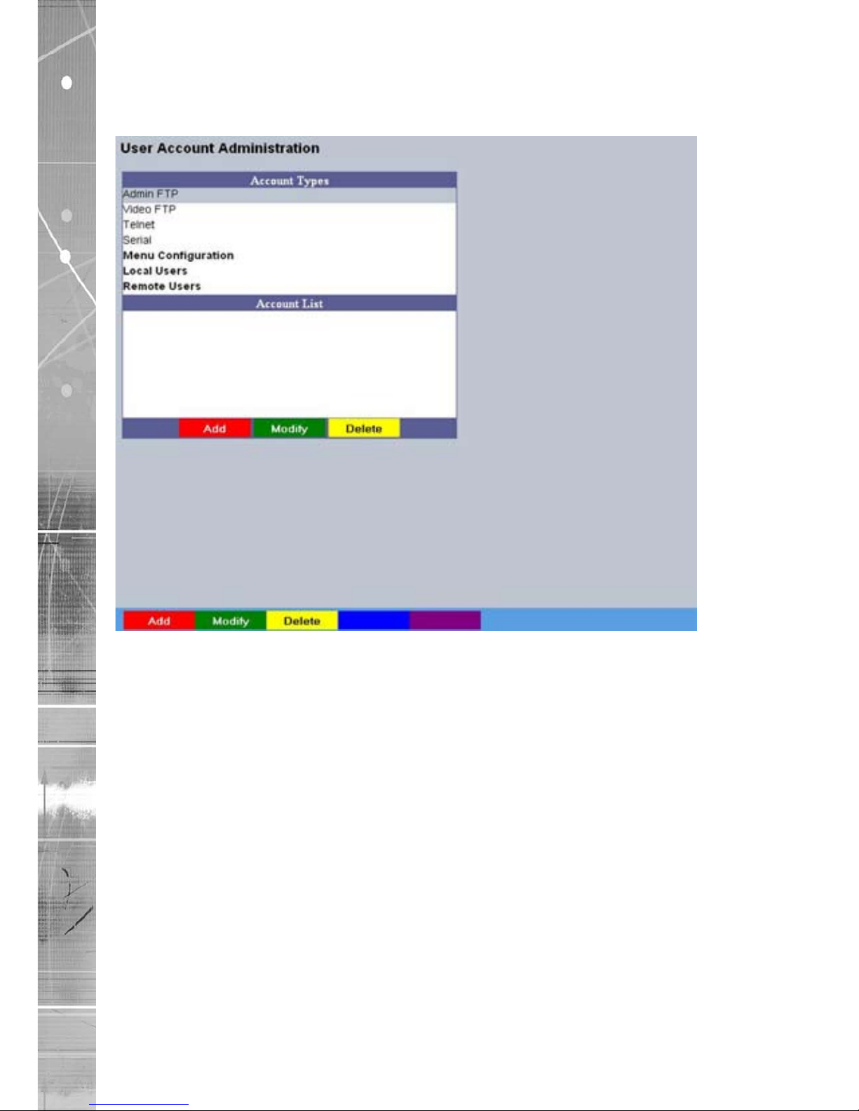
User Accounts
The unit can protect conguration procedures by limiting access via usernames and passwords.
Account Types The available account types for which users and passwords can
be assigned privileges are:
• Admin FTP
Assigning username and password requirements
for the Admin FTP function will limit access to the
unit via an FTP connection.
• Video FTP
Assigning username and password requirements
for the Video FTP function will limit access to
the Video FTP archiving feature (used with DM’s
NetVu ObserVer).
. • Telnet
Assigning username and password requirements
for Telnet connections will limit Telnet
access to the unit (Telnet can be used to upgrade
the unit).
• Serial
Assigning username and password requirements
for Serial connections will limit access via a
Serial link.
Page 49

Dedicated Micros ©2009
49
SD Advanced
• WebPage Conguration
Assigning WebPage Conguration privileges will
limit access to the Conguration menus when
viewed remotely. When implemented,
the user will be prompted for a username and
password before access to the Conguration
menus (via the main menu) will be granted.
• Menu Conguration
Assigning Menu Conguration access
privileges will limit access to the
Conguration menus when viewed locally.
When implemented, the user will be prompted for
a username and password before access to the
Conguration menus (via the main menu) will
be granted.
• Local Users
Assigning Local Users access privileges
will limit access to the Viewer pages for local
users. When implemented, the local user will be
prompted for a username and password before
access to the Viewer pages (via the main menu)
will be granted.
• Remote Users
Assigning Remote Users access privileges
will limit access to the Viewer pages for remote
users. When implemented, the remote user will be
prompted for a username and password before
access to the Viewer pages (via the main menu)
will be granted.
When granting access privileges to Local and Remote Users, it is possible to limit access to specic
cameras. Via the Camera Selection segment of the Add New Account menu, enter those cameras
for which access will be permitted. Select the cameras in accordance with the input channel they’re
connected to on the rear of the unit. For example, if wanting to allow access to camera 1 to 3
inclusive, enter: 1-3. If wanting to grant access to cameras 1,3 and 6, enter 1,3,6. If no camera data
is entered, access will be allowed to all connected cameras in both live and playback modes.
Note: There are no default usernames and passwords for any of the Account Types. If none are
assigned, access will be granted to all users and no request for a username and password
will be made.
Account List When an Account Type is highlighted, details of users with access
will be displayed.
Add Highlight an administration feature i.e. Serial and select ‘Add’.
Enter the new User Name and Password. That user’s name will
now be displayed in the account list.
Modify/Delete To modify or delete a user’s settings, highlight the user in the list
and press the relevant button to Modify or Delete.
Note: If viewing the User Accounts page via a local monitor and navigating with the I.R Remote
Control. Press the right directional button from the menu tree to access the Account List.
Page 50

Dedicated Micros ©2009
50
SD Advanced
Camera Settings
The Camera Settings menus allow conguration of cameras connected to the unit. Refer to the
individual menus for further details.
The Camera page allows the quick conguration of all connected local camera channels.
The I.P Camera page allows conguration of incoming digital video streams originating from an
IP address.
The Camera Setup page allows the colour and contrast settings for each individual camera to be
adjusted (with a dynamic preview available).
The Camera Telemetry page enables telemetry capable cameras to be congured.
Page 51
Dedicated Micros ©2009
51
SD Advanced
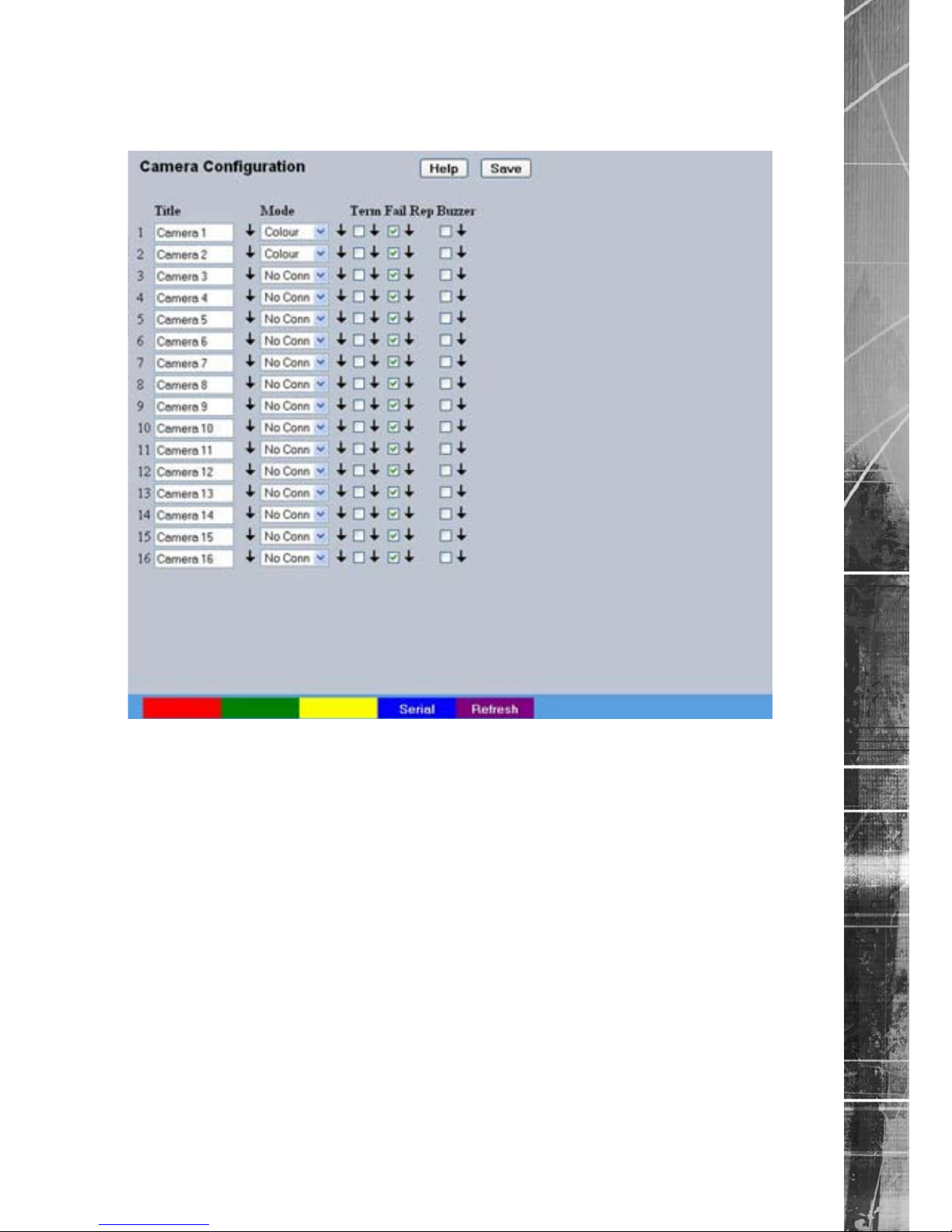
Camera
This menu allows the conguration of active local camera channels.
Title Each of the camera titles can be edited for ease of use i.e. the
camera type, location or view description could be used.
Note: If a camera title is entered via the local monitor, an on-screen virtual keyboard will be
displayed to aid text entry.
Mode The settings will default to ‘Colour’. If Monochrome cameras
are used, select ‘Mono’. Selecting ‘Mono’ will remove colour
patterning. If a particular channel is not in use or the camera has
failed, select ‘Not Connected’.
Term The unit will automatically terminate the camera input with 75Ω.
This should be disabled if the video feed is looped through to
another device.
Fail Rep Select this option to activate a Failure report in the event of
camera connection failure.
Note: The arrow button displayed next to each textbox allows settings to be replicated for those
cameras listed below. This will only affect the adjacent option i.e. Mode arrow will replicate
the Mode setting to cameras below the clicked arrow.
Page 52
Dedicated Micros ©2009
52
SD Advanced
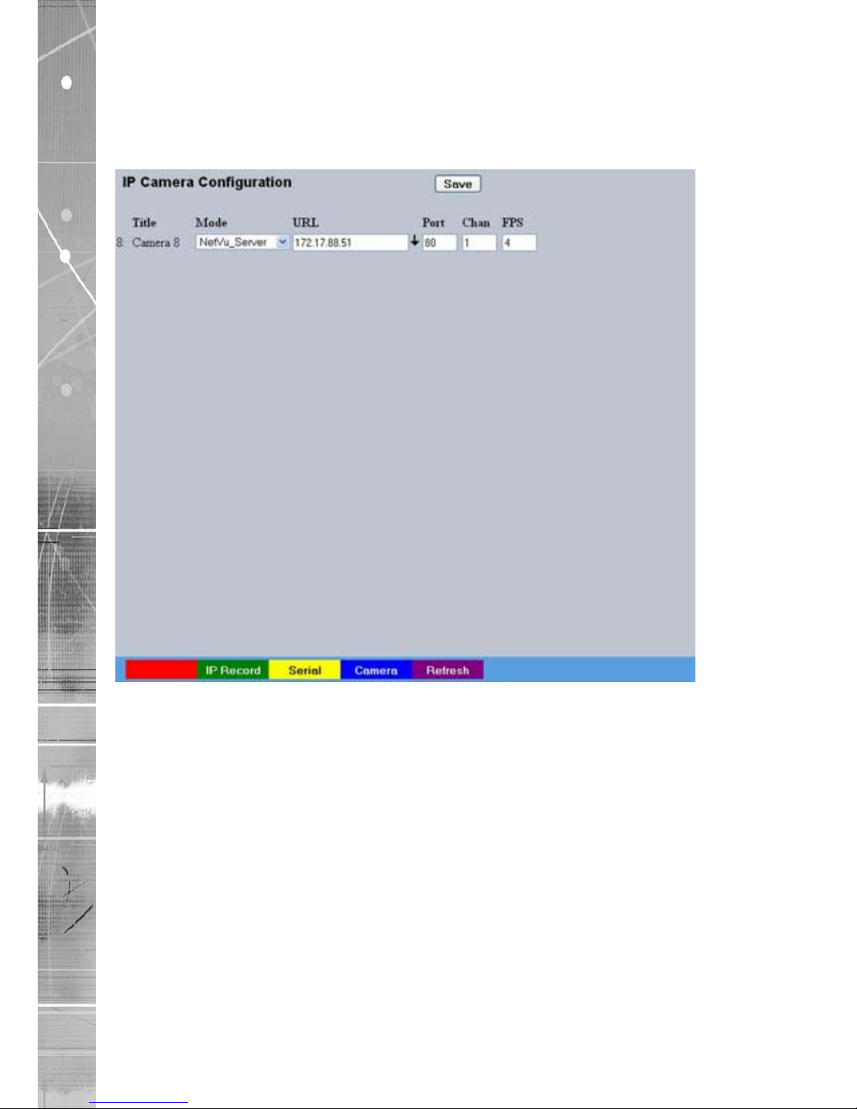
IP Camera
This menu allows the conguration of connected IP Cameras (cameras connected directly to a
network broadcasting a digital video stream from an IP address). It can also connect to other NetVu
Connected DVRs and treat one of the network feeds from that DVR as a digital video stream.
Title Displays the camera title.
Mode Select the type of IP camera i.e. if the stream is originating
from a NetVu Connected server select ‘NetVu Server’. If from
a NetVu camera such as a Dedicated Micros CamVu 2000,
select ‘NetVu Camera’.
URL Edit the URL address of the IP camera source.
Port If required edit the port input data. This will default to 80 (HTTP).
Chan If required edit the channel input data.
FPS Edit the FPS (Frames per Second) recording settings.
Page 53
Dedicated Micros ©2009
53
SD Advanced
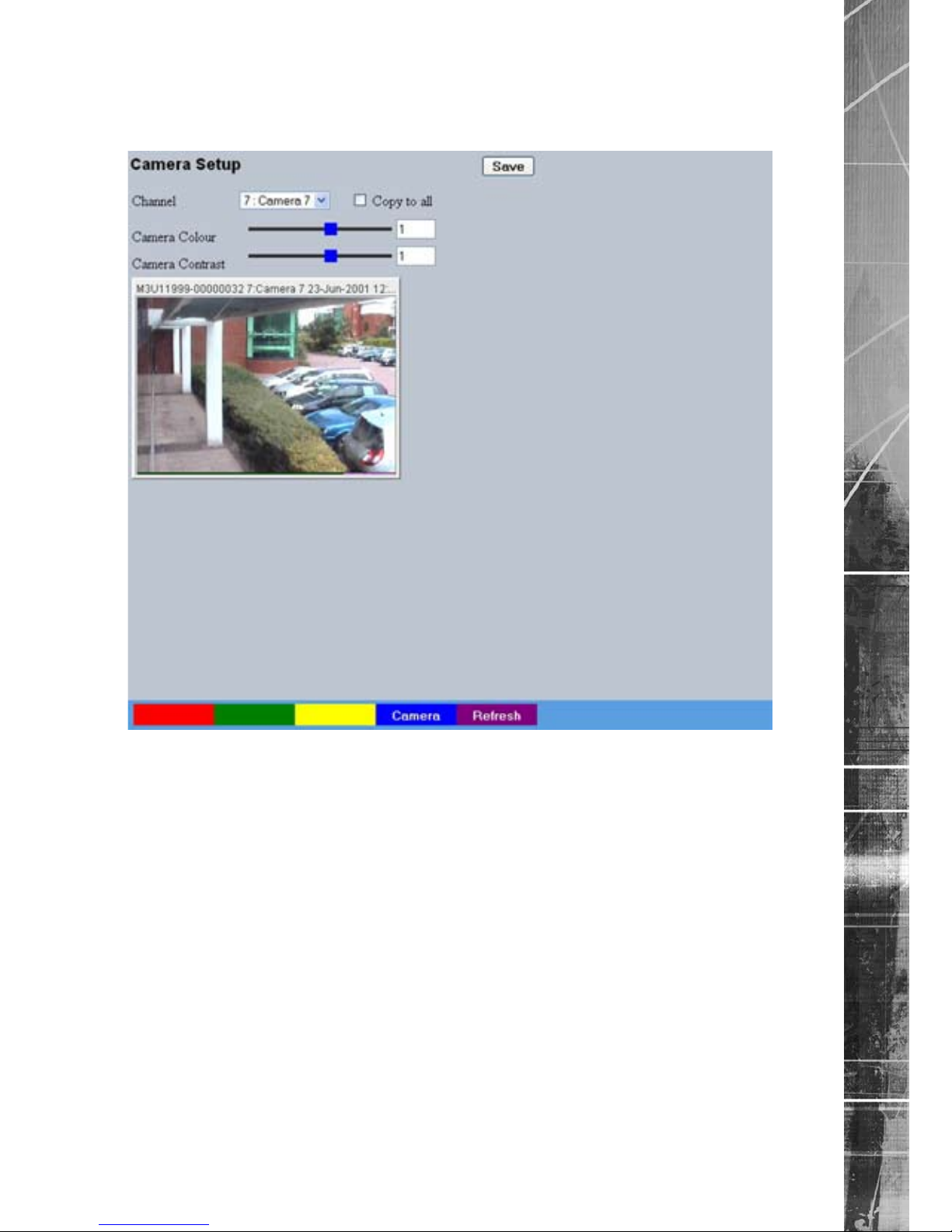
Camera Setup
This menu allows the colour and contrast settings for each individual camera to be adjusted.
Channel Select a camera channel for review and adjustment.
Copy to all Select this option to apply current settings to all
connected cameras.
Camera Colour Select a colour value from -8 to +8 via the slidebar or enter a
number directly into the accompanying textbox.
Camera Contrast Select a contrast value from -8 to +8 via the slidebar or enter a
number directly into the accompanying textbox.
Page 54
Dedicated Micros ©2009
54
SD Advanced
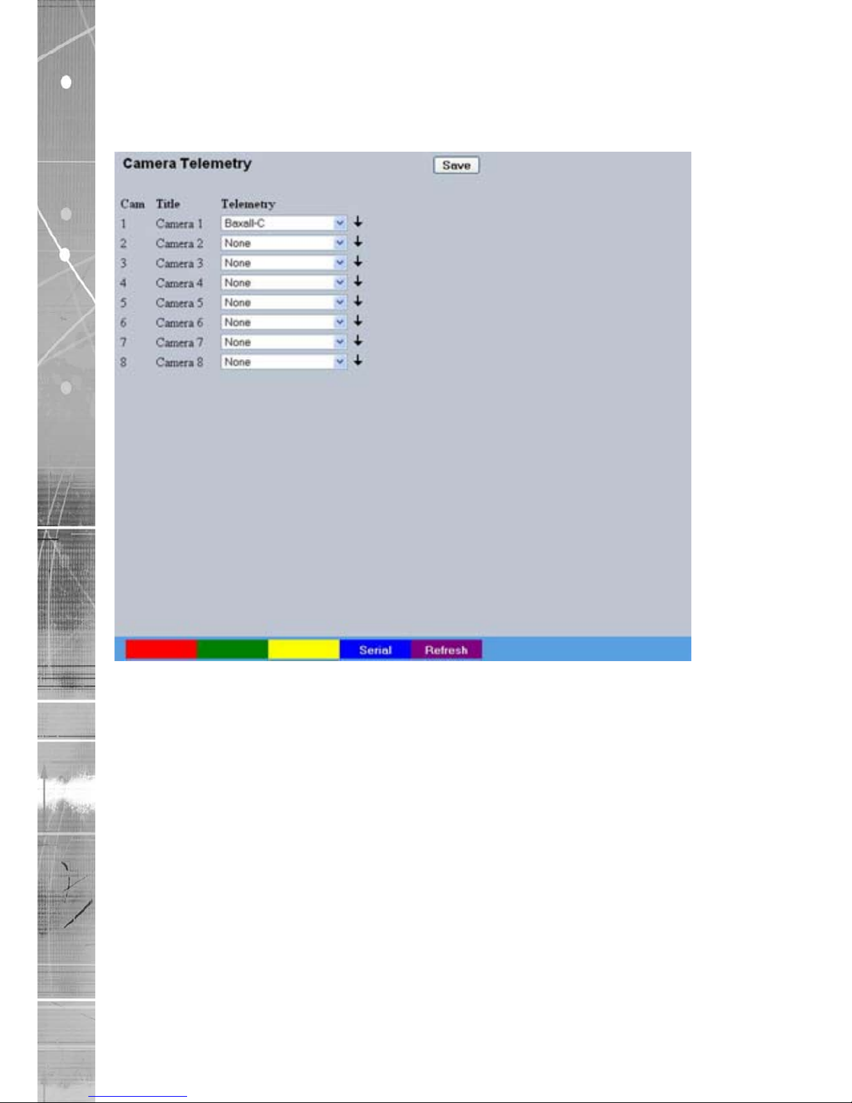
Camera Telemetry
This menu allows conguration of telemetry capable cameras and the assignment of
telemetry protocols.
Cam Lists available camera channels.
Title
Titles assigned to each camera are displayed.
Telemetry
If a telemetry capable camera is connected, the appropriate
control protocol should be selected from the accompanying drop
down list. Refer to ‘Appendix E’ for details of supported
telemetry protocols.
Note: The arrow button displayed next to each textbox allows settings to be replicated for those
cameras listed below. This will only affect the adjacent option i.e. Telemetry arrow will
replicate the Telemetry setting for cameras below the clicked arrow.
Page 55

Dedicated Micros ©2009
55
SD Advanced
Record Settings
The Record Settings menus allow conguration of the unit’s record functions. Record settings can
be congured for normal operation, on alarm, by schedule and for set holiday and weekend periods.
Selected video data can be saved and protected. Refer to the individual menus for further details.
The Record page allows the basic Recording settings to be edited.
The Prole Record page
allows the recording conguration to be based on specic priorities. The record
rate and quality can be customised to respond appropriately to the alarms and time of day. A high degree
of control and exibility is possible using these options.
The IP Record page allows recording congurations to be created for a
digital video stream originating
from an IP address.
The Schedule page is used to congure the Timer Function, this enables the unit to automatically be
put into set/unset mode at specic times on specic days.
The Holiday and Weekend page enables Set mode to be activated for individual dates i.e. public
holidays or weekends.
The Protect Video page allows previously recorded data to be protected and retained. If needed, all
recording can be halted and saved video deleted.
Page 56
Dedicated Micros ©2009
56
SD Advanced
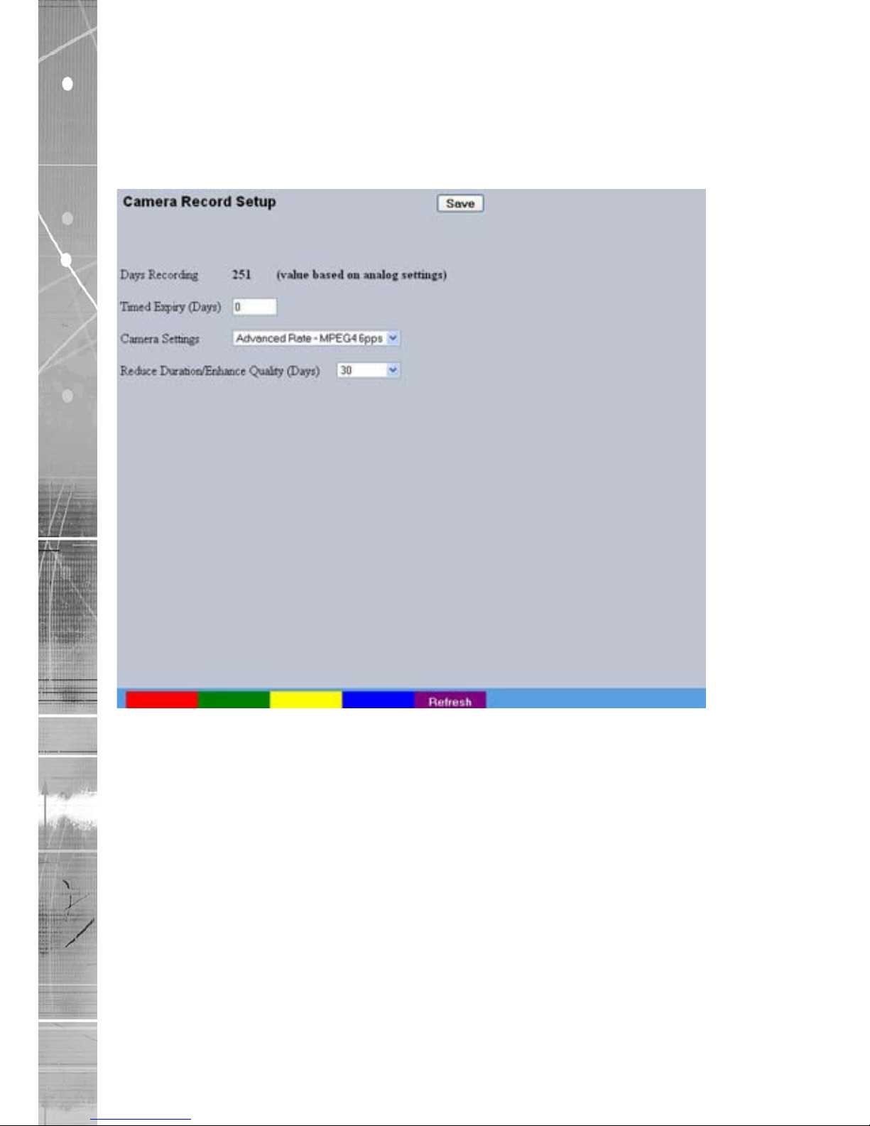
Record
The unit has a range of pre-dened congurations available. As standard the unit can record at 6pps
MPEG4 for up to 120 days (dependant on model). Alternatively the unit can be congured for 2pps
JPEG recording on each camera or for MultiMode operation (note that this will result in the record
duration being determined by the time period the unit is in alarm).
Days
Recording Displays the record duration possible using the
current conguration.
Camera Settings Choose the rate of non alarm recording to be used from the range
of preset recording proles. Select from Advanced Rate MPEG4
6pps, Advanced Rate JPEG 3pps or MultiMode recording.
Record Duration/Enhance Quality The recording duration can be limited to a set number of days;
allowing the recording quality to be enhanced for a shorter
storage period.
Page 57

Dedicated Micros ©2009
57
SD Advanced
Prole Record
It is possible to set the unit recording conguration based on specic priorities.
The MultiMode
recording feature offers the ability to set different recording rates, resolutions and compression
formats across unset, set and override modes for each individual camera. By varying the quality, bit
rate and le size of recorded images, the MultiMode function enables the recording capabilities of
the unit to be greatly increased. The Prole record menu can be accessed in a Simple format or in
Advanced mode. The Advanced mode offering greater opportunities to dynamically edit individual
cameras recording capabilities.
Simple Record
Menu View Switch to the Advanced Prole Record menu.
Days Recording Displays the record duration possible using the current
conguration.
MPEG4 Compression If using MPEG4 recording, edit the number of P-Frames recorded
before a new I-Frame (keyframe) will be taken for all cameras.
Note: Taking a new I frame once per second when recording above 5pps is recomended.
When the unit rewinds and fast forwards through recorded video, it will access I
frames only (and skip P frames). Having too long an interval can make viewing the
images in these modes difcult to follow. Note however that too short an interval will
reduce the benets of lower bit rate MPEG4 recording.
Page 58

Dedicated Micros ©2009
58
SD Advanced
Max Collection Resolution Setting the Max Collection Resolution limits the unit to record
within the following maximum resolutions across all cameras:
CIF global pps at a maximum 400pps.
2CIF global pps at a maximum 200pps.
4CIF global pps at a maximum 100pps.
Lowering the resolution settings will signicantly lessen the
storage capacity requirements.
Channel Enables selection of a specic camera for editing.
Copy To End Select to copy the current prole record settings to all camera
channels.
Copy To Next Select to copy the current prole record settings to the next
camera channel.
Pre-Trigger (JPEG) Enablng the Pre-Trigger feature will buffer and store alarm
recording prior to an event trigger (in JPEG format). It will use
the maximum available memory dependent on other cameras
requirements of the buffer space. Select ‘Enable’ to activate.
Note: It is recommended that the Pre-Alarm option in the ‘Alarm Settings-Zone Input’ menu be set
to the same value as the Pre-Trigger setting. This will ensure successful playback of high
quality Pre-Trigger images. High quality pre-trigger images will only playback properly if
review (playback) starts prior to the pre-trigger initiation.
Pre-Trigger Duration (secs) The Pre-Trigger Duration is the maximum possible time that data
will be stored prior to an event trigger.
Unset/Set/Override Normal Shows the recording prole used by the camera if no Timer
Functions are applied and the camera is operating under Normal
(non Event) conditions. Refer to the ‘Schedules’ section for further
details.
Unset/Set/Override Event Shows the recording quality that will be used by the camera
during an Alarm or Event. Note that Set and Override schedules
will be used only when Timed Schedules are applied. Refer to the
‘Schedules’ section for further details.
Comp Select image compression format (MPEG or JPEG).
PPS The accompanying dropdown list allows the number of frames
captured per second to be set.
The pictures per second (pps) option allows either 6, 5, 2, 1, 0.5,
0.25 or 0.1 pps to be recorded.
Pictures can also be recorded at ‘Real Time’ speed, ‘3/4 Real
Time’ or ‘1/2 Real Time’.
To disable record, choose the ‘No Record’ option.
Select ‘User Dened’ to use settings established in the Advanced
Prole Record menu.
Quality The accompanying dropdown list allows the quality of recorded
images to be set. Select from Maximum, Very High, High,
Medium, or Low. Select User Dened to use settings established
in the Advance Prole Record menu.
Note:
The higher the Quality setting, the greater the storage space used.
Page 59

Dedicated Micros ©2009
59
SD Advanced
Advanced Record
Menu View Switch to the Simple Prole Record menu.
Note: When Advanced Record settings have been changed, it is not possible access the Simple
Record menu until the newly congured Advanced Record settings have been applied. To
do this, open the Record menu and select the ‘Save’ option. It will then be possible to return
to the Prole Record menu and access Simple Record.
Days Recording Displays the record duration possible using the current
conguration.
Max Collection Resolution Setting the Max Collection Resolution limits the unit to record
within the following maximum resolutions across all cameras:
CIF global pps at a maximum 400pps.
2CIF global pps at a maximum 200pps.
4CIF global pps at a maximum 100pps.
Lowering the resoluion settings will signicantly lessen the storage
capacity requirements.
Channel Enables selection of a specic camera for editing.
Copy To End Select to copy the current prole record settings to all
camera channels.
Copy To Next Select to copy the current prole record settings to the next
camera channel.
JPEG Pre-Trigger Rate (pps) The Pre-Trigger feature will buffer and store alarm recording prior
to an event trigger (in JPEG format). It will use the maximum
available memory dependent on other cameras requirements of
the buffer space. Enter the record rate (in pps).
Page 60

Dedicated Micros ©2009
60
SD Advanced
Unset/Set/Override Normal Shows the recording prole used by the camera if no Timed
Schedules are applied and the camera is operating under Normal
(non Event) conditions. Refer to ‘Schedule’ for further information.
Unset/Set/Override Event Shows the recording quality that will be used by the camera
during an Alarm or Event. Note that Set and Override schedules
will be used only when Timed Schedules are applied. Refer to
‘Schedule’ for further information.
Comp Select image compression format (MPEG or JPEG).
Res Select image resolution format (QCIF, CIF, 2CIF or 4CIF).
Rate_kbps If MPEG4 is selected, the gure entered here will be the bit rate
allocated. A higher bit rate will provide better quality. MPEG bit
rates can be entered within the range of 45-2500K bits/second.
Size If JPEG is selected, the gure entered here will be the size of the
JPEG transmitted (in Kbytes). JPEG le sizes can be congured
within the range of 5-45Kbytes.
PPS Select the number of pictures recorded per second.
GOP If using MPEG4 recording, select the number of images
recorded within a GOP (Group of Pictures). A GOP consists of
an I-Frame (keyframe) and following P frames.
Page 61

Dedicated Micros ©2009
61
SD Advanced
IP Record
This menu enables the conguration of IP camera record settings.
Note: There is only normal ‘non event’ recording for connected IP cameras.
Channel Enables selection of a specic I.P camera for editing. Only
cameras designated as I.P will be available.
Copy To All Select to copy the current record settings to all connected IP
cameras.
Unset/Set/Override Normal This column shows the recording prole used by the camera when
operating under Normal (non Event) conditions.
Comp Select image compression format (MPEG or JPEG).
Res For both MPEG and JPEG recording, select either High, Medium
or Low quality resolution settings.
Note: To view a local IP camera ‘live’, IP recording should be set to MPEG.
Page 62

Dedicated Micros ©2009
62
SD Advanced
Schedule
This menu allows the Timer Function to be congured. The Timer Function enables the unit to
automatically be put into set/unset mode at specic times on specic days. This can help reduce
unnecessary alarm triggers.
When the unit is in Set or Unset mode, combine with different recording qualities and rates under
normal and alarm conditions for a high degree of control in a range of situations.
Note: If Keyswitch is Enabled, the Day Time and Night Time options will not be displayed. The
additional Keyswitch options will instead be displayed.
Mode/Title Enables a name to be entered for Unset, Set and Override mode.
Current Mode Shows the current timer mode according to the names entered in
the Mode/Title text boxes.
Day Time Enter the time (using the 24hr clock) when Unset mode will begin.
Night TIme Enter the time (using the 24hr clock) when Set mode will begin.
Keyswitch A Keyswitch can be used to switch the recording prole (Unset/
Set), If required, select ‘Enable’ then choose a contact to be used
in a specic zone as the Keyswitch.
Note: When the Keyswitch option is set to ‘Enabled’. It is necessary to save (or exit and return to)
the menu. The additional Keyswitch options will then be displayed.
Page 63

Dedicated Micros ©2009
63
SD Advanced
Keyswitch-N/O Select whether the Keyswitch is to be normally open (UNSET)
Keyswitch EOL Select to congure the Keyswitch for EOL. The End Of Line
(EOL) option enables the Keyswitch to detect any changes in the
electronic input resistance. A change outside the expected values
will result in a Tamper Alarm (short circuit or open circuit) being
detected and the system switching to alarm mode.
Page 64
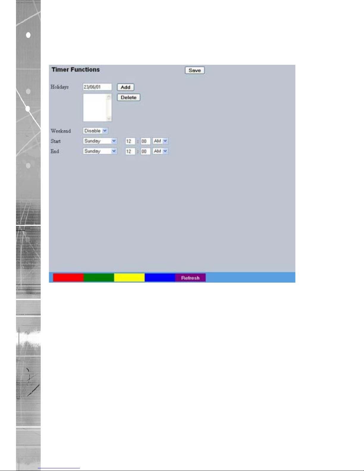
Dedicated Micros ©2009
64
SD Advanced
Holiday & Weekend
This menu allows the unit to be automatically switched to Override mode for individual days i.e.
public holidays or during a weekend (or any dened period).
Holidays Enter a date and press the Add button. The date will be added to
the Holiday list. To delete, highlight and select Delete.
Weekends Select ‘Enable’ to activate the Weekend function. Set mode will
now be active for the dates outlined below.
Start Select a Start day and time for Weekend mode.
End Select an End day and time for Weekend mode.
Note: Weekend mode will remain activate each week until deselected.
Page 65

Dedicated Micros ©2009
65
SD Advanced
Protect Video
This menu allows the unit to automatically protect and retain recorded data. Previously saved data
can also be unprotected. Enter a start and end time and select ‘Reload List’ . All saved video les
from the chosen time period will be shown in the upper textbox. These recorded ‘PAR’ les can then
be selected and protected via their accompanying checkboxes and the Protect option. Selected
video les can also be unprotected via the Unprotect option.
The lower textbox provides a status report detailing which video les have been
protected/unprotected.
Start Date Enter a start date to protect video.
Start Time Enter a start time to protect video.
End Date Enter an end date to protect video.
End Time Enter an end time to protect video.
Protect Length (days) Enter the number of days that selected les will be protected for.
Protect Select this option to protect recorded video for the selected
time period(s).
Unprotect Select this option to unprotect recorded video selected from
the list.
Reload List This will refresh the video list according to the selections made in
the Start Time/Date and End Time/Date dialog boxes.
Select None This de-selects all the available video les.
Page 66

Dedicated Micros ©2009
66
SD Advanced
Select All This selects all the available video les.
List From Date/Time This dialog box allows a search to be made within the protected
video list starting from a specic Time and Date.
List To Date/Time This dialog box allows a search within the protected video list to
conclude at a specic Time and Date.
Page 67

Dedicated Micros ©2009
67
SD Advanced
Alarm Settings
The Alarm Settings menus allow conguration of the unit’s alarm functionality. Individual alarm inputs
and alarm zones can be congured. Global relays can be activated and the Activity grid set up.
Refer to the individual menus for further details.
The Alarm Input page allows conguration of alarm channels. Up to 20 alarm channels are available.
The Zone Input page enables the conguration of alarm zones. Up to 32 separate alarm zones can
be created.
The Zone Actions page enables actions such as Go to Preset or Archiving to be allocated to alarm
zones. Zones can also be associated with a specic camera. On receipt of an alarm, images from
the associated (primary) camera will automatically be displayed in the Viewer menu.
The VMD/Activity Response page enables conguration of responses following an VMD/Activity
Detection trigger.
The Activity Setup page allowed activation and conguration of the Activity feature on all video
inputs. The Activity feature enables cameras to automatically detect any movement/changes within
the video scene. This can trigger a number of operations such as FTP alarm notication or an
increase in the recording rate.
The VMD Conguration page enables the unit’s VMD (Video Motion Detection) to be set-up. VMD
allows a camera to automatically detect if there is any movement/changes within specic areas of
the video scene.
The Global Relays page allows the four onboard relay connections and global relay settings to be
congured.
Page 68
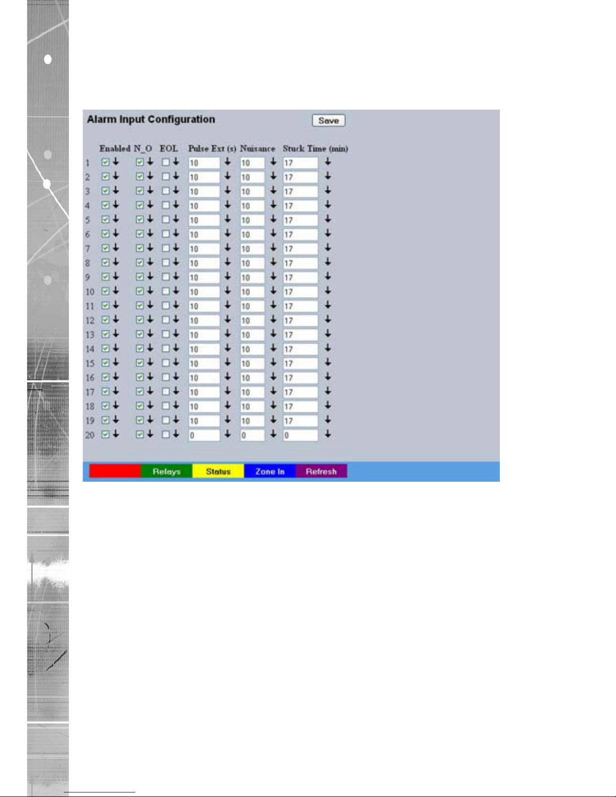
Dedicated Micros ©2009
68
SD Advanced
Alarm Input
This menu allows conguration of the alarm settings, refer to ‘Installing the Unit’ for hardware
installation guidance.
Number This identies which input is being congured. The unit supports
20 on-board alarms.
Enabled Each input must be enabled to function. If the input is not enabled
and an alarm is received, the unit will not acknowledge the alarm.
N_O (Normally Open Contact) N_O indicates the non-alarm state of the input. Tick the N_O
checkbox to set the corresponding input to Normally Open. The
alarm will then trigger when the input is closed (shorted). If left as
Normally Closed (the default setting), the alarm will trigger when
the input is opened.
Note: If EOL alarms are to be used, this option should not be selected i.e. leave set as
Normally Closed.
EOL The End Of Line (EOL) option enables the inputs to detect any
changes in the electronic input resistance. A change outside the
expected values will result in a Tamper Alarm (short circuit or open
circuit) being detected and the system switching to alarm mode.
Page 69

Dedicated Micros ©2009
69
SD Advanced
Pulse Ext A pulse extension is used to prevent double triggers on a single
alarm. The pulse extension time starts on an alarm trigger. If that
contact is triggered again after the rst alarm has nished but
within the pulse extension, the second trigger will not restart the
alarm, but will extend the current alarm duration. Enter the time in
seconds for this extension.
Nuisance This is a repetitive detector value. When an alarm is received on
the unit, it will store the alarm time and monitor the number of
times the same detector is triggered within an hour period. If the
detector is triggered the number of times entered here, the unit
will de-activate this detector from triggering an alarm for an hour.
The unit will continue to monitor the detector and check how many
times it is triggered during this period. If it is again triggered more
than the amount set in the nuisance counter, it will remain de-
activated for another hour. This will continue until the trigger value
falls below the nuisance count setting. To disable this feature,
leave the setting as ‘0’.
Stuck Time If any of the alarms/detectors are active for a period longer than
specied here, they will automatically be omitted. This time period
is set in minutes.
Note: The arrow button displayed next to each textbox allows settings to be replicated for those
cameras listed below. This will only affect the adjacent option i.e. Enabled arrow will
replicate the Enabled setting to cameras below the clicked arrow.
Page 70
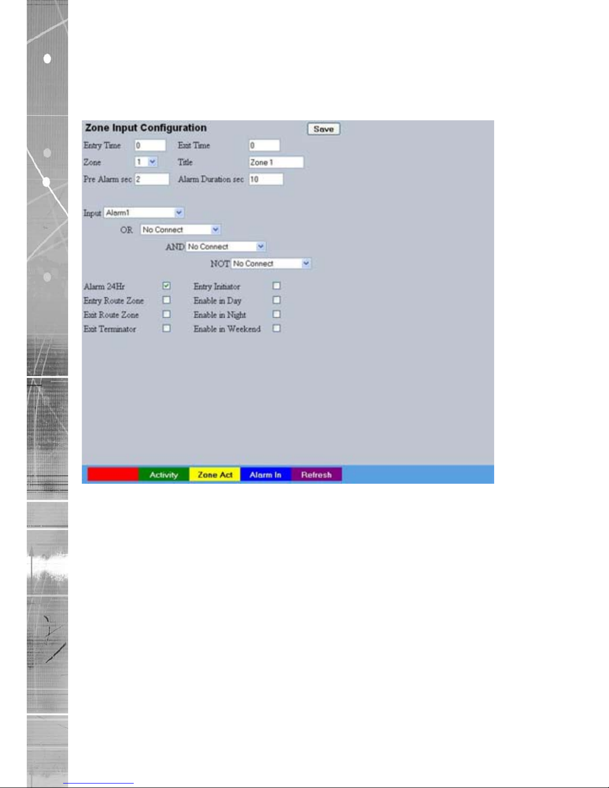
Dedicated Micros ©2009
70
SD Advanced
Zone Input
This menu allows the conguration of established alarm zones. A single or multiple trigger can be
used to generate an alarm. It is possible to allocate up to 32 alarm zones to carry out a combination
of actions. Use these options in conjunction with the Zone Actions menu.
Entry timer This is the number of seconds allowed for the user to enter the
zone and disable the alarms. If the alarm is not disabled within
this period the alarm will be triggered.
Exit timer This is the number of seconds from the alarm being set within
which the user must exit the set zone. If the user is still within the
zone after this time period the alarm will be triggered.
Zone An alarm zone can be established to logically groups alarms
and initiate actions when an alarm is activated, there are 32
congurable zones.
Title This information is stored along with the relevant images in the
database, ensure this has relevance to the alarm zone.
Pre-Alarm sec This is the time period prior to the start of the alarm included
with the alarm recording for archive. These images will also be
protected from being overwritten.
Note: It is recommended that the Pre-Alarm option be set to the same value as the Pre-Trigger
setting in the “Prole Record“ menu. This will ensure successful playback of high quality
Pre-Trigger images. High quality pre-trigger images will only playback properly if review
(playback) starts prior to the pre-trigger initiation.
Page 71

Dedicated Micros ©2009
71
SD Advanced
Alarm Duration sec This is the minimum time period in seconds (from the start of
the alarm) that is protected from being overwritten. This time will
include the alarm trigger, the pulse extension and any post alarm
recording. It will not include pre-alarm images.
Zone Input Rule This determines which input(s) will trigger the zone alarm:
Input This sets an input or system function as the primary alarm trigger.
Select from Alarms 1-32, Activity 1-16, Preset 1-16, Disk Low,
Disk Full, Panic, Archiving Slow, Archiving Fault, Virtual 1-16, and
Keyword Channel 1-32 (which will trigger the Alarm if any or the
32 programmed keywords are detected on the selected channel).
Zone OR Input The Zone OR Input identies an alternative input that can also be
used to trigger the zone alarm. This means an alarm trigger can
be received on the Zone Alarm Input or the Zone OR Input for the
zone to be activated.
Zone AND Input
The Zone AND Input identies that an alarm trigger needs to be
received on both the Zone Alarm Input and the Zone AND Input
for the zone to be activated and the alarm action to the
automatically initiated.
Zone NOT Input
The unit will only issue the alarm actions if the trigger is received
on the zone alarm input and NOT on the Zone input.
Alarm 24Hr This option can be enabled for alarms that do not require change
at any time and are to remain as programmed i.e. Panic Alarm.
When this is selected, the Set, Unset and Override options
are disabled.
Entry Route Zone This creates deferred alarms along a specied route while the
entry time is active. This is in compliance with BS8418 (the British
Standard for remote video reporting centres). Diverting from the
entry route during the countdown will result in the alarm being
triggered immediately. This allows staff entry without triggering an
alarm prior to switching the system to Set mode.
Exit route Zone This creates deferred alarms along a specied route while the
exit time is active. This is in compliance with BS8418 (the British
Standard for remote video reporting centres). Diverting from the
exit route during the countdown will result in the alarm being
triggered immediately. This allows staff to exit without triggering
an alarm.
Exit Terminator This will trigger the exit timer if the system is set. A countdown
timer will automatically start when the alarm is activated and
ensure the alarm system is not activated by other specied alarm
triggers for the Set time i.e. allowing a Guard to exit a building.
Entry Initiator This will trigger the entry timer if the system is set. A countdown
timer will automatically start when the ‘primary’ alarm trigger
i.e. front door, is actioned. This ensures the alarm system is not
activated by other specied alarm triggers for the set time
Enable in Unset Each alarm can be congured to be active when the unit is in
a specic operation mode. Enable this for the zone alarm to be
active in Unset operation mode.
Enable in Set Each alarm can be congured to be active when the unit is in
a specic operation mode. Enable this for the zone alarm to be
active in Set operation mode.
Enable in Override Each alarm can be congured to be active when the unit is in
a specic operation mode. Enable this for the zone alarm to be
active in Override operation mode.
Page 72
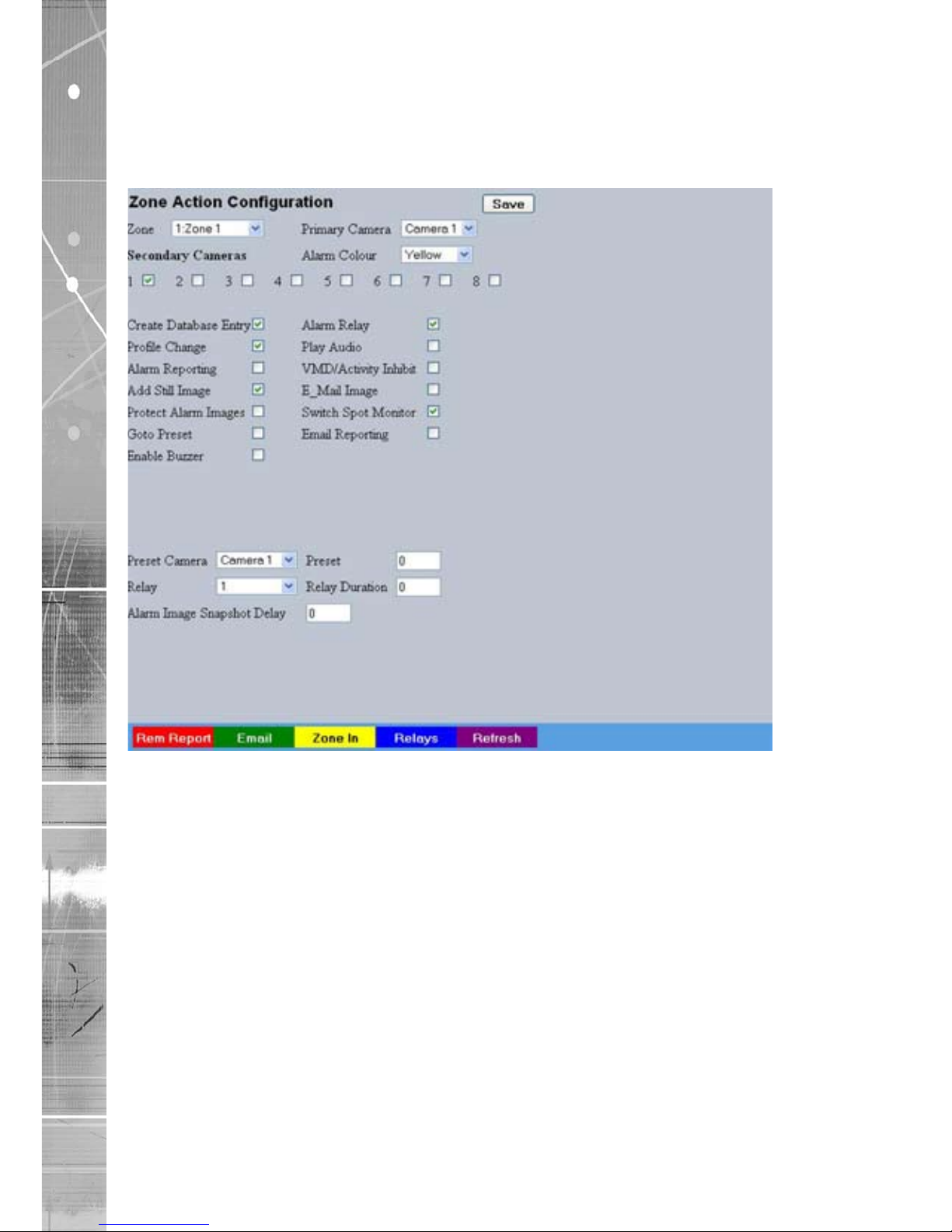
Dedicated Micros ©2009
72
SD Advanced
Zone Actions
This menu allows actions to be allocated to individual alarm zones; Primary and Secondary cameras
can be allocated to the zone and actions undertaken following alarm activation. This page should be
congured in conjunction with the Zone Inputs menu.
Zone Select a zone (alarm) to congure.
Primary Camera This allows a camera to be assigned as the primary camera
associated with the Alarm Zone. The primary camera will be
displayed when an alarm in this zone is triggered.
Alarm Colour This displays the local alarm text in the selected colour and can
be useful in prioritising alarms. Options available are Red, Green,
Blue, Yellow, Cyan and Magenta.
Secondary Cameras This setting gives the facility to assign additional cameras to the
zone. These cameras will become part of the alarm sequence
shown in the Viewer menus when the alarm zone is triggered.
Create Database Entry An alarm activation will be added to the database. The zone title
will be used as part of the entry information.
Alarm Relay Select to trigger an alarm relay following zone activation. Select
the specic relay via the ‘Relay’ option.
Prole Change Select to enable the unit to switch from Normal to Event recording
following alarm zone activation.
Play Audio It is possible to play associated audio upon zone alarm activation.
Alarm Reporting This must be enabled to allow the unit to send an alarm
notication to an external destination i.e an RVRC reporting via
NetVu ObserVer.
Page 73

Dedicated Micros ©2009
73
SD Advanced
VMD/Activity Inhibit Select to inhibit (ignore) the VMD/Activity detection feature. Refer
to ‘Activity Setup’ for more information.
Add Still Image This will record a still image of the trigger along with the standard
recording. This can then be sent on to an external destination.
Email Image If this option is selected, a JPEG will be added to the reporting
email (if Email Reporting is selected).
Protect alarm Images
Alarm images can automatically be protected from
being overwritten
.
Switch Spot Monitor Select to display the alarm zone Primary camera on the
Spot Monitor.
Goto Preset It is possible to action a camera to automatically be sent to a
preset position when an alarm is triggered.
Email Reporting The unit can send an email when an alarm is detected, refer to
‘Network-E-mail’ for more information.
Enable Buzzer Select to activate the unit’s internal buzzer upon alarm receipt.
Preset Camera The preset camera is the camera which will be sent to a
designated preset position upon alarm activation.
Preset Enter the preset position number for the selected camera here,
refer to ‘Unit Operation-PTZ Program’ for more information on
establishing camera preset positions.
Relay Select an onboard or external relay to automatically close on
receipt of an alarm.
Relay Duration Enter (in seconds) how long the relay is to remain closed.
Alarm Image Snapshot Delay This gure allows a delay to be introduced before an alarm
snapshot is taken. This is used when the alarm relates to a PTZ
camera which has to travel to a preset position.
Page 74

Dedicated Micros ©2009
74
SD Advanced
VMD/Activity Response Setup
This menu enables response conguration following activity trigger on a selected camera channel.
Channel Select the camera input for conguration from the drop down list.
Detection Type Each camera input can be congured for either ‘VMD’ or ‘Activity’
detection. To assign no detection settings to the camera, select
‘None’
Note: Whichever Detection option is selected here, will result in the camera channel being only
available for editing in the relevant conguration menu i.e. if Activity is selected for Channel
1;
this channel can only be edited for Detection in the Activity Setup menu and not the VMD
Conguration menu.
Activity To Trigger Following Activity activation, select ‘Simple Response’ to trigger
specic chosen responses from the options detailed below. Select
‘Zone’ to apply the Zone Input rules as congured in the Zone
Input menu. Refer to ‘Zone Input’ for more information.
Note: When Activity to Trigger is set to ‘Zone’; the options detailed below are unavailable.
Copy To All Select to copy the current Activity Response settings to all
camera channels.
Create Database Entry When selected, an alarm entry will be added to the
Event database.
Prole Change Select to enable the unit to switch from Normal to Event recording
following alarm activation.
Alarm Reporting This must be enabled for the unit to automatically connect
on alarm.
Page 75

Dedicated Micros ©2009
75
SD Advanced
Alarm 24Hr This will ensure that Activity Detection is permanently enabled on
this camera channel.
Add Still Image This will record a still image of the trigger along with the standard
recording. This can then be sent on to an external destination.
Protect Alarm Images Select to automatically protect alarm images from
being overwritten.
Switch Spot Monitor Enable this option to display alarm activated cameras on the
connected Spot Monitor.
Enable in Day This will enable Activity Detection when the unit is in Day (Unset)
operation mode.
Enable in Night This will enable Activity Detection when the unit is in Night (Set)
operation mode.
Enable in Weekend This will enable Activity Detection when the unit is in Weekend
(Override) operation mode.
Page 76

Dedicated Micros ©2009
76
SD Advanced
Activity Setup
The unit supports Activity Detection on all video inputs. It enables cameras to automatically detect
any movement/changes within the video scene; this can trigger a number of operations such as FTP
alarm notication and an increase in recording rate.
A still image of the selected camera will be shown in the Grid Editor screen. To establish an Activity
zone, edit the cells displayed across the image.
This option should be used in conjunction with the Zone Inputs and Zone Actions menus.
Global Activity Mode Three options are available for Activity activation (specically in
relation to a PTZ camera).
Selecting ‘Active while at Preset 1’ will result in Activity mode
functioning only when the camera is at preset position 1. Select
‘Active while camera not in motion’ for Activity mode to function
only when the camera is still. Select ‘Always Active’ for Activity
mode to be in constant operation.
Activity Channel This is a drop down list of the video inputs on the unit, selecting
an input will display images from the corresponding video source.
Grid Editor Use the Grid Editor by placing cells in areas of the camera view
where movement will trigger an alarm. To enter cells navigate
across the image via the Directional buttons of the I.R Remote
Control). If viewing on a local monitor place a cell by pressing
the OK button. If viewing via the webpages, use the mouse to
navigate across the image, use the left mouse button to
place a cell.
Reload Img (Red) This option will update the still image displayed in the Grid Editor.
Page 77

Dedicated Micros ©2009
77
SD Advanced
Set All (Green) This option will insert a default square of 16 x 16 cells across the
displayed video image.
Clear All (Yellow) This option will clear all entered cells.
Edit Mode Leave as ‘Normal’. Different Edit Mode functions will be added
following future development.
Edit Action Select ‘Invert’ to change the current grid state i.e. Clear to Set.
Select ‘Clear’ to remove grids or select ‘Set’ to add grids.
Activity Sensitivity This option allows the sensitivity setting to be established for the
activity grid being congured. There are ve settings to choose
from: Indoor High, Indoor Low, Outdoor High, Outdoor Low,
Very Low.
Page 78

Dedicated Micros ©2009
78
SD Advanced
VMD Conguration
The unit supports VMD (Video Motion Detection) on all video inputs and allows cameras to
automatically detect if there is any movement/changes within the video scene.
Note:
Video Motion Detection enables a greater degree of control over detection settings and
conguration than the Activity Setup function. Each of the 16 VMD Zones can be directly
sized and congured to suit specic requirements. VMD can only be accessed and
congured remotely via the webpages.
Function Description
Camera This is a drop down list of the video inputs on the unit, selecting
one of the inputs will display the corresponding video source.
Ensure this corresponds with the selected Channel.
Zone There are 16 VMD zones within the image that can be individually
congured, select the zone from the drop down list.
A selected zone can be re-sized by clicking the mouse button (use
the USB mouse if viewing on a local monitor) and then moving
and clicking the mouse again. A rectangle will then be displayed
based on these two selected points.
Page 79

Dedicated Micros ©2009
79
SD Advanced
Mode The zone mode identies when the reference image is taken for
triggering VMD. The options are:
Normal - The reference image is updated approx
every second. This will only allow small
changes in the scene without triggering
Last trigger - The reference image is only updated
when the VMD is triggered and is best
used under controlled lighting, i.e.
so there are no false triggers due to
ambient light changes.
Static - The reference image is collected on
startup and is never updated. This
would be used in ‘sterile’ areas where
there are no changes expected.
Zone disabled - This will disable the zone mode.
Pixel Count (%) This value is set as a percentage and equates to the percentage
of pixels in the selected zone that must change for the VMD event
to be triggered. The default setting is 20%.
Pixel Change (%) This setting is a percentage value of the overall change required
in the grayscale to be included in the pixel count. The percentage
change is dened over the complete range of black to white, a
100% pixel change would be from black to peak white. The default
setting is 20%.
Reload Image (Red) This will update the reference image to the latest view during
set up.
Clear All (Green) Removes all dened zones from the image.
Default Grid (Yellow) Displays the default 16 zone grid across the whole image.
Page 80
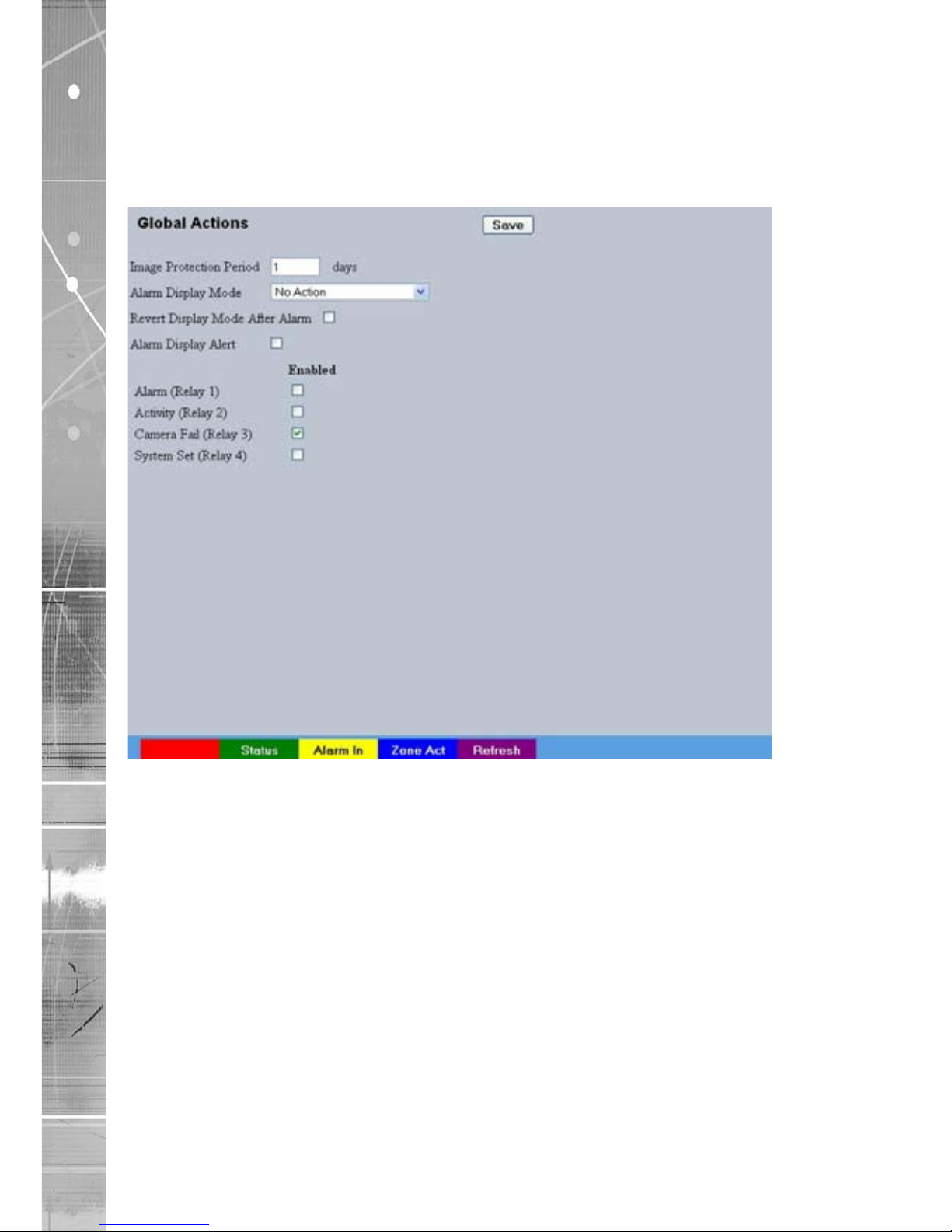
Dedicated Micros ©2009
80
SD Advanced
Global Actions
This menu details how to congure the default relay actions supported on the unit.
The unit supports four onboard relay connect
ions and global relay settings. These global relays can be
trigge
red under specic conditions i.e. on receipt of any alarm or any notication of
Activity
Detection
.
Image Protection Period Select a time period (in days) that images associated with an
alarm will be protected from deletion.
Alarm Display Mode When a relay has been triggered, the primary camera associated
with that relay can immediately be displayed on the local monitor.
Select ‘Jump To Primary Camera’ from the drop down list to
activate this function.
Revert Display Mode after Alarm Enable this setting to make the unit return to the view displayed
before the alarm activation.
Alarm Display Alert Enable this setting to display an alarm text alert in the colour
specied in ‘Alarm Colour’ in the Zone Actions Menu.
Alarm (Relay 1) Select this option to establish any alarm trigger as a Global Relay.
Therefore the relay will close when an alarm is received on any of
the alarm inputs.
Activity (Relay 2) Select this option to establish any Activity Detection trigger as
a Global Relay. Therefore the relay will close when Activity is
identied on any of the camera inputs.
Page 81

Dedicated Micros ©2009
81
SD Advanced
Camera Fail (Relay 3) Select this option to establish any camera fail trigger as a Global
Relay. Therefore the relay will close when there is notication
on the system that any of the enabled video inputs has camera
failure (no 1V pk-to-pk signal).
System Set (Relay 4) When selected, the unit will automatically switch to Set mode
following relay activation.
Page 82

Dedicated Micros ©2009
82
SD Advanced
Network Settings
The Network Settings menus allow conguration of the unit’s network functionality. Key network
settings can be established such as ‘xing’ the unit’s IP address and maximum transmission rate.
E-mail, remote reporting on alarm and FTP download can also be congured. Refer to the individual
menus for further details.
The Network Settings page allows conguration of the unit’s network connections such as the name
assigned to the unit and its IP address.
The Live Transmission page enables JPEG and MPEG proles to be created for transmitting images
via a High, Medium or Low quality network connections to any viewing software or to another unit
using this one as an IP source..
The Email page allows conguration of the Email feature. The unit can automatically transmit an e-
mail to an SMTP Server following an event i.e. on receipt of an alarm or a camera failure notice.
The Remote Reporting page allows a Remote Video Receiving Centre’s (RVRC) conguration
details to be entered. The RVRC will then be contacted following a selected event occurring i.e.
reported alarm or camera failure.
This Firewall page allows the user to block access to the unit via specic network port(s).
Page 83
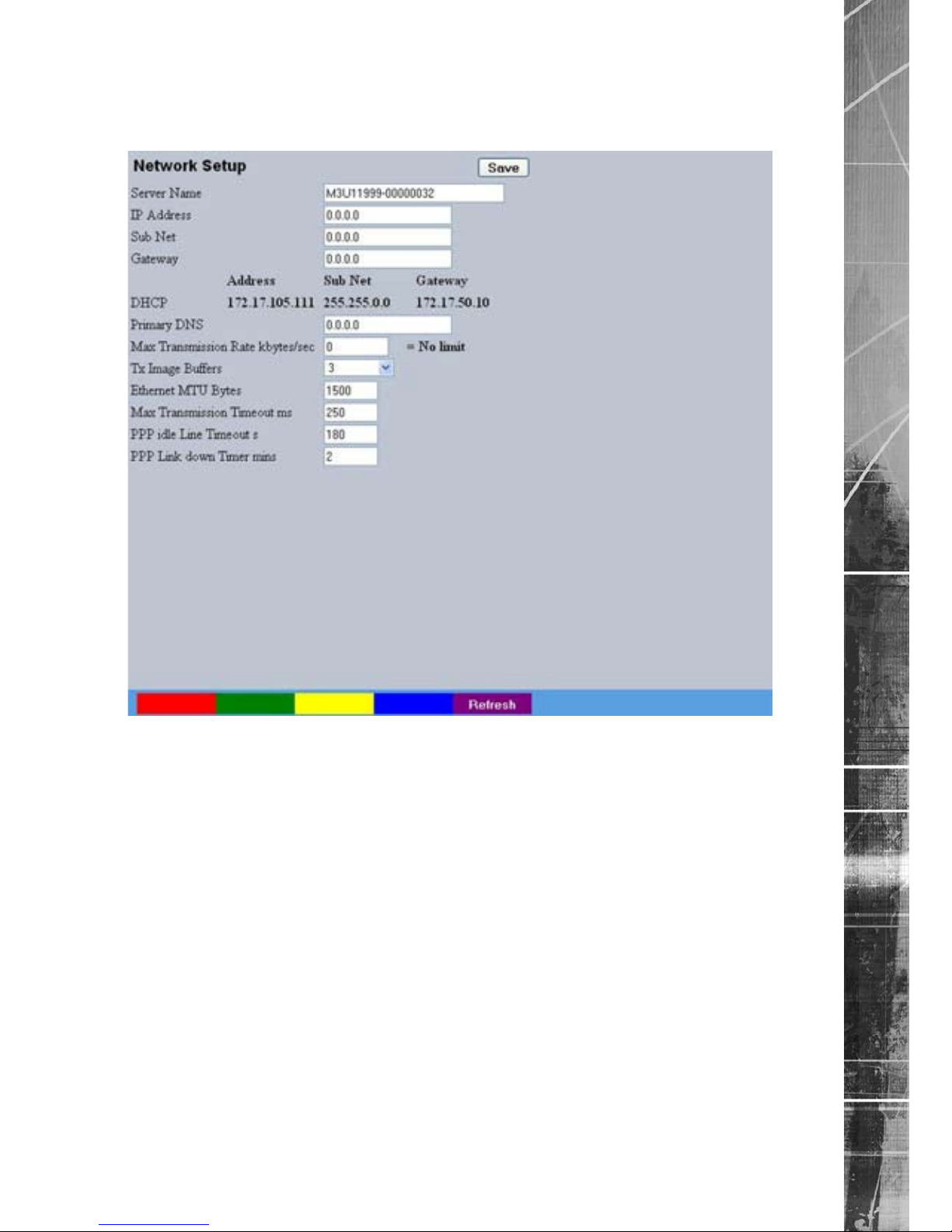
Dedicated Micros ©2009
83
SD Advanced
Network
This menu allows additional network settings to be congured if required.
Server Name This eld can be edited to allocate a name to the unit. This
would be used if accessing the unit via a Domain Name
Server (DNS).
IP Address
This is the IP address allocated to the unit.
Sub Net This is the subnet of the network were the unit is located.
Gateway This is the IP address of the default gateway (router).
Primary DNS This is the primary DNS server IP address for applications utilising
domain names.
Max Transmission Rate Shows the maximum transmission speed for the network type.
Tx Image Buffers This is used in order to improve the picture delivery over Ethernet
when using a slow connection i.e. 256Kbps. A buffer setting of 1,2
or 3 is available.
Ethernet MTU This is the maximum transmit unit for the Ethernet packet. The
MTU is the largest physical packet size measured in bytes that the
network can transmit. By default this gure is set to 1500bytes.
Mx Transmission Timeout ms This is the time (in milliseconds) the unit will wait to re-send a
packet if an acknowledgement is not received.
Page 84

Dedicated Micros ©2009
84
SD Advanced
PPP Idle Line Timeout s This is the time (in seconds) the unit will wait before disconnecting
the PPP (Point to Point Protocol) link if data has not been
transmitted or received.
PPP Link Down Timer mins If for any reason the PPP connection is lost, this is the time (in
minutes) before the unit will be forced to drop the PPP connection.
Page 85
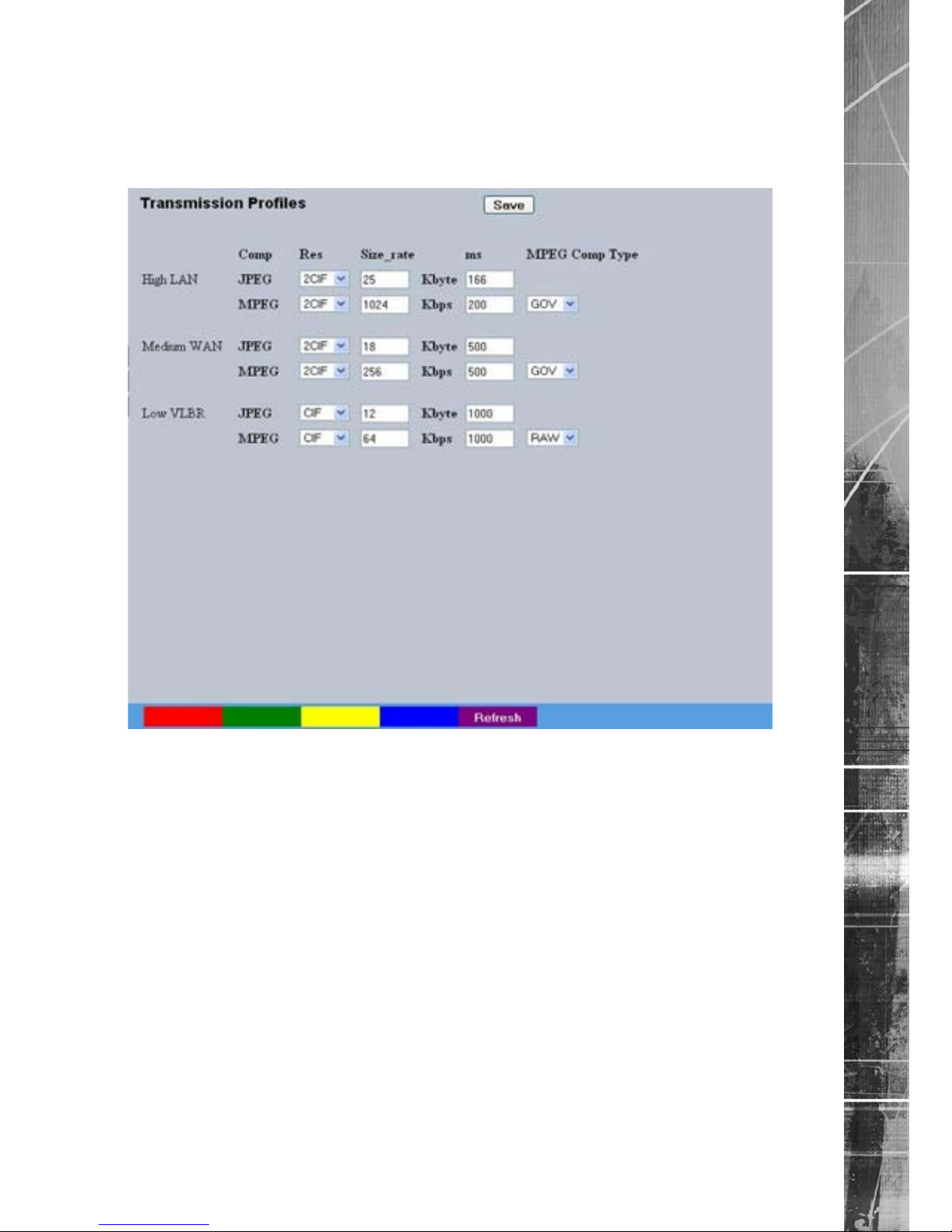
Dedicated Micros ©2009
85
SD Advanced
Live Transmissions
The unit transmits live images using JPEG or MPEG formats.
The NetVu Connected remote viewing software will use the settings congured on this page as the
defaults for JPEG & MPEG; High, Medium and Low settings.
High LAN/Medium WAN/Low VLBR This shows the transmission settings congured for a High quality
LAN (Local Area Network) connection, Medium quality WAN
(Wide Area Network) connection or a Low quality VLBR (Very Low
Bit Rate connection).
Comp Settings can be established for JPEG and MPEG compression
.
Res
For MPEG and JPEG transmission, select image resolution
settings (2CIF, CIF or QCIF).
Size_rate For JPEG, the gure entered will be the size of the JPEG
transmitted (in Kbytes). For MPEG4 the gure will be the bit rate
allocated. A higher rate will provide better quality picture display.
JPEG le sizes can be congured in the range of 5-45Kbytes and
MPEG bit rates in the range of 45-2500Kbits/second.
ms This shows the number of pictures transmitted per millisecond.
For JPEG, the actual images transmitted will depend on the
bandwith of the link, increasing the pictures sent per millisecond
may introduce time lag if bandwith is not sufcient. On MPEG
transmission, increasing the pictures sent will also reduce the
quality of the images (as more images are transmitted for the
dened bit rate).
Page 86

Dedicated Micros ©2009
86
SD Advanced
MPEG Comp Type Select whether transmitted MPEG4 images are sent as RAW
data or in GOV (Group of Video) format. RAW mode transmits a
single I frame and then a sequence of P frames (until a change in
transmission is detected). GOV mode sends I and P frames in a
standard format i.e. I to P frame
ratio as set by the record parameters.
Page 87
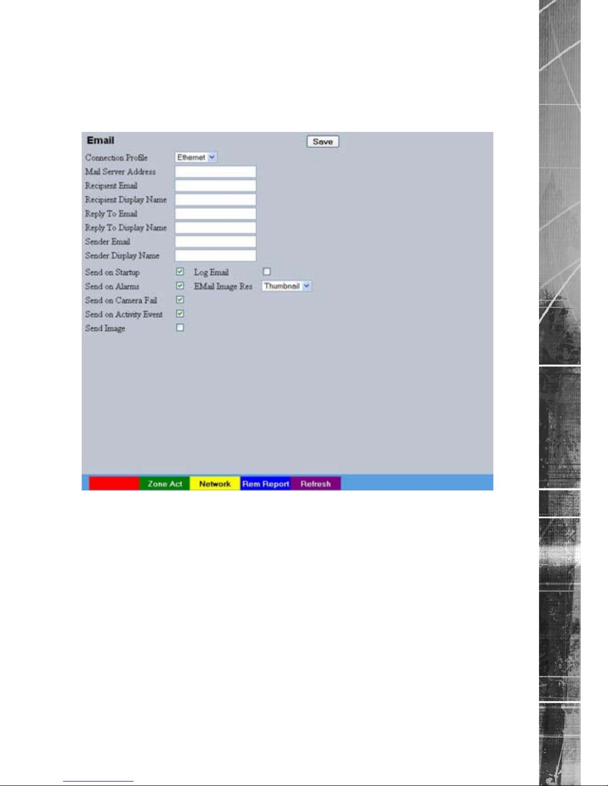
Dedicated Micros ©2009
87
SD Advanced
E Mail
The unit can automatically transmit an e-mail to an SMTP Server under numerous conditions i.e. on
start up, on receipt of an alarm, camera failure etc. This allows the unit to be installed in unmanned
applications where a Remote Video Response Centre (or Manager etc.) would be notied by e-mail
if any of these conditions occur.
Connection Prole It is possible for the e-mail to be transmitted via the Ethernet
network or dial up connection (PPP ‘Point to Point Protocol’).
This setting presumes that a modem has been connected or
congured and the unit is connected to a LAN or WAN and
allocated a valid IP address.
Mail Server Address This is the IP address or URL of the SMTP Server that the e-mail
will be sent to. The SMTP server will then forward this to the
intended recipient.
Recipient Email This is the e-mail address of the intended recipient.
Recipient Display Name This is the addressee name that will be shown in the email name
eld.
Reply to Email This eld must be congured if the recipient is to reply to an e-
mail. The unit does not accept incoming e-mails therefore ensure
this is a valid e-mail address.
Reply To Display Name This is the ‘reply to’ name that will be shown in the email
name eld.
Sender Email These optional elds indicate the source of the e-mail notication.
If the elds are left blank the unit will use the system name to
create a sender name.
Page 88

Dedicated Micros ©2009
88
SD Advanced
Display Name (Sender) This is the sender name that will be shown in the email
name eld.
Send on Startup Select to send email notication on startup.
Send on Alarms Select to send email notication on alarm activation.
Send on Camera Fail Select to send email notication on camera fail.
Send on Activity Event Select to send email notication on activation of the Activity
Detection feature.
Send Image Select to send accompanying image from supporting
primary camera.
Log Email Select to log every e-mail transaction that the unit issues.
Email Image Res Select resolution settings for images sent as ‘thumbnail’
attachments. Choose from: Thumbnail, LO (low res), MED
(medium res) and HI (high res).
Page 89
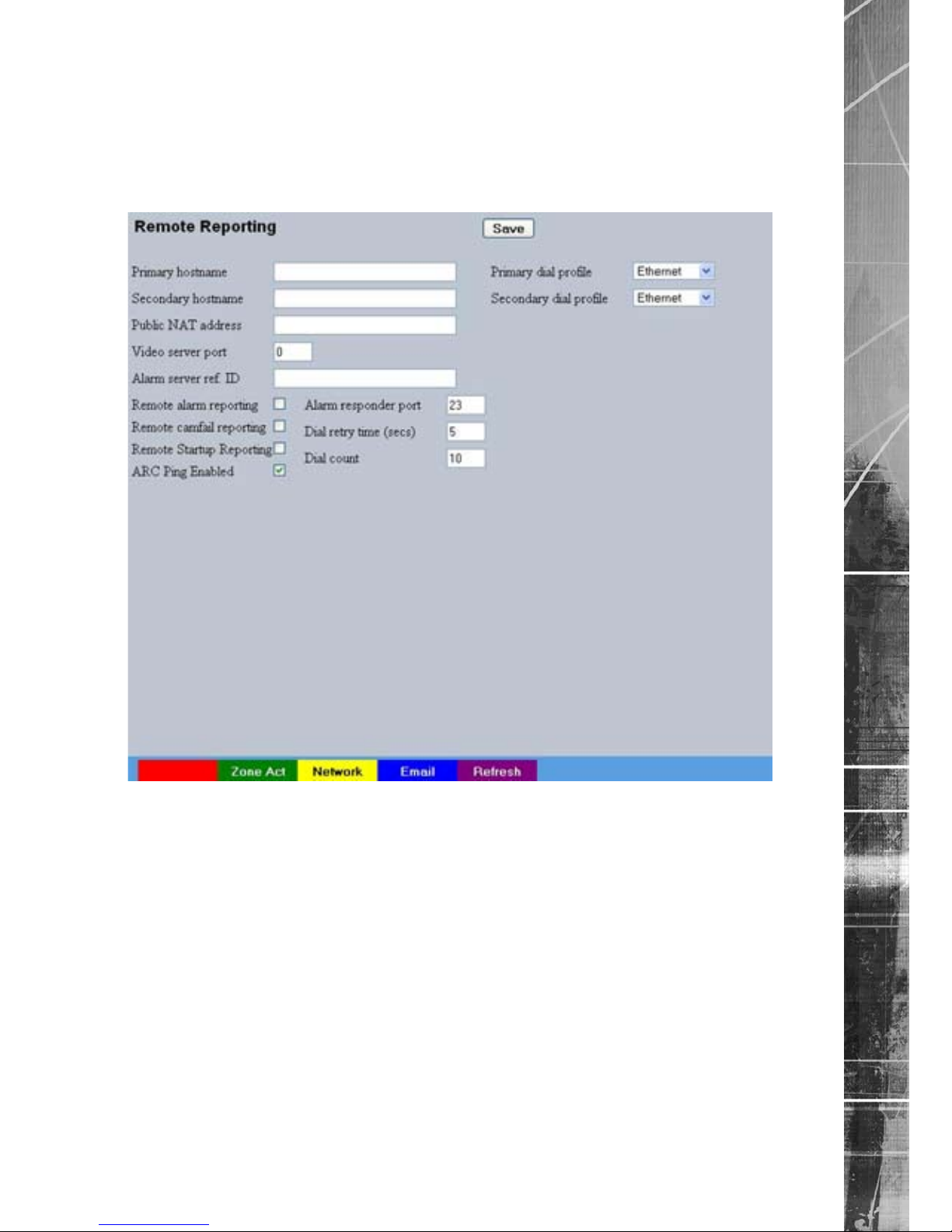
Dedicated Micros ©2009
89
SD Advanced
Remote Reporting
This menu details the conguration requirements for the unit to report to a Remote Video Receiving
Centre (RVRC) following alarm activation.
Note: This menu will only be displayed if ‘Remote Reporting’ is selected in the
System Settings->Features menu.
Primary Hostname This is the IP address or URL of the initial host that the unit will
transmit an alarm message to.
Primary Dial Prole It is possible for the alarm message to be transmitted via the
Ethernet network or a dial up connection.
Secondary Hostname If the unit is unable to contact the primary host, an alternative
route can be identied via a secondary host. If there is only one
alarm receiving IP address, you must enter the details in both the
primary and secondary connection settings.
Secondary Dial Prole It is possible to select a separate dial prole for the
secondary host.
Public (NAT) Address This is the public IP (or domain name) for a unit connected to
the Internet via a NAT Router or Firewall. This eld should be left
blank if NAT is not used e.g. a private network.
Video Server Port This eld allows the RVRC to connect to the unit through a router
that is using port forwarding e.g. if the video server does not
appear on port 80 (HTTP), to the external network. Enter the port
number used for forwarding here if required.
Page 90

Dedicated Micros ©2009
90
SD Advanced
Alarm Server ref. ID This is the reference name/ID that will be presented to the RVRC
viewing application. It should therefore have some signicance to
the Operator.
Remote Alarm Reporting This must be enabled for the unit to automatically connect
on alarm.
Remote Cam Fail Reporting Enabling this option ensures the unit reports camera failure on
any of the inputs to the RVRC.
Remote Startup Reporting This will send an alarm report when the unit starts up. Any system
resets will be identied.
ARC Ping Enabled
Should the modem/router at the Alarm Receiving Centre be dormant,
the unit will ‘Ping’ the ARC prior to sending reporting data.
Alarm Responder Port This species the network port number used for reporting to the
alarm server. In normal circumstances this should be left at the
default value (23).
Dial Retry Time (secs) If the initial connection attempt fails, the unit will wait for the
specied time period (in seconds) before attempting to re-connect.
Dial Count This identies the number of times the unit will attempt to connect
after a failed attempt. A setting of ‘0’ means no limit and the unit
will continue to try and connect until successful.
Page 91
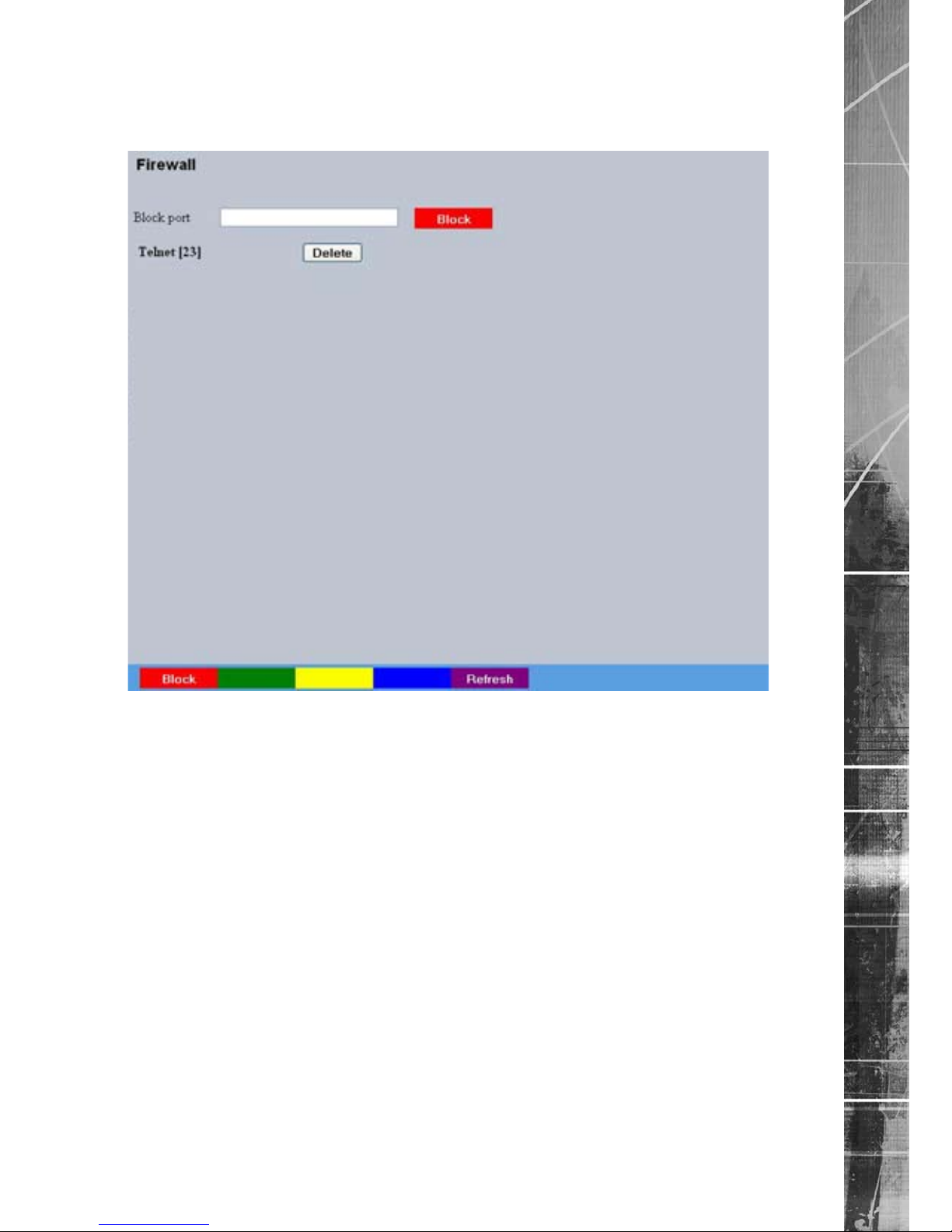
Dedicated Micros ©2009
91
SD Advanced
Firewall
This menu allows the user to block access to the unit via specic network port(s).
Block Port Enter the port number and select Block (Red).
Delete To unblock and allow access via a specic port, select the Delete
option next to the required port.
Page 92

Dedicated Micros ©2009
92
SD Advanced
Analytics & Text
The Analytics and Text menus allow conguration of the unit’s text in image and keywords
functionality, refer to the individual menus for further details.
The SD Advanced is AnalyticsCapable. Please call Dedicated Micros on + 44 (0) 845 600 9500 for
further information on our range of Analytics based solutions.
The Text In Image page allows the unit to integrate text data with recorded images i.e. a cash
register with a camera positioned at the point of sale.
The Keyword page can be used in conjunction with the Text in Image function. Keywords can be
entered, which when detected, will trigger an alarm. Up to 30 keywords can be created.
The Archive page allows Event database information to be downloaded to an inserted DVD/CD or
connected USB media device.
Page 93

Dedicated Micros ©2009
93
SD Advanced
Analytics
Dedicated Micros has created a range of analytics components and solutions designed to work with
the AnalyticsCapable SD Advanced. The range of applications include: Automatic Number Plate
Recognition (ANPR), Object Left and Removed, Access Control, People Counting and Perimeter
Protection.
• For further information regarding the range of Dedicated Micros Analytics solutions,
please call: + 44 (0) 845 600 9500
Page 94

Dedicated Micros ©2009
94
SD Advanced
Text In Image
It is possible to integrate the unit into a system were text information can be stored with relevant
images for review. This would be most useful in a Retail or Finance application were text data
originating from a cash register could be displayed in real time with the video images of the same
Point of Sale.
Note: This menu will only be displayed if ‘Text in Image’ is selected in the
System Settings->Features menu.
Recorded lines per frame This controls how many lines of text are stored on the server, and
not how many are displayed on screen. This allows more data to
be saved than is shown.
Text Timeout This setting controls how long, in seconds, the text is shown
onscreen (selecting 0 will show the text indenitely).
Channel Select the camera input for conguration from the drop down list.
Copy To All Select to copy the current text in image settings to all
camera channels.
Text Port Type Select the input source for Text in Image data. Select ‘Off’ to
switch the function off, select ‘Network to use the
unit’s Network
port or ‘Serial’ to use one of the unit’s serial ports (see
‘Port’ below).
Port All serial ports on the unit support the option for Text In Image.
For serial transmission ensure one of the serial ports is congured
appropriately, refer to System Settings->Serial Ports’. Select the
congured port from the drop down list.
Page 95

Dedicated Micros ©2009
95
SD Advanced
Text Filter Select the text lter option from the drop down list. The options
are: Plain Text (default), RAW, EPSON, Laserjet, DM POS
Receipt, DM POS Journal, TVC-1066
Line length This identies the length of the lines that will be stored with
the
image. The default setting is 20 characters i.e. typically
full screen.
Number Visible Lines To enable the text information to be viewed successfully, it is
necessary to establish how many lines of text will be visible
on screen.
Background Colour A black background box appears by default around the text. It is
possible to change the colour of this box. Select from the drop
down list.
Text Colour The colour of the displayed text can be changed. Select from the
drop down list.
Enable Keywords This enables or disables the Keyword feature, allowing the unit to
treat certain pre-programmed words received via the text stream
as event triggers.Refer to ‘Keywords’ for guidance on creating
Keyword triggers.
Keywords pulse extension This time period allows multiple instances of a word received
within a period of time to be treated as a single event (i.e. if a
congured Keyword is detected again within the rst Keyword’s
pulse extension period, the second (and following) occurrences of
the word will be ignored).
Page 96
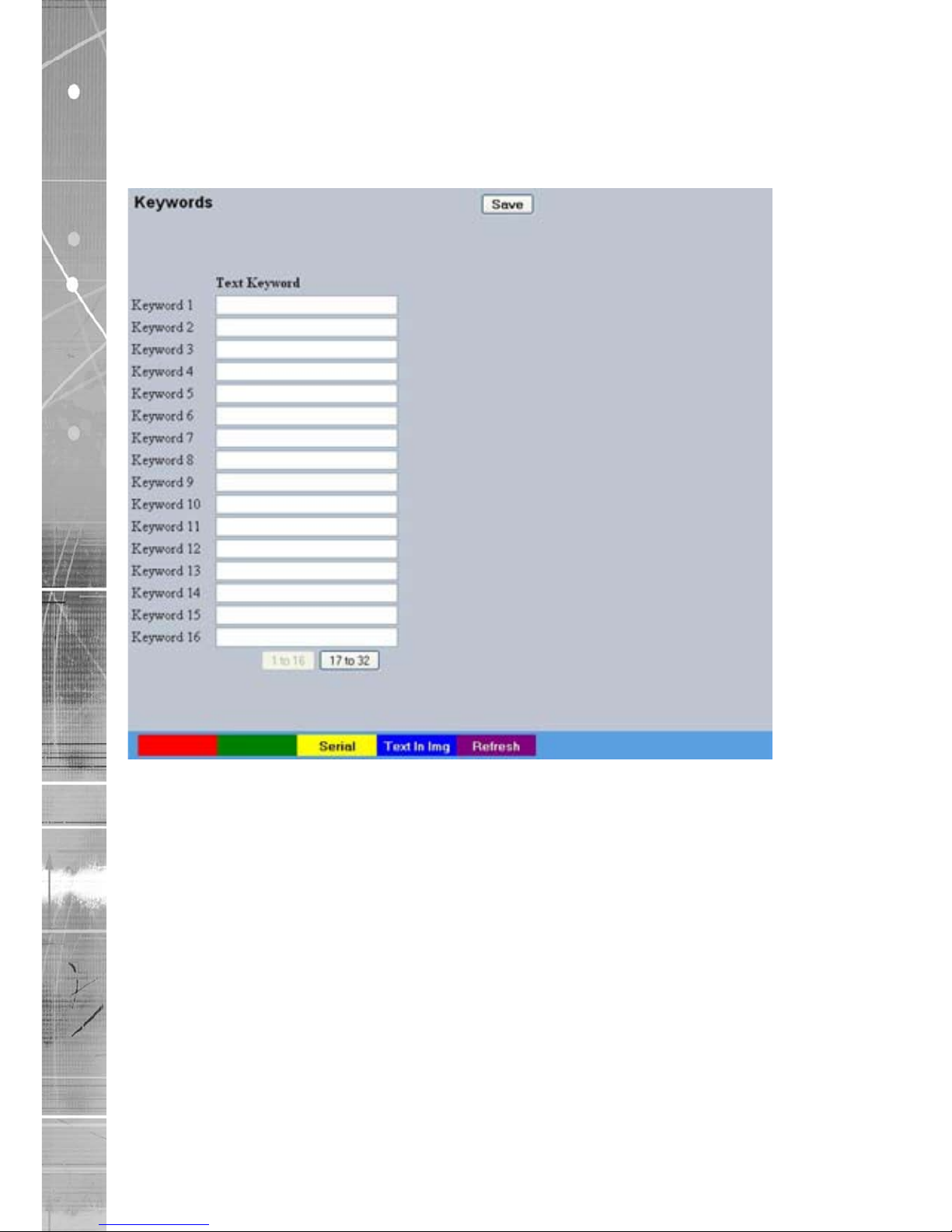
Dedicated Micros ©2009
96
SD Advanced
Keyword
This menu allows specic keywords received via the text stream to be congured and enabled as
event triggers. The ‘Enable Keywords’ function need to be activated in the ‘Text in Image’ menu for
this feature to operate.
Text Keyword The unit can be congured to react to dened keywords appearing
in text data and treat them as alarm zone inputs. In turn this
generates events in the event database. The advantage of this
feature is that it allows the user to see exactly which keyword
triggered an alarm. A total of 32 Keywords can be congured and
each can be up to 20 characters in length. All of the keywords will
be active on the selected Zone keyword channel, refer to “Zone
Input -> Input”.
Note:
Increasing the number of keywords can signicantly increase the number of stored events.
Note: Refer to ‘Text In Image’ and ‘Serial Ports’ for further guidance on integrating text data.
Page 97
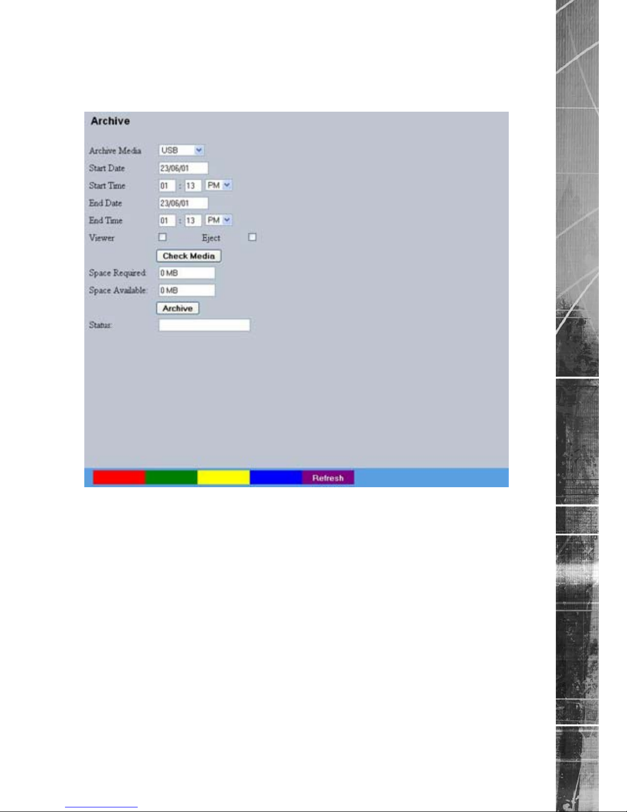
Dedicated Micros ©2009
97
SD Advanced
Archive
This menu allows Event database information to be downloaded to an inserted DVD/CD or
connected USB media device.
Archive Media Select to archive to either a DVD/CD or USB media device.
Start Date Enter a start date for the event download.
Start Time Enter a start time for the event download.
End Date Enter an end date for the event download.
End Time Enter an end time for the event download.
Viewer When selected, the unit will add a Viewer program to the archive.
It is recommended that this option be selected as it will ensure the
downloaded video images can always be successfully viewed.
Check Media button Selecting this option will display the space required (in
megabytes) for the chosen event period to be fully downloaded.
The space currently available on the CD/DVD or USB device is
also shown.
Archive Space Required Space required for archive download.
Archive Space Available Space currently available on CD/DVD or USB device.
Archive button Select this button to begin the Archive process.
Status During Archiving, status messages will be displayed detailing the
archive process.
Page 98

Dedicated Micros ©2009
98
SD Advanced
Oracle Dome Conguration
If a camera channel has a Dedicated Micros Oracle dome camera connected, the Oracle
Conguration menus can be used to view settings and establish Presets, Patrols and Privacy
Masks. Refer to individual menus for further details.
The Status page details fundamental information regarding the status of the Oracle Dome i.e. the
model type and the version of software/rmware installed.
The Presets page allows Preset positions to be congured and stored.
The Sectors page enables the cameras 360 degree eld of view to be effectively split into 32
segments. These segments can be named and displayed via the On Screen Display (OSD
Advanced).
The Patrols page allows camera patrol sequences to be established and congured. The Patrol
feature uses established preset positions to automatically pan, tilt and zoom the camera in the
selected sequence.
The Privacy Masks page allows privacy masking to be established and congured. The Privacy
Mask feature can be used to ‘blank out’ sensitive or private areas which appear in the cameras eld
of view.
The OSD Advanced Settings page allows the Oracle Dome OSD Advanced (On Screen Display)
information to be congured. This text will accompany displayed camera images in the Viewer
menus.
The Camera Settings page enables features such as white balance and shutter speed to be
congured.
The Event Settings page allows actions to be established and congured for the Oracle Dome
camera following an alarm. A Home position can be established and the delay time set for what
period of inactivity is required before the camera will be sent to its home position.
Page 99
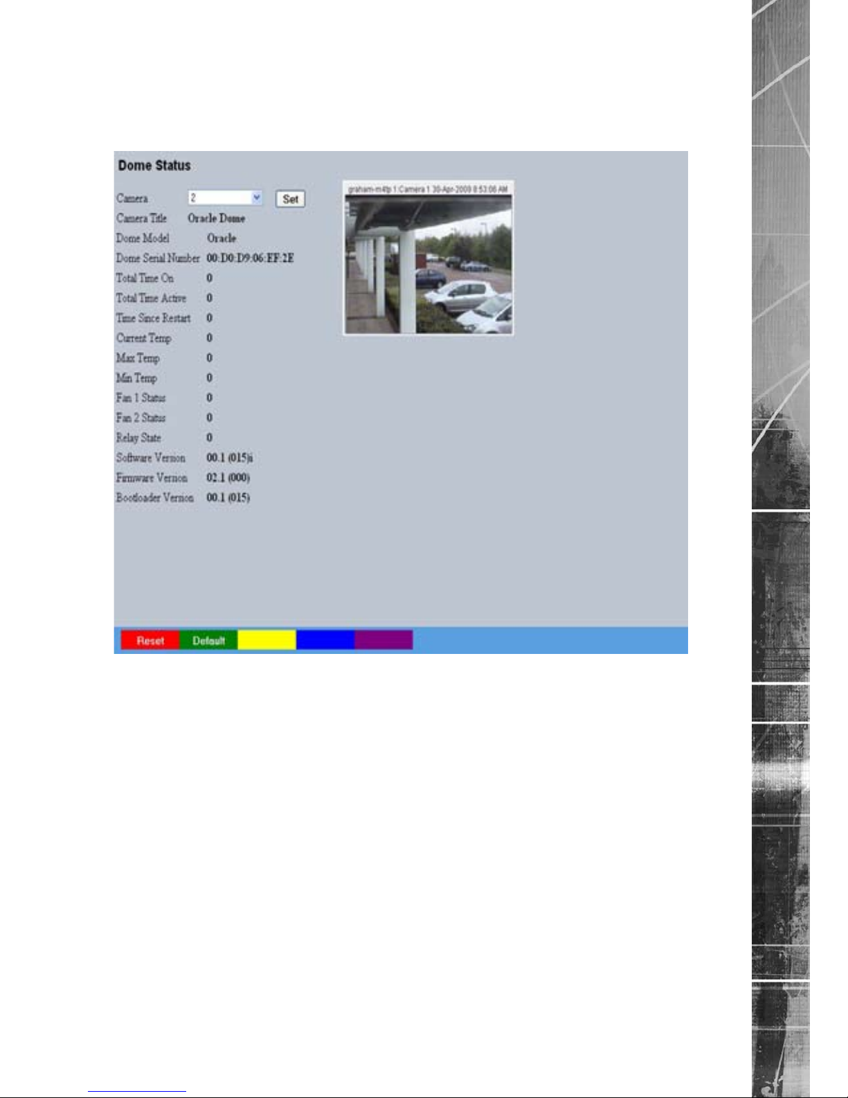
Dedicated Micros ©2009
99
SD Advanced
Status
This menu details information regarding the status of the Oracle Dome, notably the model type,
current temperature and the version of software/rmware installed.
Camera Select a camera channel. The menu will only display successfully
if the chosen camera channel has an Oracle Dome camera
connected.
IMPORTANT: All subsequent Oracle Conguration menus will relate to the camera selected
here. Camera selection is only possible via this Status menu.
Camera Title Title assigned to the selected camera channel.
Dome Model Details the product model.
Dome Serial Number Identies the serial number of the specic camera.
Total Time On Details the operational life time of the camera to date.
Total Time Active Details the total time the unit has been active (in motion).
Time Since Restart Details the time since the camera was last reset.
Current Temp Details the current temperature of the camera unit.
Max Temp Details the maximum temperature the camera unit has reached.
Min Temp Details the minimum temperature the camera unit has reached.
Fan 1 Status Details the operational status of installed Fan 1.
Fan 2 Status Details the operational status of installed Fan 2.
Relay State Details the operational status of the camera unit’s relay.
Page 100

Dedicated Micros ©2009
100
SD Advanced
Software Version This identies the version of software the camera unit is running.
Firmware Version This identies the version of rmware the camera unit is running.
Bootloader Version This identies the bootloader version of the camera unit
is running.
 Loading...