

Page 1
1
Pick-a-Point
User Guide
Page 2

2
Table of Contents
Overview 3
Notes for User 3
Workstation CPU Screen Layout
4
Menu Bar 4
Map Window 5
Multi-Screens 7
Start/Stop Sequence 8
Set Time/Date
8
DVR Search and Playback 9
Download / Copy Video 1
0
Event List 1
2
Observed Events 13
Logging an event 1
3
Replaying an event 1
3
Site List 1
4
Description 1
4
Manager Menus 1
5
Setting up Sequences 1
7
Basic Configuration 1
8
Connections at the rear of the unit 1
8
Packing List 19
Logging on 19
Page 3
3
Overview
Pick-a-Point is a dedicated IP keyboard solution
with joystick control that is designed to replicate the
traditional analogue matrix, offering digital reliability
and retrieval speed. Integration with existing analogue
systems is seamless, giving the station control over all
servers, domes, DVR’s and cameras.
It can operate as an additional control point on an
existing Pick-a-Point system, or work standalone to
provide composite viewing and control of any Dedicated
Micros NetVu Connected Server, DVR or IP Camera.
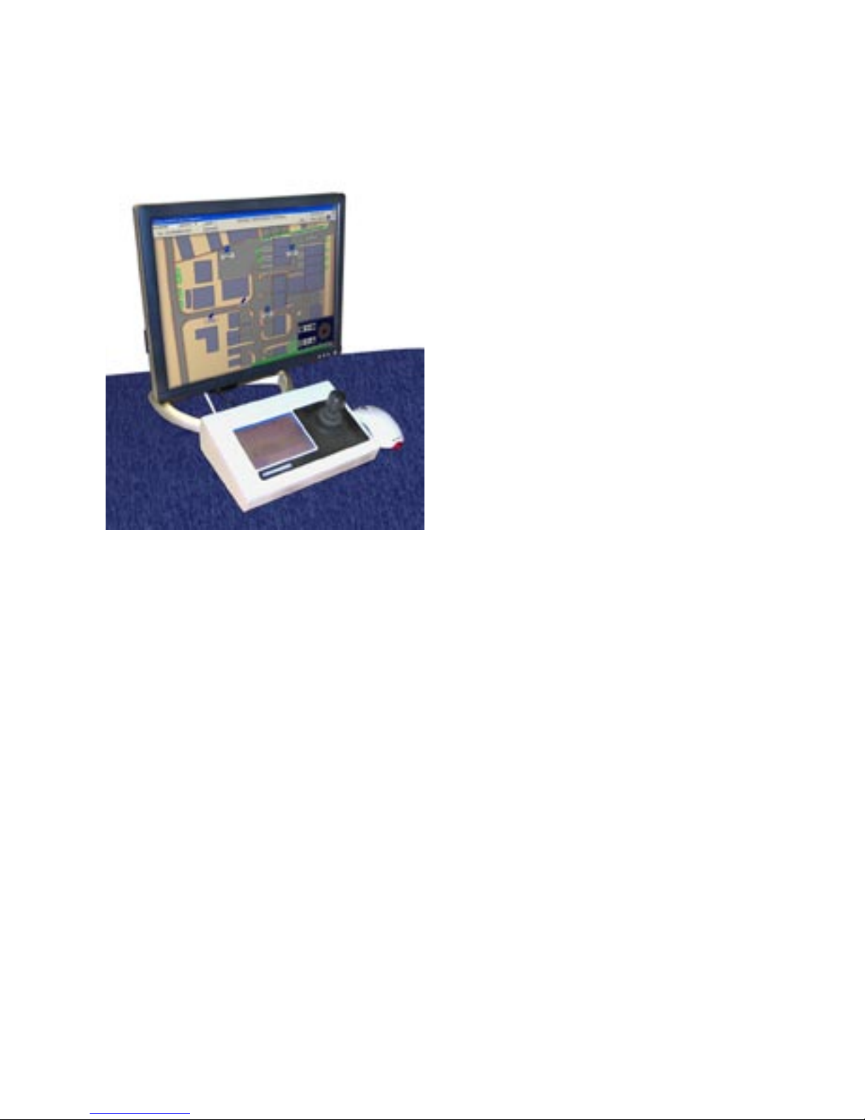
The keyboard and joystick control offer a familiar
environment for operators, eliminating the retraining
requirement associated with PC based systems. The
integrated touch screen keyboard provides intuitive
camera selection and joystick telemetry control,
removing the need for a QWERTY keyboard.
The powerful graphical user interface allows quick
navigation of the menus and access to sites. Operators
can simply pick and click cameras to view the required
images. The bespoke system, with customer specific
maps installed, is designed as a turnkey solution to
meet the exact operational requirements.
The system is configured and commissioned on site by a Dedicated Micros technician or appointed individual.
Custom maps are added to suit the users requirements, offering a graphical representation of the sites being
monitored. Camera icons and hotspots included in the map aid the operators, by simplifying camera selection
and system navigation.
Combined with Dedicated Micros’ world leading NetVu Connected technology, the Pick-a-Point system offers a
powerful networked monitoring solution.
More information is available from the Dedicated Micros Website.
Go to
www.dedicatedmicros.co.uk
Notes for User
• Cameras can be selected directly from the map or by selecting the camera number from the Matrix
keyboard.
• The Pick-a-Point system can handle any number of cameras and monitors. Connection is limited by the
practical capability of a single operator to monitor all the connected sites.
• Hover over the camera on the map to see the IP address of the Server.
• Multiscreen option will give a Quad screen display.
• There is built in support for the listed Mouse and CD writer. Before connecting an alternative, please
contact Dedicated Micros’ Technical Service department for advice.
Page 4
4
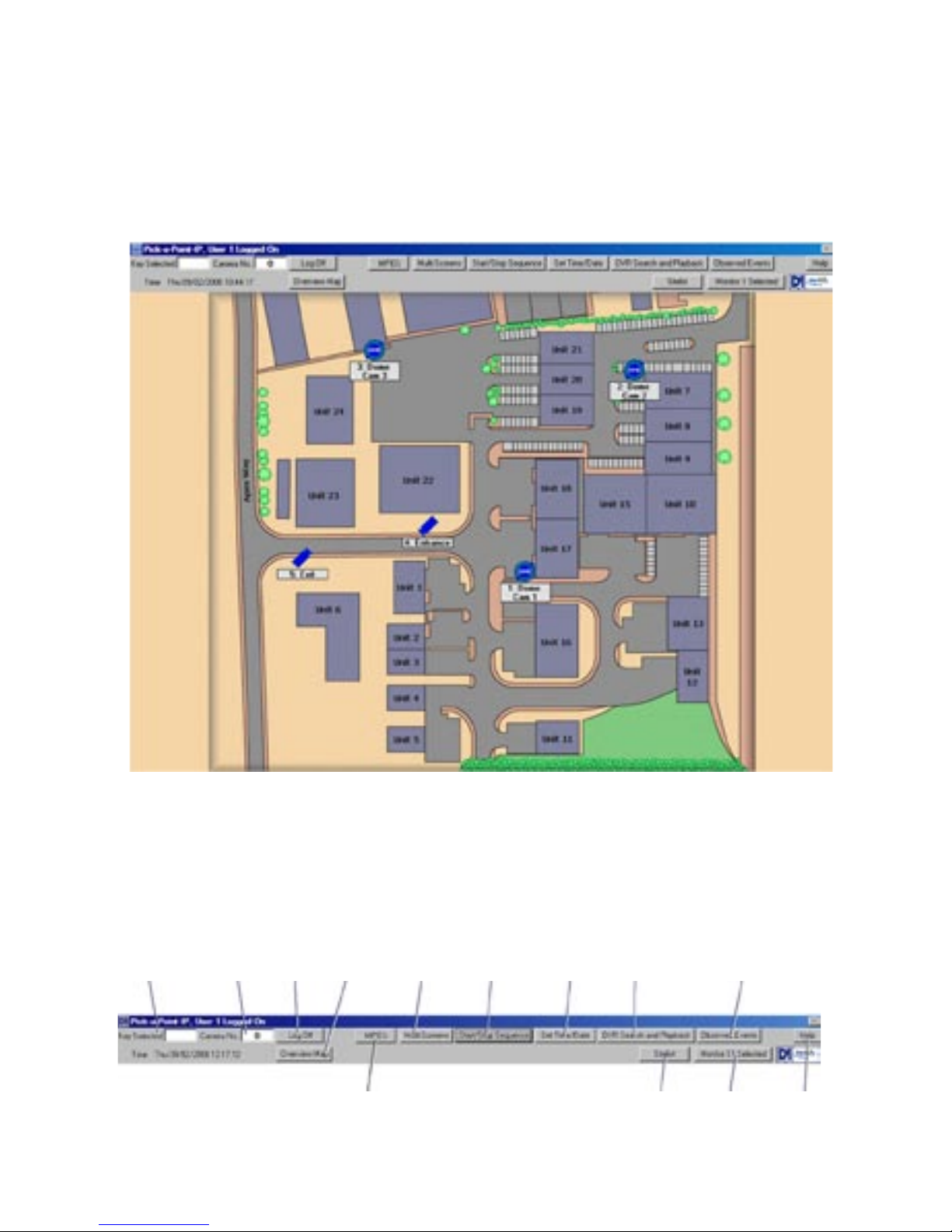
Workstation CPU Screen Layout
The workstation screen is divided into two sections pictured below.
The menu bar is displayed across the top of the screen, with the map window below.
Menu Bar
The menu bar at the top of the screen allows access to the available menus. These will change according to
the log in used. The menu bar, shown below, is what a user will have available. A description of each button
function is listed below.
Menu Bar
1 2 3 4 5 6 7 8 9
10 11 12 13
Page 5
5
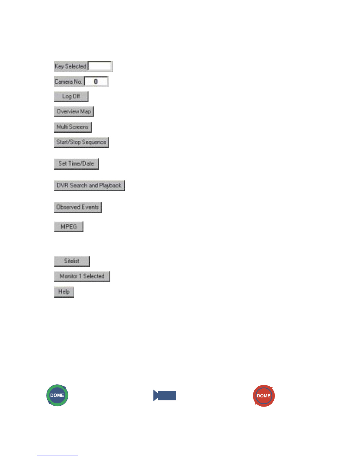
User Button Functions
1
Displays the key number selection from the keypad.
2 Displays the currently selected system camera number.
3 Opens the ‘Log Off’ system window (see Logging On and Off).
4 Returns the display to the top level map.
5 Opens the ‘Multi Screen’ window (see Multi-Screens).
6 Starts or stops a sequence on the currently selected monitor (see
Sequences).
7 Allows the operator to set the workstation time and date (see Setting The
Time And Date)
.
8 Opens the DVR search and playback window (see DVR Search /
Playback).
9 Logs / recalls a time, date and camera number when a suspicious event
occurred (see Observed Events).
10 If an MPEG-4 or MJPEG video source has been selected, there will be an
option to dynamically switch the view between JPEG and MPEG modes.
The button will display the alternative option. The current feed will be
shown on the monitor.
11
Displays a list of sites / map levels (see Site list).
12 Allows the monitor selection to be changed (see Changing monitors).
13 Displays program version information.
Map Window
The map window shows a plan for the site under observation. These maps have been loaded as part of the
initial configuration process by the integrator and give the operator information on the location of the cameras,
to enable efficient and quick tracking and operation.
The icons represent the different cameras that are linked to them. When a camera is selected onscreen, it
will be displayed on the monitor currently under control. Refer to the Tcommand Keyboard manual for more
information on selecting cameras and monitors.
Available icons
Dome Camera Camera Selected Camera
Page 6
6
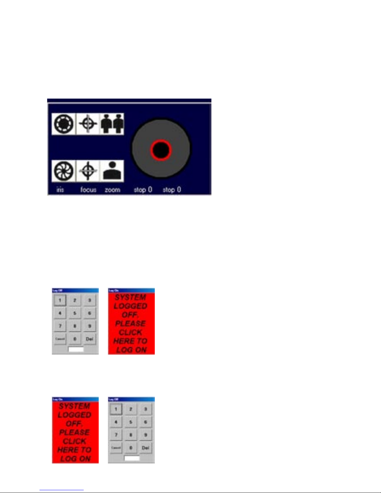
Backup Pick-a-Point keyboard
If the connection to the Pick-a-point keyboard is lost, an onscreen version (shown below) will automatically
appear. This can be dragged to any position on the monitor. It will disappear once the connection to the
keyboard has been re-established.
The on-screen keyboard offers telemetry control via the joystick on the right, and the ability to control zoom, iris
and focus.
Logging On and Off
To log off;
1) Touch or click on the ‘Log Off’ button on the menu bar. The Log Off window will appear.
2) Enter the four digit pin code (9999).
3) The ‘Logged Off’ window will be displayed.
To log on;
1) Touch or click on the red area and the ‘Log On’ button on the menu bar.
2) Enter the appropriate four digit PIN code.
Page 7
7
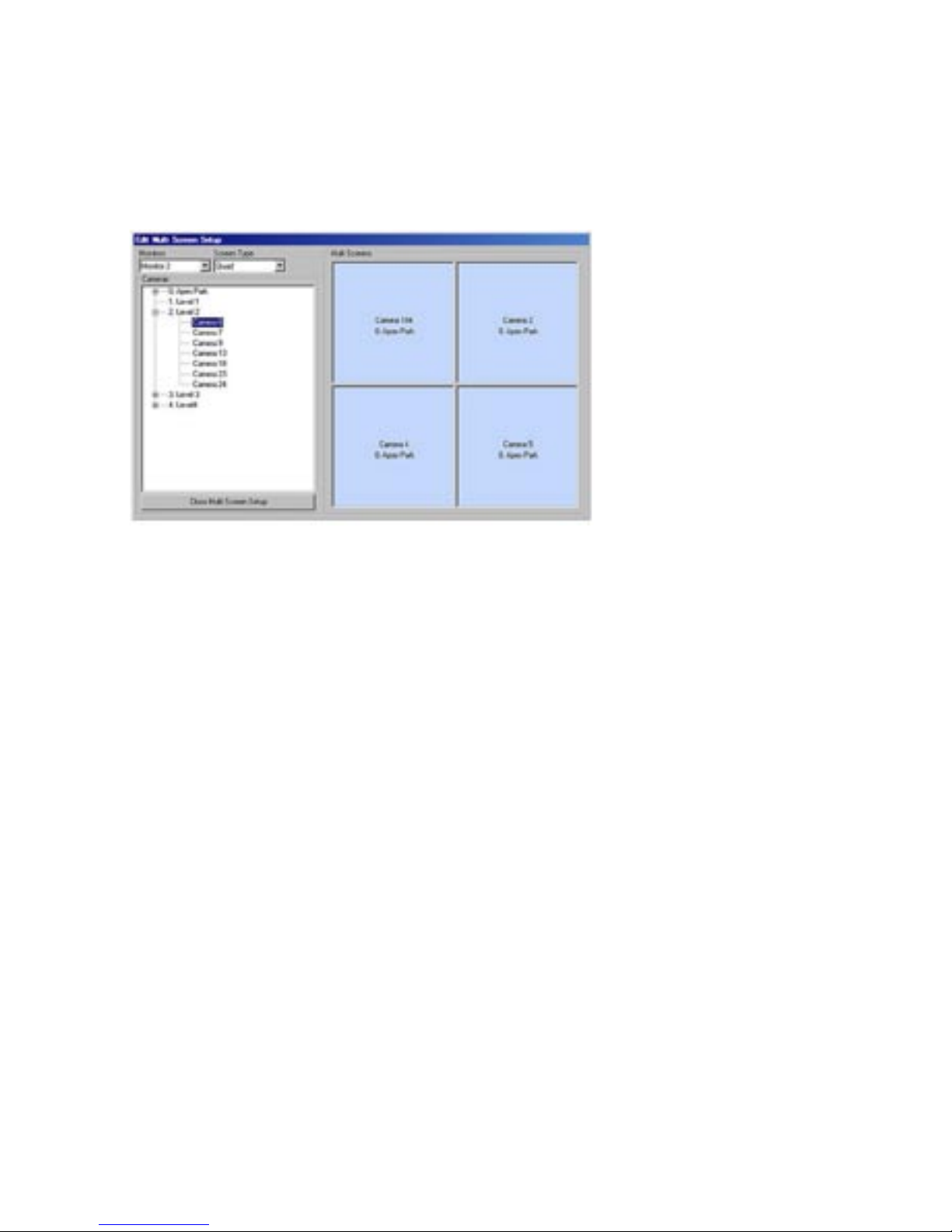
Multi-Screens
The ‘Multi Screens’ button allows the currently selected monitor to placed into a quad. This enables 4 images
to be displayed on a single monitor.
1) Use the ‘Monitors’ drop down menu to select which monitor will show the multi screen display.
2) Use the drop down menu under ‘Screen Type’
to select the display as quad (4 way) screen.
3) Cameras can now be dragged from the camera list into the viewing frames. Select a camera from the list
in the left window and ‘drag and drop’ into the appropriate frame.
This menu can also be used to assign a camera to a monitor in full screen mode.
1) Use the ‘Monitors’ drop down menu to select which monitor will show the full screen display.
2) Use the drop down menu under ‘Screen Type’
to select the display as Full Screen.
3) Cameras can now be dragged from the camera list into the viewing frame.
Page 8

8
Start/Stop Sequence
To start a sequence;
1) Select the required monitor (see Changing monitors).
2) Touch or click the ‘Start / Stop Sequence’ button.
The button for the monitor being sequenced will display an ‘S’ next to the monitor number.
3) Touch or click the button again to stop the sequence.
Set Time/Date
To adjust the workstation time and date, click or touch the ‘Set Time / Date’ button on the menu bar. The
window shown below will be displayed.
1) Click on or touch the plus and minus symbols next to the hours, minutes or seconds to adjust the time.
Click ‘Update Time’ to save the changes.
2) Click on the drop down menu next to the date to display the calender. Select the correct date and close
the window. Click ‘Update Date’ to save the changes.
3) Click or touch
‘Close’ to close the window.
Page 9
9
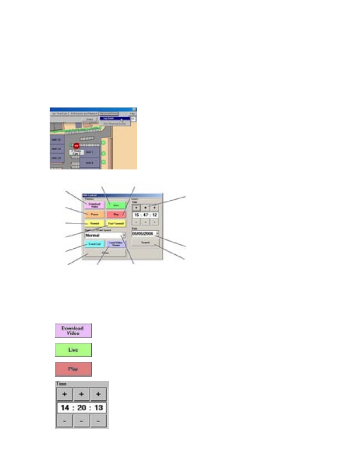
DVR Search and Playback
This facility is only available when logged in as a supervisor.
To review and download recorded images;
1) Touch or click the camera required for review
2) Touch or click on the ‘DVR search / playback’ button.
The DVR Control window will pop up.
This window will allow an operator to review recorded images from the selected camera, based upon
the time of recording. These can be fast forwarded and fast rewound on screen for easy access.
Use the Time and Date buttons in the right hand window to set the search parameters.
DVR Control
1
Opens the Download / Copy video window (See Download/Copy Video).
2
Switches the camera from playback to live mode.
3
Resumes playback from the time and date entered in the search section.
4
Selects the time of the recorded images for review.
1
13
12
11
10
8
7
6
5
4
32
9
Page 10

10
5 Selects the required recording date for review
6
Begins playback from the selected time and date.
7
Drop down menu sets the playback speed.
8
Launches the playback utility from the DVD after successfully downloading
an incident and writing it to a DVD.
9
Closes the DVR Control window.
10 Event List button opens the list of Events recorded by the DVR. (See Event
List below).
11
Fast forward the playback (Also possible using joystick pan right)
12
Rewind the playback (Also possible using joystick pan left).
13
Pauses the playback.
Download / Copy Video
1
2
3
4
5
6
7
8
9
10
11
Page 11

11
Description
1) Selects the video server (digital recorder) for
downloading recorded images.
2) Selects start and end times for the incident / event to be
downloaded.
3)
Selects start and end dates for the incident / event to be
downloaded
4) This should always be set to 0 during GMT and always
be set to 1 during BST otherwise the downloaded
footage will be wrong by 1 hour during British summer
time.
5) Selects the DVD recording device normally this will be
drive letter D:
6) Commences the video download and DVD writing.
7)
Cancels the current video download.
8) Closes the Download / Copy Video window.
Page 12

12
9)
Progress indication area. This shows the current state of
progress during the download / DVD writing.
Note: The time taken to download and write video to a DVD will vary considerably depending on the type of
network and required duration of the downloaded video.
10)
Download Selection. There are two download options.
Filtered PAR (No Audio): Filtered PAR downloads
are used when either the user only requires a short
amount of footage with no audio from a specific number
of cameras, or the network bandwidth on the system is
limited e.g. 512Kbps ADSL. Filtered PAR download are
considerably smaller then RAW downloads. Cameras
are selected on the DVR Camera Inputs panel.
RAW PAR (Audio, All Cameras): RAW PAR downloads
will download the video and audio from all cameras for
the specified time period.
11)
DVR Camera Inputs. Selecting filtered downloads allow
the user to select individual cameras via this panel.
Page 13

13
Event List
Press the Event list button to open the list of Events stored on the servers connected to the Pick-a-Point
workstation. To playback recorded images from the Event;
1) Select the Server
2) Select the start time and date. A list of Events will be displayed on the right hand side of the panel.
Events logged include Camera loss, System restart and Alarms.
3) Select an event by clicking with the mouse. Images will be replayed on the monitor.
Page 14

14
Accepting Alarms
When an alarm is tripped, the alarm icon will turn red and the nominated User will receive a notification.
When the icon is clicked, a dialog box will appear giving the alarm details.
Highlight the entry in the alarm box to accept the alarm and clear it.
Page 15
15
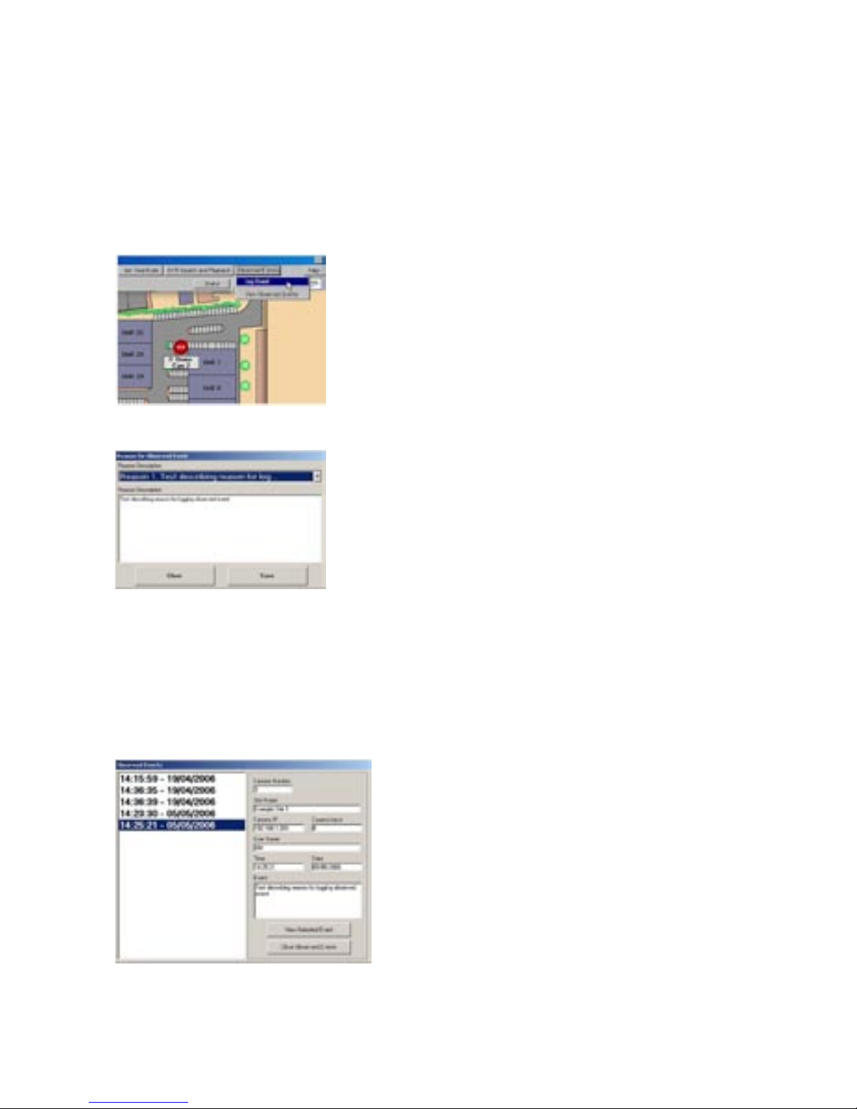
Observed Events
The observed events button, allows the operator to quickly and efficiently log a suspicious event or incident.
When the event is logged, the current time and date along with the camera number are logged into a database.
Logging an event
1) Click on ‘Observed Events->Log Event’ to add an event to the log.
There is a list of four pre-configured options to log against the event, plus a fifth, user defined option.
Select a suitable classification for the event.
Note: The user defined option can be entered by using the qwerty keyboard (if available), or by using the
onscreen keyboard that appears when the user defined option is selected.
Replaying an event
This facility is only available when logged in as a supervisor.
1) Touch or click ‘Observed Events’ and select view observed events.
2) Select an Event in the window, then touch or click ‘View Selected Event’. The corresponding camera
will be automatically selected along with the time and date the event was logged.
3) Playback will commence on the currently selected monitor.
Page 16
16
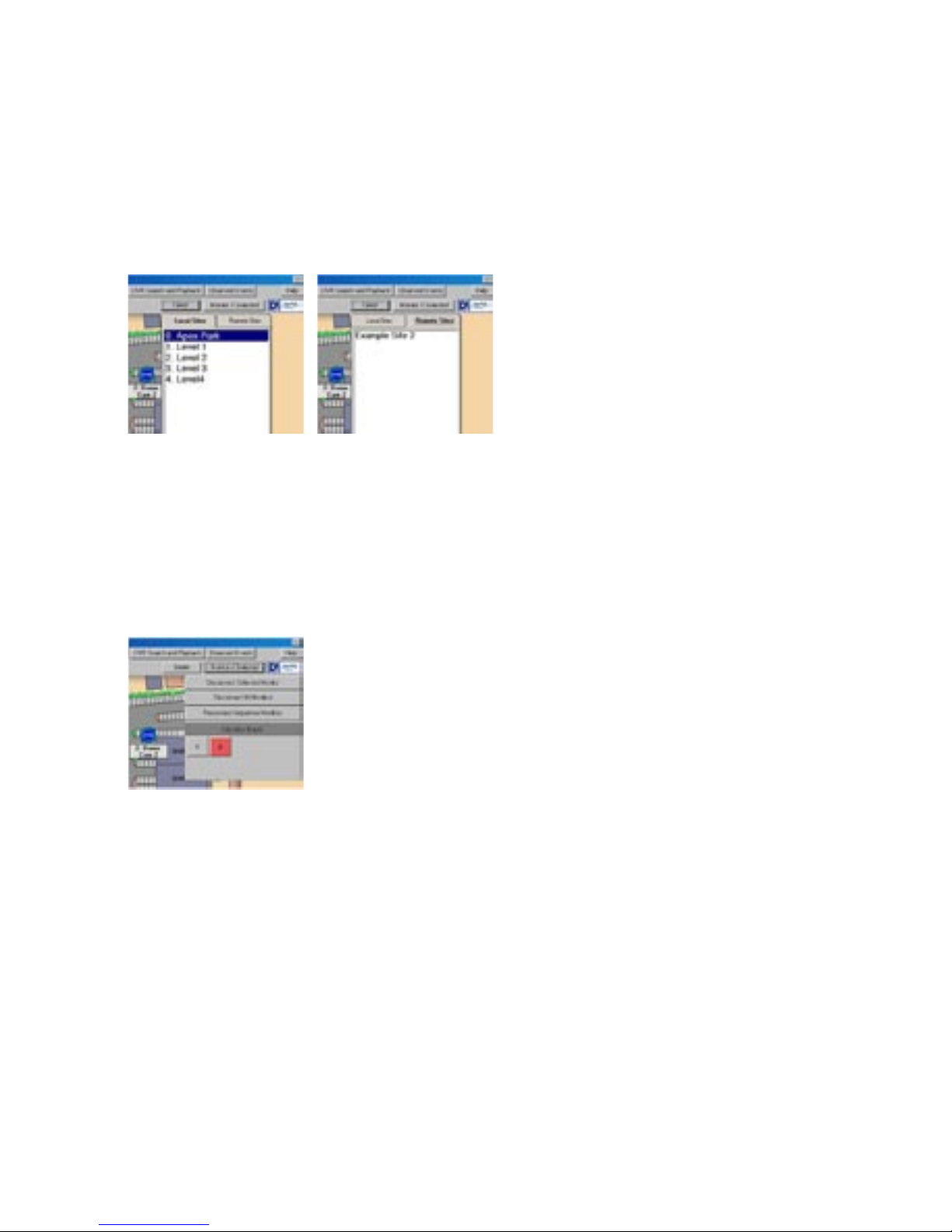
Site List
The site list window allows the operator to select different sites or site map levels. After selecting a site map
level, the displayed map will change and the camera icons will be shown on the map.
Local and Remote Sites
Remote sites can be selected from the ‘Site List’ button.
1) Click on ‘Sitelist’ to open the list of sites
2) Click on the tab labelled ‘Local Sites’ or ‘Remote Sites’.
2) Select the required site in the list to display it.
Note: The cameras on the remote sites cannot be selected from the touch screen keyboard. Also there are no
hotspots on the remote sites as they have no connection to each other, or to the local sites.
Changing Monitors
Description
Disconnect Selected Monitor. This button disconnects the currently selected monitor from the system.
This is used to reduce the bandwidth required by the system.
Disconnect All Monitors. Disconnects all monitors this would be used where 24 hour monitoring is
not required.
Reconnect Sequence monitors. Reconnect disconnected monitors and runs a pre-programmed sequence
on the monitors (when enabled).
Page 17
17
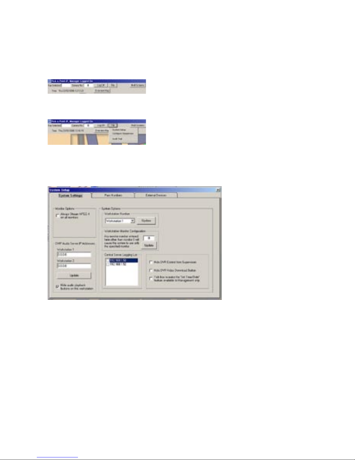
Manager Menus
Logging in as a manager will give access to extra menu options.
The file menu allows a manager to set up the system, to configure sequences and view the audit trail.
This menu page set is also used to configure passcodes and assign permissions, and to allow the connection of
external devices.
To configure the System;
Click on ‘File->System Setup’. The following screen will be displayed.
The System Settings screen allows the following adjustments to be made.
Feature Description
Monitor Options. When checked, MPEG 4 will be streamed to all of the monitors all of
the time.
DVIP Audio Server IP Addresses Pick-a-Point can support audio recording on up to 2 DVIP servers for
concierge / door entry conversation recording. The IP addresses of
the audio recording DVIPs are entered into these boxes. The update
button updates the IP addresses into the database. The ‘Hide Audio
Playback…’ checkbox will turn off the download audio button in the
Video download dialogue.
Central Server Logging List These are the IP addresses of the remote workstations which will
hold a copy of the audit trail database and can only be edited by an
appointed engineer.
Hide DVR control from supervisors When checked the DVR Control menu option will only be available to
managers.
Hide DVR Download button When checked the Download Video button in the DVR control window
will only be available to managers.
Tick Box to make Time and Date… The ‘Set Time/Date’ option in the menu bar will only be available when
a manager is logged on.
Page 18
18
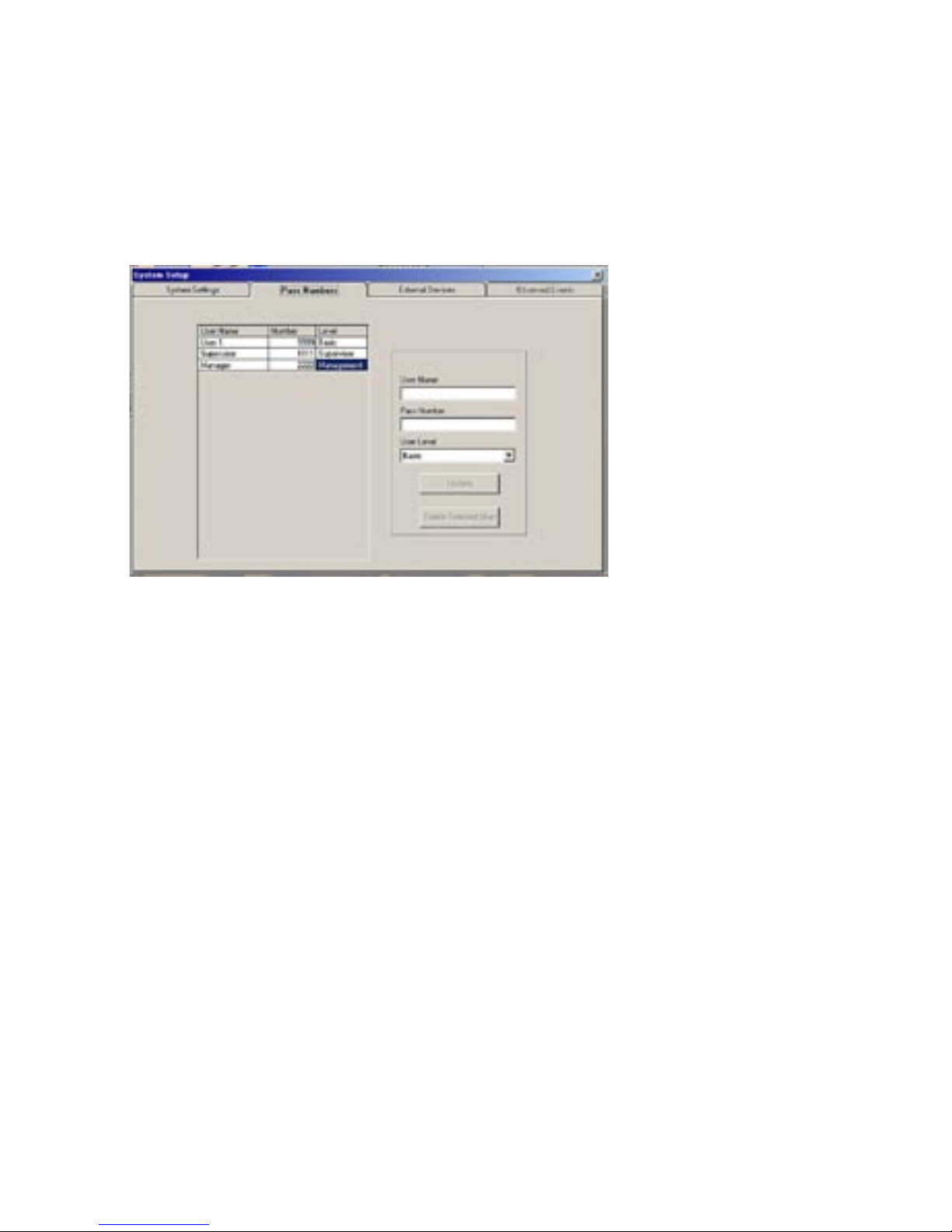
To Add or Remove Users;
The Pick-a-Point system automatically loads each users preferences on login.
Click on ‘File->System Setup’ and then click the tab ‘Pass Number’ at the top of the window to allow access
to new users and set authorisation levels.
The following screen will be displayed.
Assign a user name and a four digit pass code for the user. Use the drop down menu to select a level of
access. Use the Update button to add the new user.
This page can also be used to delete an expired user. Select the expired users name, then click on ‘Delete
Selected User’ to remove the user profile.
Page 19
19
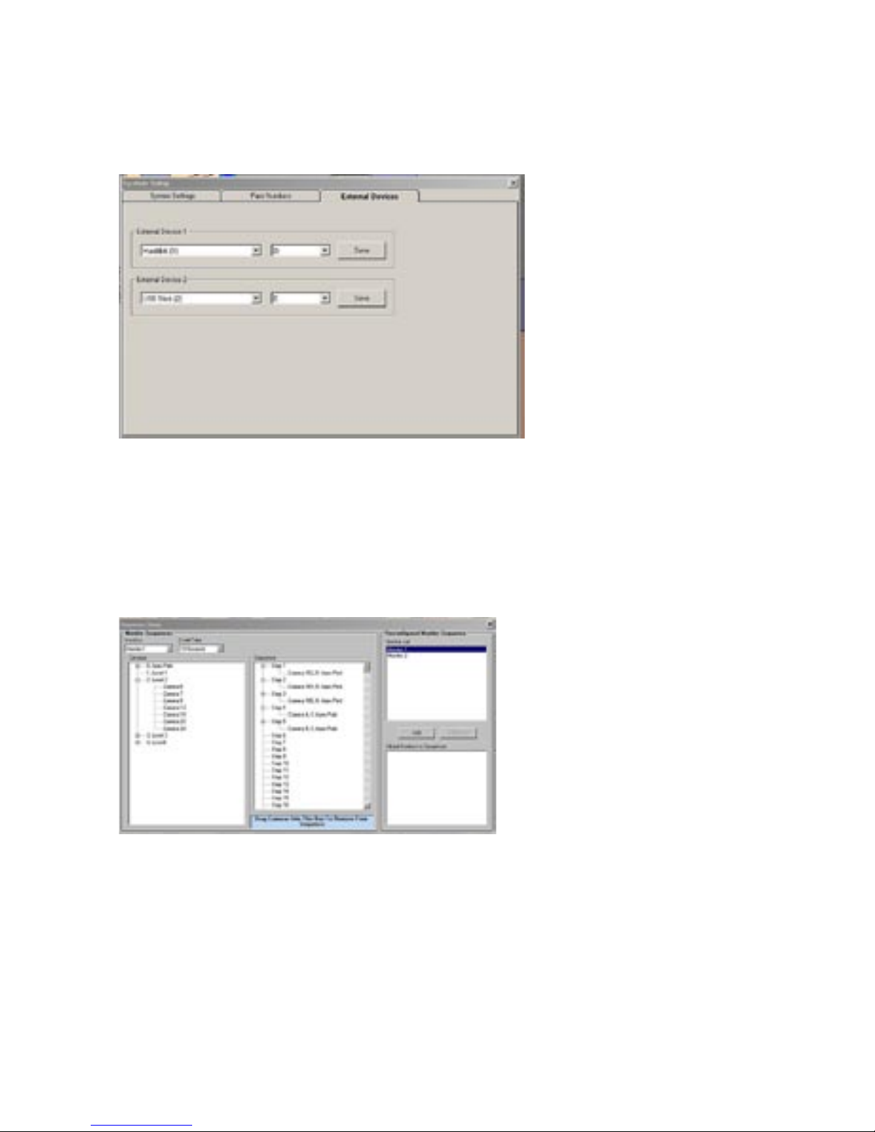
To add External Devices;
Click on ‘File->System Setup’ and then click the tab ‘External Devices’.
This menu allows a manager to add specific external devices to the system, along with an associated drive
letter. Devices include Hard Drives and USB sticks.
Setting up Sequences
Monitors can be arranged into a series of views which can then be observed by an operator. These are then
viewed by the operator using the ‘Start/Stop sequence’ command, using the appropriate monitor.
To set up a Sequence;
Click on ‘File->Configure Sequences’. The following screen will be displayed.
Select the Monitor will Display the sequence from the drop down menu at the top left of the page.
Select the dwell time (the length of time each image will stay on screen) using the drop down menu adjacent to
the Monitor select.
Available cameras are displayed in the left hand pane. These can then be dragged and dropped into the centre
pane to create a sequence.
Cameras can be removed from a sequence by dragging from the centre pane and dropping into the blue
window at the bottom of the page.
Monitor Sequences can be dragged from the ‘Monitor List’ into the ‘Global Monitors to Sequence’ window to
create a new list of monitors to sequence. This is viewed by pressing ‘Reconnect Sequence Monitors’ button
(See Changing Monitors).
Page 20
20
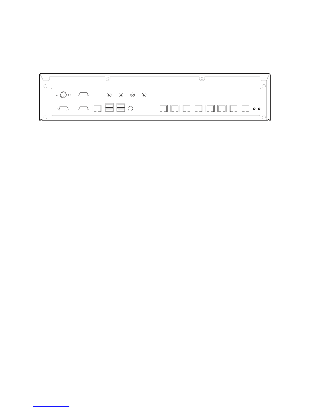
Basic Configuration
Connections at the rear of the unit
COM2
MIC LINE IN LINE OUT
HEAD
PHONES
SVGA
NET
KBD
USB USB
COM1
COM A COM B COM C COM D COM E COM F COM G COM H
Interface
SVGA SVGA Monitor Connection
KBD PS2 querty Keyboard - can be removed after configuration
Mouse Microsoft Wheel Mouse Optical 1.1A USB and PS/2 Compatible
Network and Communications
NET 10/100 / 10BASE-T / 100BASE-TX / 1000BASE-TX Network Port
USB 4 x USB 2.0 Ports
Mic 3.5mm jack socket for Microphone
Line In 3.5mm jack socket for Line In
Line Out 3.5mm jack socket for Line Out
Headphones 3.5mm jack socket for headphones
Data
COM Ports
COM1 & COM2 RS-232
COM A Pick-a-Point keyboard socket
COM B Serial Alarms connection
COM C - COM H Spare RS-232/RS-422 Ports
LED’s
Power LED adjacent to COM H Socket
Options
CD Writer Freecom Classic DVD+/-RW Double Layer USB 2.0
Touch Screen 3M Capacative
Page 21
21
Packing List
Box 1
Pick-a Point unit
Power supply for Pick-a-Point unit
Mains lead for UK/USA/Europe
PS2 querty keyboard
Optical USB mouse
Rack mounting ears for Pick-a-Point unit
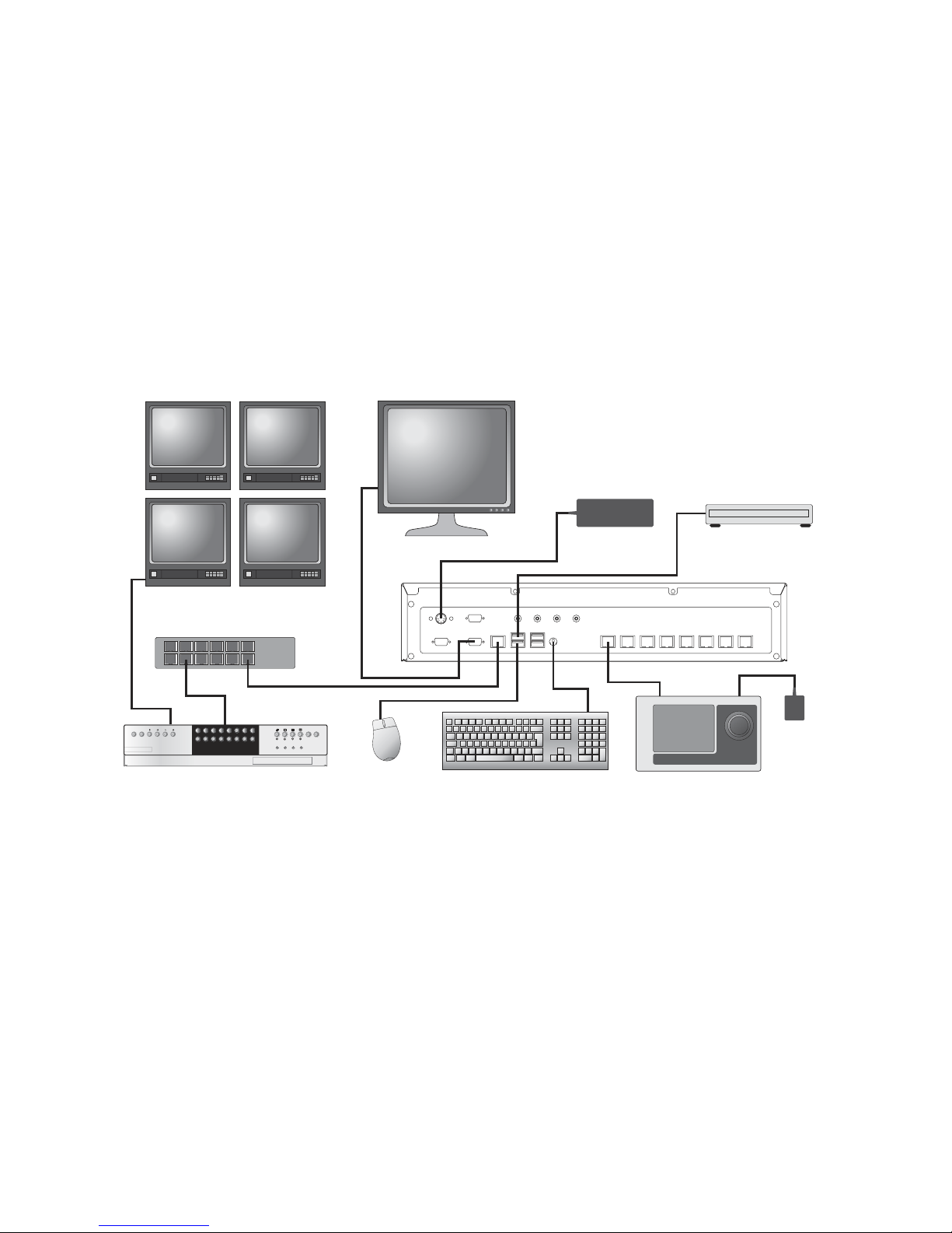
Sample Installation Diagram
COM2
MIC LINE IN LINE OUT
HEAD
PHONES
SVGA
NET
KB
D
USB USB
COM1
COM A COM B COM C COM D COM E COM F COM G COM
H
USB CD Writer
PC Monito
r
Powe
r
Supply
Powe
r
Supply
PS2 Keyboard - only
required for commissioning
Mous
e
Pick-a-Point
Keyboard
DV
R
Network switch
Monit
or Wall
Pick-a-Point
1 2 3 4 5 6 7 8
9 10 11 12 13 14 15 1
6
1 2 3 4 5 6 7 8
9 10 11 12 13 14 15 1
6
EVENT
GOT
O
COPY
MODE MENU
LIVE PLAY SPOT RECORD
Logging on
Note: Ensure all connections are made before powering the unit.
1 On power up the unit will automatically load the software application.
2 Log Off with the User password 9999.
3 Log in to the application using the provided Installer logon.
Box 2
Pick-a-Point Keyboard
Plug top power supply for T command keyboard (UK/US/Europe)
RS-485 keyboard cable (2m) RJ45 - RJ45
Breakout box - to increase keyboard range
Manual for Pick-a-Point keyboard
Page 22

22
Page 23

23
Page 24

24
Dedicated Micros Ltd.
11 Oak Street, Swinton,
Manchester.
M27 4FL,
United Kingdom
Tel: +44 (0) 161 727 3200
Fax: +44 (0) 161 727 3300
Dedicated Micros Europe
Neckarstraße 15,
41836 Hückelhoven,
Germany
Tel: +49 2433 5258-0
Fax: +49 2433 5258-10
DM France
9-13 rue du Moulinet
75013 Paris
France
Tel : +33 (0) 1 45 81 99 99
Fax : +33 (0) 1 45 81 99 89
Dedicated Micros USA.
14434 Albemarle Point Place,
Suite 100,
Chantilly, Virginia 20151 USA
Freephone: 800 864 7539
Tel: +1 703 904 7738
Fax: +1 703 904 7743
Dedicated Micros USA.
23456 Hawthorne Blvd. Suite 100,
Torrance, CA 90505,
USA
Tel: +1 310 791-8666
Fax: +1 310 791-9877
Dedicated Micros Australia PTY.
5/3 Packard Avenue, Castle Hill,
NSW 2154
Australia
Tel: +612 9634 4211
Fax: +612 9634 4811
Dedicated Micros Asia PTY
16 New Industrial Road,
#03-03 Hudson Techno Centre,
Singapore 536204
Tel: +65 62858982
Fax: +65 62858646
Dedicated Micros Middle East
Building 12, Suite 302,
P.O. Box 500291,
Dubai Internet City,
Dubai, United Arab Emirates.
Tel: +971 (4) 390 1015
Fax: +971 (4) 390 8655
Dedicated Micros (Malta) Ltd.
UB2 San Gwann Industrial Estate,
San Gwann
SGN 09 Malta
Tel: +356 21483 673
Fax: +356 21449 170
www.dedicatedmicros.com
MI-U-PPW01/E1-1
 Loading...