

Page 1

MSU
ManagedStorageUnit
SetupandMaintenanceGuide
Page 2

Dedicated Micros ©2008
2
MSU
Whilst every attempt is made to ensure these manuals are accurate and current, Dedicated Micros reserve the right to
alter or modify the specication of the machine described herein without prejudice.
Contents
Dedicated Micros MSU (Managed Storage Unit) .......3
Installing the MSU ......................................................4
Maintaining the MSU .................................................5
Notes .........................................................................8
Page 3

Dedicated Micros ©2008
3
MSU
DedicatedMicrosMSU
(ManagedStorageUnit)
The MSU (Managed Storage Unit) has an array of ve Hard Disk Drives mounted in a lockable
drawer in a neatly styled unit. There are dedicated fans for each disk to provide the optimal, stable
operating environment to prolong disk life. Constant monitoring of disk SMART parameters will
enable warnings of potential problems; therefore allowing maintenance to be scheduled to prevent
potential disk failure.
The disks and fans are all eld servicable. This manual details the servicing operation.
The MSU is available in the following sizes;
• 5.0 TB MSU (5*1000 GB drives)
• 3.75 TB MSU (5*750 GB drives)
• 2.5 TB MSU (5*500 GB drives)
• 1.25 TB MSU (5*250 GB drives)
Page 4
Dedicated Micros ©2008
4
MSU
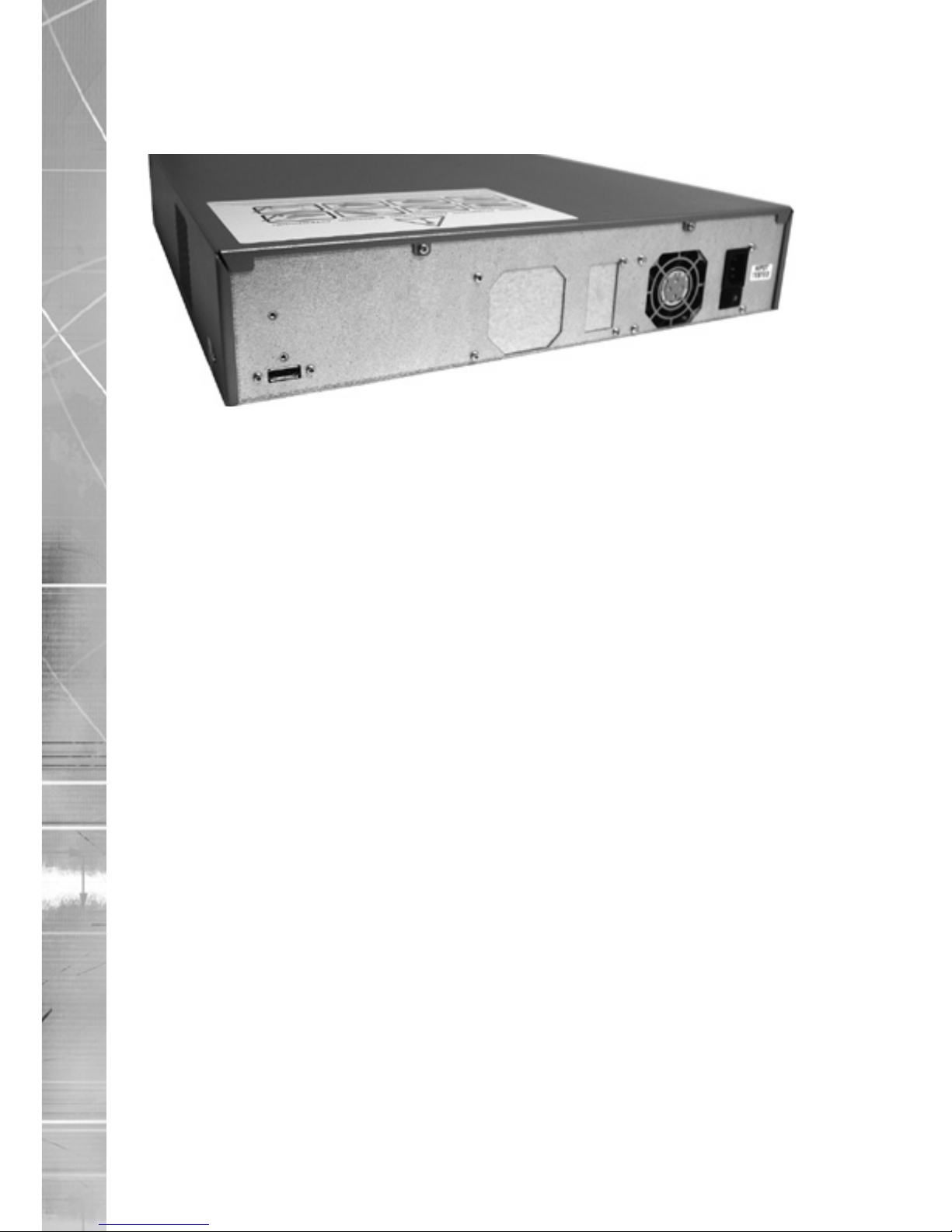
InstallingtheMSU
The MSU requires two connections.
1) Use the enclosed cable to connect between SATA sockets on the rear of the DVR
and the MSU. If using a different cable to that supplied, it is recomended that it be
no longer than one metre.
2) The MSU has an internal power supply unit. Connect the mains lead to the unit and
then to the wall socket, or to a fused spur connection. To be compliant with wiring
regulations in some countries; an Alarm/Security device should be connected to a
fused spur and not a wall outlet socket (check local regulations before installation).).
Installing The Cong File on the DVR
1) To successfully link the MSU to the DVR, the MSU Cong le must be installed
on the DVR. The Cong le can be located on the MSU Conguration CD which
accompanies the unit.
Either:
Insert the CD containing the cong le (vidcfg.ini) into the CD drive of the DVR and
select the software upgrade option via the DVR’s Conguration menus.
Or:
Extract the the vidcfg.ini le and copy into the /etc directory of the DVR via FTP
(File Transfer Protocol) client software i.e. Core FTP.
2) Reboot the DVR.
IMPORTANT: To successfully install the cong le, the DVR may require a software upgrade.
Please ensure the software versions (or higher) listed below are installed:
SD Range Application 4.2 (20.14)
DV-IP Server 4.3 (22.0)
DV-IP RT 4.3 (22.0)
DV-IP HD 4.3 (22.0)
Note: DVR software upgrades can be downloaded via the Dedicated Micros website
(dedicatedmicros.com).
Front Panel Display
The front panel displays the following LEDs.
Power: Indicated power is connected to the MSU.
Link: Indicates SATA link is active.
Alarm: Warns of internal faults detected by the unit.
Ofine: For Future Use.
Page 5

Dedicated Micros ©2008
5
MSU
MaintainingtheMSU
Opening the MSU
1)
2) Lower the front ap on the MSU.
3) Use the provided key to unlock the Draw.
Open the hinged front left ap and release
the transportation screw.
Page 6

Dedicated Micros ©2008
6
MSU
43) Pull the drawer open.
5) The drawer is mounted on two sliding runners. These runners have a securing
catch which needs to be released before the drawer will close.
Page 7

Dedicated Micros ©2008
7
MSU
Replacing a Hard Drive
Procedure
1) Follow the steps detailed in the section ‘Opening the MSU’
2) Identify the hard drive to be removed. Each hard Drive is secured by four screws.
Remove the screws and lift the hard drive up. Retain the screws.
3) The SATA and power connection are incorporated into one plug. Remove the plug
from the back of the drive.
4) Replace the hard drive with a replacement unit from Dedicated Micros. Secure the
hard drive using the previously removed screws.
Note: Remember the catch on the drawer slider needs to be unlatched to allow the drawer to
close properly.
Page 8

Dedicated Micros ©2008
8
MSU
Technical Specication
PART NUMBER MSUA1T25 MSUA2T5 MSUA3T75 MSUA5T0
STORAGE
(UNFORMATTED) 1.25TB 2.5TB 3.75TB 5.0TB
FORMAT 5 x 250GB HDD 5 x 500GB HDD 5 x 750GB HDD 5 x 1.0TB HDD
DVR INTERFACE SATA
ENVIRONMENTAL
CONTROL Intelligent individual disk cooling
POwER SUPPLy 1 x 200W Internal
HEALTH
MONITORING Continuous (Disk and Cooling fans)
MAINTENANCE Field maintainable HDD and fans with front panel access
AC INPUT
VOLTAGE 120v (60HZ) / 240v (50HZ): Selectable
OPERATING
TEMPERATURE 5°C-45°C
OPERATING
HUMIDITy 5%-85% Non-Condensing
CONFIGURATION 2U Rack Mount
DIMENSION (MM) 89mm (H) x 440mm (W) x 537mm (D)
wEIGHT 16.65kg
Page 9

Dedicated Micros ©2008
9
MSU
Notes
Page 10

Dedicated Micros ©2008
10
MSU
Notes
Page 11

Dedicated Micros ©2008
11
MSU
Page 12

Dedicated Micros Europe
Neckarstrae 15,
41836 Hückelhoven, Germany
Dedicated Micros France
9-13 rue du Moulinet
75013 Paris, France
Dedicated Micros Slovenia
Delavska cesta 26,
4208 Sencure, Slovenia
Dedicated Micros Benelux
Joseph Chantraineplantsoen 1,
3070 Kortenberg, Belgium
Dedicated Micros USA.
14434 Albemarle Point Place, Suite 100,
Chantilly, Virginia 20151 USA
Dedicated Micros USA.
23456 Hawthorne Blvd.
Suite 100, Torrance,
CA 90505, USA
Dedicated Micros, Australia PTY.
5/3 Packard Avenue, Castle Hill,
NSW 2154, Australia
Dedicated Micros, Asia PTY
16 New Industrial Road,
#03-03 Hudson Techno Centre,
Singapore 536204
Dedicated Micros Middle East
Building 12, Suite 302, P.O. Box 500291, Dubai Internet
City, Dubai, United Arab Emirates
Dedicated Micros (Malta) Ltd.
BLB017, Bulebel Industrial Estate,
Zejtun, ZTN3000, Malta
Dedicated Micros Ltd.
1200 Daresbury Park, Daresbury,
Cheshire, WA4 4HS, UK
Installed by
MI-I-MSU/E1-0
 Loading...