

Page 1
EcoSense
Installation and
Operation Guide
Page 2
EcoSense
Contents
Introduction ....................................................................................... 3
Features ........................................................................................... 4
Important Safeguards ....................................................................... 6
Installing the Unit .............................................................................. 8
Installation ...................................................................................... 10
Accessing & Conguring the Unit ................................................... 18
Remote Control .............................................................................. 20
Main Menu ...................................................................................... 24
Navigating The Conguration Menus ............................................. 26
System ........................................................................................... 27
Display Settings .............................................................................. 51
Camera Settings ............................................................................. 57
Intelligent PTZ ................................................................................ 62
Record Settings .............................................................................. 75
Schedule ........................................................................................ 85
Alarm Settings ......................................................................................90
Network Settings .......................................................................... 106
Text ............................................................................................... 120
Archive ......................................................................................... 124
Diagnostics ................................................................................... 126
Event Search ................................................................................ 128
Unit Operation .............................................................................. 130
Operating the Viewer .................................................................... 131
Using the optional Keyboards
(DM/KBC1 & DM/KBC2) ............................................................... 156
Appendix A .................................................................................. 160
Appendix B ................................................................................... 167
Appendix C ................................................................................... 168
Appendix D ................................................................................... 170
Appendix E .................................................................................. 171
Appendix F ................................................................................... 172
Appendix G - Multicast ................................................................. 174
Appendix H - Monitor Output ........................................................ 175
Notes ............................................................................................ 176
Whilst every attempt is made to ensure these manuals are accurate and current, Dedicated Micros reserve the right to alter or
2
modify the specication of the machine described herein without prejudice.
Dedicated Micros ©2011
Page 3

Introduction
What is the…
EcoSense ?
The EcoSense from Dedicated Micros provides low cost multi channel recording with simultaneous
playback and viewing; ideal for the cost conscious user who needs reliable, networked, high
performance CCTV at an affordable price.
Available with 4, 8 or 16 camera inputs, all offering telemetry control, the EcoSense has built in
Alarm functionality and onboard Activity detection software.
The state of the art touch sensitive front panel and the accompanying Infra-Red (IR) Remote Control
make for simple, quick operation. Dedicated Micros trademark plug and play intuitive set-up, userfriendly interface with colour coded ‘softkeys’ and conguration menus common to both local monitor
and web interface; help keep installation and operator training to a minimum.
The EcoSense offers a global record rate of up to 200pps (dependant on model) at CIF and can
record up to 16 cameras (dependant on model) simultaneously in MPEG-4 or JPEG format. The
Prole Record feature enables an operator to set different recording rates and resolutions across
scheduled, normal and alarm modes for all cameras.
As standard, the unit includes internal storage with a CD/DVD-R Writer* and USB ports for external
video archiving.
Among the many other features included as standard on the EcoSense are; multiway display,
multiple language support, audio recording, activity detection and remote monitoring using NetVu
ObserVer (utilising DM’s unique TransCoding capabilities to provide uent live and replay images).
The EcoSense is undoubtedly the ideal product when high-performance video recording and
transmission is required at an affordable cost.
For further information, please visit the website:
www.dedicatedmicros.com
or contact Dedicated Micros customer services in your region.
* Installed DVD writer only accepts -RW media.
EcoSense
Dedicated Micros ©2011
from Software version 6.3 (8.0071) M4TP
Webpage version wp81.1(5036)ns
3
Page 4
EcoSense
Features
• 4, 8 or 16 camera input options
• True global record rate of up to 200pps at CIF
• Simultaneous Live viewing and Recording
• D1/4CIF/2CIF/CIF record rate at 3/3/6/12pps per camera
• JPEG or MPEG-4 recording and transmission
• Touch sensitive front control panel
• Easy to use on-screen, colour coded softkeys
• Field serviceable hard drives
• Serial Telemetry support
• All DVR functions fully supported by Keyboard/IR Remote Control
• MultiMode Recording - Dynamically-switchable resolution, record-rate & compression
(MPEG4/JPEG) per camera
• Single, Picture in Picture and Multiway displays
• Live and playback viewing locally and over Ethernet
• Built in activity detection
• Built in DVD writer* and USB ports for download of video archive to external
ash memory
• Web pages provide easy remote conguration
• Alarm Inputs & Outputs
• Optional external keyboard available
* Not EcoSense 4
The unit has NetVu Connected technology built-in to ensure maximum compatibility with future
developments in networked security. NetVu Connected technology enables the Unit to fully interact
with other NetVu Connected compatible products from Dedicated Micros including the DV-IP
Decoder, NetVu ObserVer and PDA Viewers. Providing interoperability between the worlds leading
security companies, NetVu Connected uses industry standard networking protocols supported by a
wide range of third party integration products and SDKs to ensure future on-going compatibility.
COMMON CONFIGURATION INTERFACE
A Common Conguration interface is displayed when the unit’s conguration screens are accessed
locally at the unit or remotely via a web browser. This unied system ensures that the installer is
familiar with the conguration screens irrespective of their location to the unit, minimising training
and familiarisation time and increasing the speed of installation and alteration.
The Unit includes a unique colour-coded menu structure and onscreen Graphical User Interface
(GUI). Context sensitive, the menu structure always represents the area of the menu the user is in,
allowing them to quickly select the options and settings they need without having to trawl through
menu pages and options. The colour coded buttons displayed on the monitor match those on the
touch screen front panel and IR Remote Control, whilst control can also be conducted through an
attached USB Mouse or supported Keyboard (DM/KBC1 / DM/KBC2).
4
Dedicated Micros ©2011
Page 5

Design of the manual
The manual has three parts:
1. Installation Shows details of how to install the unit and connect external devices.
2. Conguration Shows details of the unit’s menus.
3. Operation Shows quick reference details on how to control the unit.
The order and layout of these pages has been designed to help the setup process. It is
recommended that the menus are edited sequentially (as they appear on the page), to enable
accurate, easy and efcient setup.
EcoSense
Dedicated Micros ©2011
5
Page 6
EcoSense
Important Safeguards
Read Instructions
All the safety and operating instructions should be read before the unit is operated.
Power Sources
This unit should be operated only from the type of power source indicated on the manufacturer’s
label.
Servicing
Do not attempt to service this unit yourself as opening or removing covers may expose you to
dangerous voltage or other hazards.
Refer all servicing to qualied service personnel.
Ventilation
Ensure unit is properly ventilated to protect from overheating.
All the safety and operating instructions should be read before the unit is operated.
To prevent re or shock hazard, do not expose this equipment to rain or moisture. The lightning ash
with arrowhead symbol within an equilateral triangle is intended to alert the user of this equipment
that there are dangerous voltages within the enclosure which may be of sufcient magnitude to
constitute a risk of electric shock.
This is a class A product. In a domestic environment this product may cause radio interference in
which case the user may be required to take adequate measures.
Lightning Strike
The unit has some in-built protection for lightning strike, however it is recommended that isolation
transformers be tted to the system in areas where lightning is a common occurrence.
Regulatory Notes and FCC and DOC Information
(USA and Canadian Models Only)
Warning: This equipment has been tested and found to comply with the limits for a Class A digital
device, pursuant to part 15 of the FCC rules. These limits are designed to provide reasonable
protection against harmful interference when the equipment is operated in a commercial
environment. This equipment generates, uses, and can radiate radio frequency energy and, if not
installed and used in accordance with the instruction manual, may cause harmful interference to
radio communications. Operation of this equipment in a residential area is likely to cause harmful
interference in which case the user will be required to correct the interference at their own expense.
If necessary, the user should consult the dealer or an experienced radio/television technician for
corrective action. The user may nd the following booklet prepared by the Federal Communications
Commission helpful: “How to Identify and Resolve Radio-TV Interference Problems”.
This booklet is available from the US Government Printing Ofce, Washington, DC20402,
Stock No. 004-000-00345-4.
This reminder is provided to call the CCTV system installer’s attention to Art. 820-40 of the NEC that
provides guidelines for proper grounding and, in particular, species that the cable ground shall be
connected to the grounding system of the building, as close to the point of cable entry as practical.
6
Dedicated Micros ©2011
Page 7

CE Mark
If this product is marked with the CE symbol it indicates compliance with all applicable directives.
Directive 89/336/EEC.
A ‘Declaration of Conformity’ is held at Dedicated Micros Ltd.,
1200 Daresbury Park, Daresbury, Cheshire, WA4 4HS, UK.
Laser
The unit supports an integrated CD/DVD writer, the following are additional warnings associated with
installing and operating the CD/DVD writer, please pay particular attention to this information.
• Caution - Use of controls or adjustments or performance of procedures other than those
specied herein may result in hazardous radiation exposure.
• To prevent exposure to laser emanations (harmful to the eyes), do not attempt to
disassemble this unit.
Note: The writer only accepts -RW media.
EcoSense
Dedicated Micros ©2011
7
Page 8

EcoSense
Installing the Unit
Before you start
Check the contents of the box
The following items are included in the box:
Remove all items from the packaging and check the items listed below are present.
• EcoSense DVR (either 4, 8 or 16 input)
• IR Remote Control
• 12v DC Power Adaptor
• EcoSense Software CD
• Quick Start Guide
If any of these items are missing please contact Dedicated Micros Technical Support team.
Note: Before installing the unit, carefully read all Safety Instructions and the following information
on where the unit should be located.
Choosing a location for installation
• The unit is designed to be desk, shelf or rack mounted. Rack mounting brackets are
available as an optional accessory.
• Ensure the unit is properly ventilated to protect from overheating.
• Ensure there is a 3cm gap on both sides of the unit.
• Ensure the IR receiver on the front of the unit faces the operator position, and is not
more than 10 feet (3 metres) from the operator.
• Ensure the unit is not located anywhere it could be subject to mechanical shocks.
• The unit should be located in an area with low humidity and a minimum of dust. Avoid
places like damp basements or loft spaces.
• If the unit is to be installed in a closed assembly, the maximum operating temperature
must not exceed 40°C (104°F).
• Ensure there is reliable earthing of the mains outlet when tted to supply connections
(other than direct connection to the branch circuit).
• Any branch circuit supplying the unit must be rated at 15Amps.
• It is recommended that an uninteruptable power source be connected to the unit in
case of power failure (to ensure continuous operation of the unit).
Electrical Connections
Please ensure the following are available and have been tested prior to the installation:
• Mains point
• Network point
• Network cable
• Active video signals i.e. at least one working camera feed
• PC with CD ROM drive and connection to the same network as the DVR
8
(Recommended).
Dedicated Micros ©2011
Page 9

Quick Overview Of Default Record Settings
Units provide out of the box:
High performance recording on ALL cameras with minimal conguration.
Consistent recording duration and smooth motion video per camera regardless of the number of
cameras connected.
Continuous 3pps MPEG4 recording on all cameras, on all channel variants (default out of the box).
Complete Flexibility
It is possible to set the unit’s record congurations based on specic priorities.
feature allows different record rates and quality settings to be used for unset, set and override
modes for all cameras. This can ensure event images are recorded at high quality, whilst normal
‘non event’ images are recorded at a reduced setting, minimising storage requirements.
With true global record rates of up to 200pps (PAL) and 240pps (NTSC), the unit offers recording of
up to 3pps on each camera, out of the box, at a record duration of 7, 14 or 30 days (the default is
14 days).
Note: It is the Installer/Owner’s responsibility to ensure that the record duration is set to the
necessary requirements of the application.
The Prole Record
EcoSense
Dedicated Micros ©2011
9
Page 10
EcoSense
Installation
Front Panel connections
2 3
1
OK
8 / 16 Input model
OK
4 Input model
Data
CD/DVR Internal CD/DVR drive
Note: Installed DVD writer only accepts -RW media.
USB USB2.0 connector
IR Infra-Red receiver for use with Remote Control
5 64
8 97
EXIT
EXIT
#
0
*
2 3
1
5 64
8 97
#
0
*
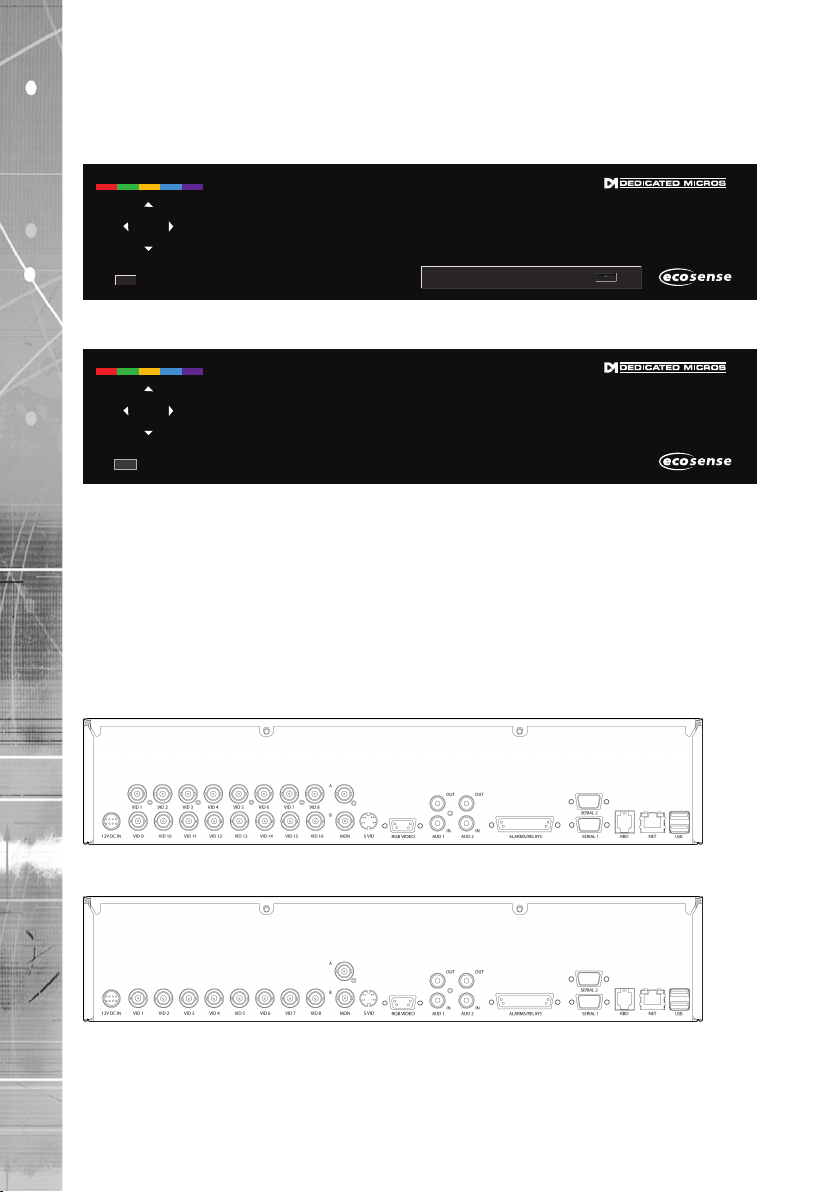
Rear Panel connections
16 Input model
8 Input model
10
Dedicated Micros ©2011
Page 11
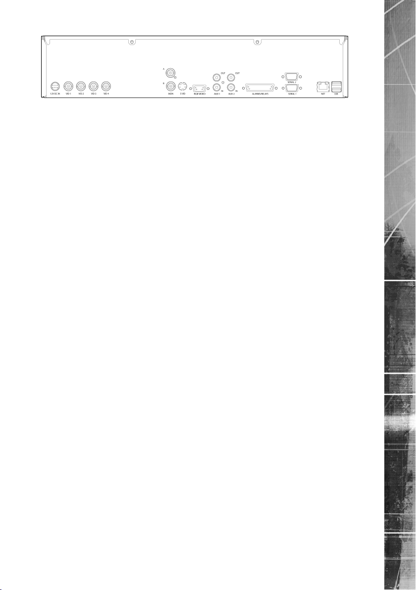
4 Input model
Video
VID1 to VID4/VID8/VID16 75Ω BNC composite video inputs 1V pk-pk
MON A 75Ω BNC composite monitor output, 1V pk-pk
MON B 75Ω BNC composite monitor output, 1V pk-pk
S Video S Video Connection
VGA VGA Monitor output
Audio
Audio IN 2x RCA (phono) socket, 8KHz/16KHz/22KHz sampling 75Ω input
impedance, 1V pk-pk
Audio OUT 2x RCA (phono) socket, line level <100Ω output impedance,1V
pk-pk amplication required
Data
SERIAL 1 RS-232 (3 wire)
SERIAL 2 RS-485 (2 wire)
USB 2x USB2.0 connectors
Note: No.USB connectors on the rear of the 4 channel unit. USB port located on front of unit.
NET RJ45 Ethernet network connector, 10/100 Mb/s Ethernet Network
KBD RJ12 connector for use with KBC01 or KBC02 Keyboards
Note: The KBD connection is not available on the 4 channel unit.
Alarms and relays
ALARMS IN 25 way (female) D Type 24V 200mA
17 General Alarm Inputs
Range of Alarm states are
i. 0 – 800R = Short circuit
ii. 800R – 2K = closed contact
iii. 2k – 12k = open contact
iv. > 12K = open circuit.
Note: 5 alarm inputs supported on 4 channel unit.
RELAYS Via 25 way (female) D Type rated at 24V 200mA
2 onboard light duty relay output (500mA@12V-48V Max)
Note: 1 relay output supported on 4 channel unit.
EcoSense
Power
POWER Input for 12v DC external power unit (supplied).
Dedicated Micros ©2011
11
Page 12
EcoSense
Installing the EcoSense Unit
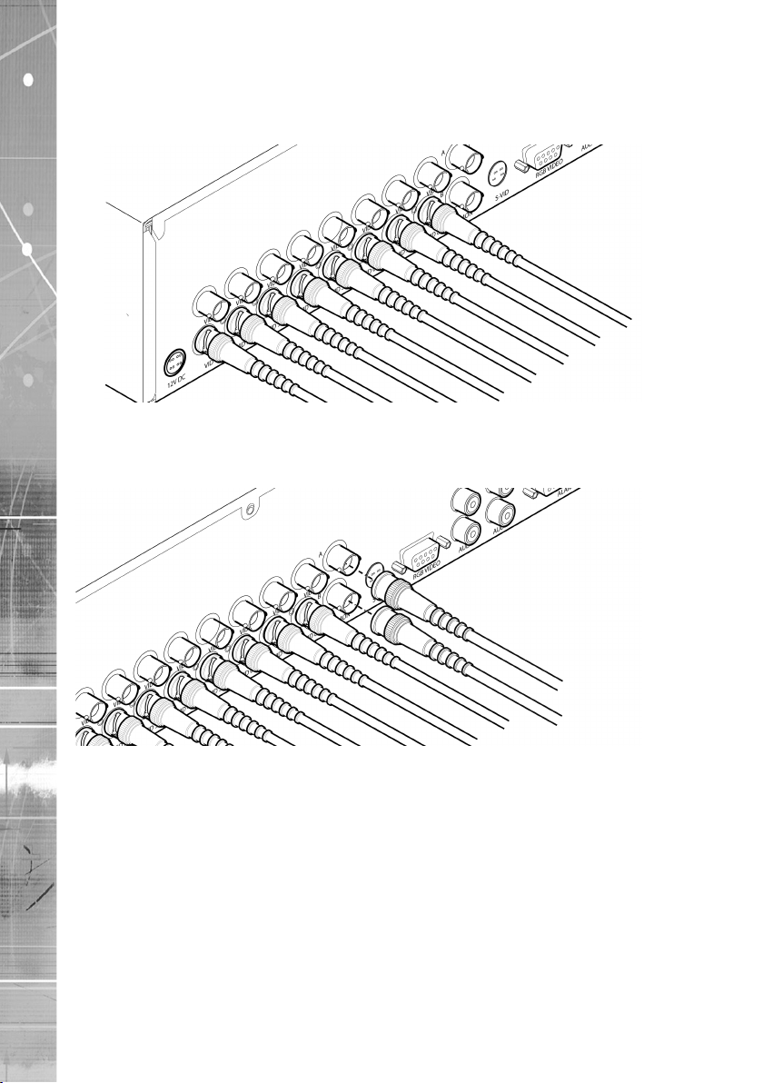
This procedure shows the sixteen camera input version.
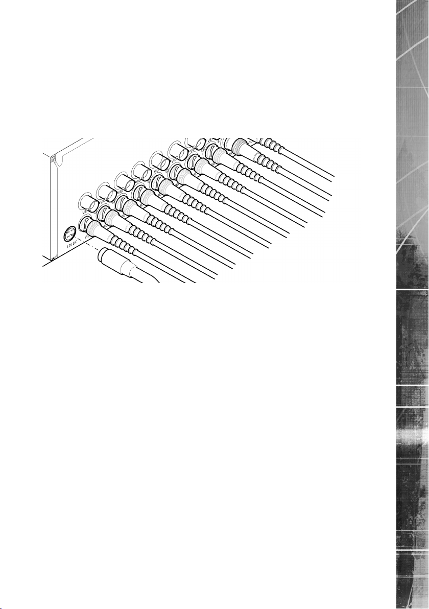
Step 1 Connecting Video
The unit supports up to 4, 8 or 16 connected Video Inputs (dependant on model) via the 75Ω BNC
connectors. Connect cameras to the video inputs, starting from input 1.
5.12
Step 2 Monitor
12
The unit supports a main monitor via ‘Mon A’ and a spot monitor via BNC labelled ‘Mon B’.
A monitor can also be connected via the S-Video or RGB Video outputs.
Dedicated Micros ©2011
Page 13
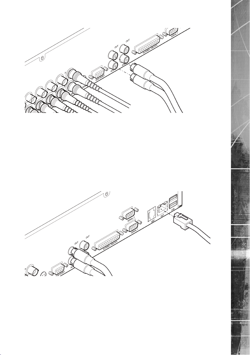
Step 3 Connecting Audio
The unit supports two channels of bi-directional audio, accessible through NetVu ObserVer. Connect
the audio equipment to the phono sockets AUDIO IN and AUDIO OUT. The audio channel defaults
to recording camera 1.
The following modes of operation are supported:
• Challenge – intruders from an RVRC.
• Listen – to local audio from a site at the RVRC.
• Record - local audio from a site with the video.
• Replay - all audio through a local Audio output (not supported when
Audio out is used as a challenge/PA source)
Note: The Audio output can be congured as a challenge output or as a replay output.
Step 4 Connecting to the Network
EcoSense
The unit supports a 10/100Mbps auto-detecting network port. Use a CAT5 cable to connect the unit to
the network.
Dedicated Micros ©2011
13
Page 14

EcoSense
Notes about IP Networks
Transmission Control Protocol/Internet Protocol - TCP/IP
The internet (and most other networks nowadays) use TCP/IP as the method of transporting data
over a network. When data is transferred over an IP network it is broken up into segments (by
the TCP) and sent as individual ‘packets’. Each packet is individually addressed (by the IP) with
destination and source information, and can then be sent down a different path, and even a different
sequence, across the network and reassembled at the other end. Data travelling on a network is
referred to as ‘trafc’.
TCP/IP uses the client/server model of communication in which a client (computer) requests a
service (camera image) by another machine (DVR) on the network. (In pure IP networks, the DVR
requests a camera image from an IP camera on the network.) TCP/IP communication is primarily
point-to-point, meaning each communication is from one point in the network to another point or host
computer.
There are many higher level protocols that use TCP/IP as a tool for transportation, including HTTP,
FTP, Telnet and SMTP
Dynamic Host Conguration Protocol - DHCP
Dynamic Host Conguration Protocol is a feature built into most routers. Routers control trafc on
a network by sending IP packets down the most efcient available route to their destination. If you
have a router on your network, then DHCP should be available to use. If it is not available, it may
have been switched off. Check with the network administrator to establish if this is the case, and
why it has been disabled/switched off. DHCP assigns Internet Provider (IP) addresses to devices
on a network to ensure that the network makes the most efcient use of the limited number of IP
addresses available to it. It removes the requirements for an administrator to keep track of all the
IP addresses on a network and which number is assigned to which machine. DHCP keeps track of
the network and assigns a free IP address to a unit as the unit connects to the network. However,
it also means that a unit will not always have the same IP address when it connects to a network.
The Internet is a network, and most Internet Service Providers utilise DHCP to connect users to the
Internet.
Domain Name System - DNS
Computers use IP addresses to communicate with each other over a network. These IP
addresses are 32 bit binary numbers expressed as four sets of three numbers (called octects), eg
565.898.785.124. These are not as easily remembered as the name of a server or a company. The
Domain Name System is a distributed database stored on the Internet that translates host names
into IP addresses, ie converts an easily remembered name or text string onto a four sets of three
numbers that the computer can use to look up the site you are looking for (a useful analogy is a
phone book for computers). This allows users to type in a humanly readable address and connect to
a point on a network or the Internet.
Dynamic Domain Name System - DDNS
Dynamic DNS makes use of the DNS system described above. Given that DHCP means that the IP address of a device can change every time it is connected to a network or the Internet, and DNS can link
an IP address to a recognisable string of text, Dynamic DNS allows a user to link a device to a string
of text and force the database to be updated with the device’s new IP address whenever it connects to
the Internet. Instead of a string of text being linked to an IP address in a static table, it is now linked to
a DDNS server. Whenever the device connects to the Internet, it updates the DDNS table with its new
IP address. ie it updates the computer phone book instantly on connection.
14
Dedicated Micros ©2011
Page 15
By default the unit is congured for DHCP i.e. the unit is automatically allocated an IP address from
a network DHCP server.
DHCP works by assigning an IP address at initial connection to the network. It is possible however
that this IP address can change without notication i.e. following power failure. It is therefore
recommended that the unit either has a xed IP address allocated to it, or that DNS is utilised and
a DNS name is set. A xed IP address can be assigned via the Conguration Menu pages:Network
Settings->Network->IP Address. The DNS name of the unit can be edited on the System->System
page. The DNS name is set by default as the serial number of the unit, which can be found on the
base of the unit and on the packaging the unit arrived in.
When the unit is powered up, the network address can be found by viewing on a local monitor and
navigating to Conguration Menu pages:System Settings->System->IP Address.
Refer to ‘Conguring The Unit’ for further guidance.
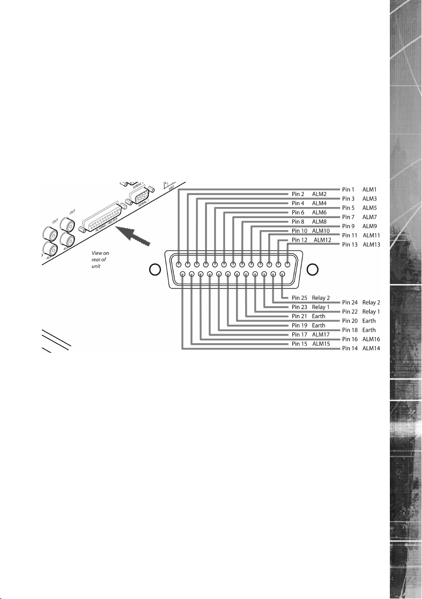
Step 5 Alarms / Relays
EcoSense
Alarms
The 4 channel unit supports 5 normally open/closed alarm inputs via the back panel, or one Global
keyswitch input with camera specic inputs congurable as entry/exit alarms. All other units supports
17 normally open/closed alarm inputs via the back panel, or one Global keyswitch input with camera
specic inputs congurable as entry/exit alarms.
Alarm/Relay Connector
Pin Alarm Input Connection
1 - 17 1-17
18-21 Earth Common
Relays
The unit support up to two 24V 200mA relays
Relay Connector
Pins Connection
22 Relay 1 signal
23 Relay 1 ground
24 Relay 2 signal
25 Relay 2 ground
Note: The 4 channel unit supports one relay output.
Dedicated Micros ©2011
15
Page 16
EcoSense
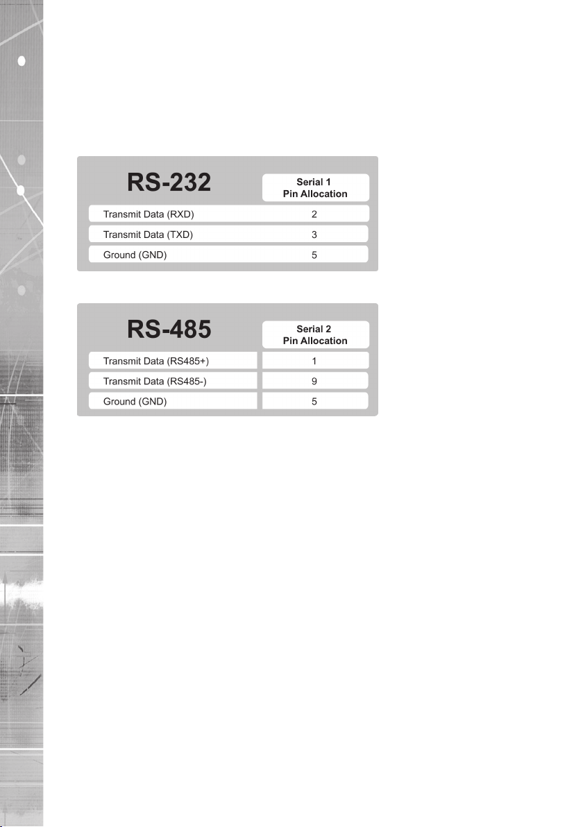
Step 6 Connecting Serial Ports
Serial port 1 offers RS-232 connectivity, serial port 2 offers RS-485 connectivity.
Serial ports have two main uses:
1. Connecting twisted pair telemetry for PTZ cameras.
2. Debug operations.
RS232
RS485
5.16
6.1
Step 7 Connecting a Keyboard
The unit supports Dedicated Micro keyboards DM/KBC1 and DM/KBC2. Connect either of these
keyboards via the KBD connector socket on the rear panel.
Note: The optional Keyboard is not supported on the 4 channel unit.
Note: Refer to the Unit Operation section of this manual for further guidance regarding the
supported keyboards.
16
Dedicated Micros ©2011
Page 17
Step 8 Connecting DM Oracle, 2060 & 2040 Domes
A DM Oracle, 2040 or 2060 Dome can be connected via RS485 twisted pair cabling.
The dome address should be set according to the camera number of unit (1-16).
Pin connections for RS485 connection to a Dennard dome on serial port 2 are:
Dome Cable Pin Connections
Yellow 1 TX+
Green 9 TX-
Step 9 Connecting Power
Connect the 12v DC power adaptor (supplied) to the unit and then to the wall socket, or to a fused
spur connection. To be compliant with wiring regulations in some countries, an Alarm/Security device
should be connected to a fused spur and not a wall outlet socket (check local regulations before
installation).
EcoSense
Dedicated Micros ©2011
17
Page 18

EcoSense
Accessing & Conguring the Unit
The unit can be congured either on the local monitor or over the network using a PC with Internet
Explorer or similar browser. Both have near identical menu interfaces.
Accessing the menus on a local monitor
Accessing the menus on a PC web browser
Default DNS Address
1. The Conguration pages can be displayed on a local monitor (connected to BNC
Connector ‘Mon A’ on the rear of the unit). When connected, point the IR Remote
Control at the front of the unit and press the MENU button.
Note: If the IR Remote Control does not open the conguration menus, press the DVR button to
make sure it is in DVR mode, then press the MENU button again.
The unit can be located on the network by using either the IP address or the DNS name (if DNS is
available on the network). The IP address will be automatically assigned on startup if your network is
DHCP capable. Most networks will be DHCP and DNS capable. The DNS name is set by default as
the serial number of the unit, which can be found on the base of the unit and on the packaging the
unit arrived in. This can be edited in the unit conguration pages.
For information on locating the unit’s IP address via a PC and serial port connection, refer to
Appendix E.
It is recommended that a DNS (Domain Name Server) address be congured. Assigning a
recognisable name can help a remote user to locate the unit.
If no System name is allocated to the unit, the default DNS address will be:
machin_serial_number.yourdomain.com
• <machine serial number> is displayed in the System menu
page and also on the underside of
the unit.
• <yourdomain> is the name assigned to your
DNS network.
The default DNS address can be renamed via the System->Attributes menu. Following renaming,
the DNS address will be:
yourname.yourdomain.com
• ’ yourname‘ is the name assigned via the
Network menu.
• <yourdomain> is the name assigned to your
DNS network
Note: To activate an assigned DNS address, it will be necessary to reboot the unit. The unit can
be rebooted via System Settings:>Maintain-> Reset.
IMPORTANT: To set the time and date on the unit, navigate to System Settings->Time and Date.
Accessing the Conguration Webpages
To access the unit conguration webpages:
1. Launch Internet Explorer (or similar web browser package).
18
Dedicated Micros ©2011
Page 19
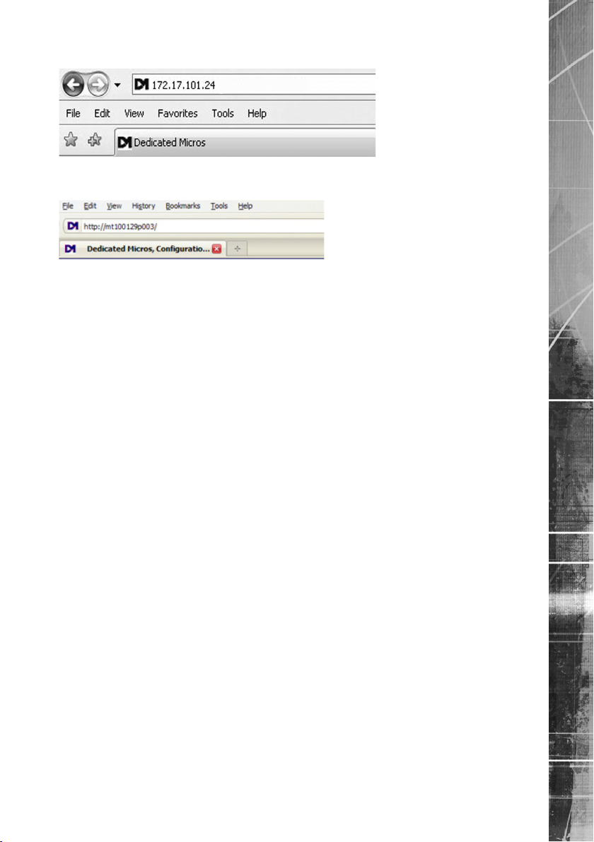
2. Type the URL for the unit (IP or DNS address).
Alternatively, the DNS address can be typed directly into the address bar of a web
browser.
Note: If the unit is subsequently assigned a xed IP address, its DNS address can no longer
be used
Note: The unit’s DNS address can be changed to something more memorable or meaningful than
its serial number by editing the System name option in the System conguration page.
3. The Opening menu page will be displayed.
EcoSense
Dedicated Micros ©2011
19
Page 20
EcoSense
6.13
Remote Control
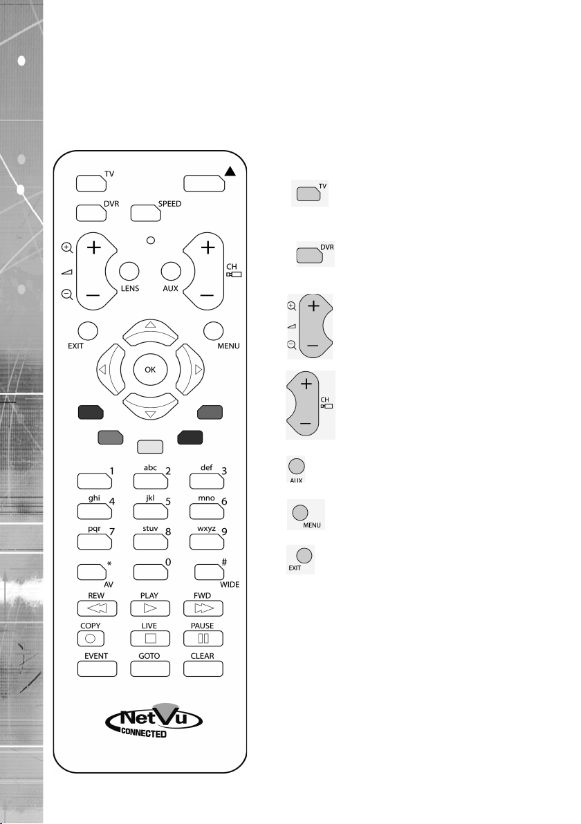
The IR Remote Control offers all the control functionality required to navigate the menus.
Note: Not all buttons on the IR Remote Control are relevant for the Unit.
Key Button
Switches the Remote Control to ‘TV’
mode and sends codes understood by
common TV sets.
Switches the Remote Control to ‘DVR’
mode. Note the DVR mode is the
default mode of operation.
Use the Zoom button to zoom in/out
with a selected camera. Also used to
zoom (x2) into Live or Playback images.
Use this button to cycle through
available cameras.
This button should be pressed (followed
by a numeric entry) to carry out auxiliary
actions on a PTZ camera.
Press the Menu button to enter the
Conguration menus.
Press the Exit button to exit the
Conguration menus.
20
Dedicated Micros ©2011
Page 21
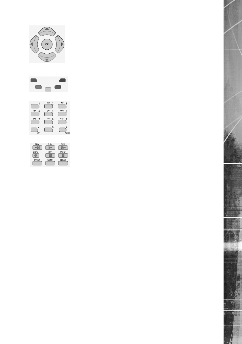
menu screens and accept changes. Also use for PTZ telemetry control
Use the Directional and OK buttons to navigate through the
of cameras.
Use the Softkeys (Red, Green, Yellow, Blue Purple) to directly access
the corresponding function displayed on the menu screen.
The Number pad should be used to select specic cameras and preset
positions when available.
Use the Playback buttons to interrogate recorded images. Use the LIVE
button to switch from Playback or menus to a LIVE display.
EcoSense
Dedicated Micros ©2011
21
Page 22

EcoSense
Using the IR Remote Control
Press the MENU button to access conguration menus via a connected local monitor. The menu will
have a red indicator highlighting the rst option. Select a main menu heading to open a drop down
list of further sub-options. Press the Down Directional button to highlight the next menu option, press
OK to open the highlighted menu.
Press the Right Directional button to highlight the rst editable parameter on the screen.
Use the Left/Right/Up/Down Directional buttons to move between elds.
Select OK to start editing a eld (the option will be outlined in green).
Use the Up/Down Directional buttons to change the settings within an editable eld.
Use the OK button to accept a new setting. Use the coloured softkeys to select the accompanying
colour option on screen i.e. red button to select the red option. To undo changes made to any menu,
select the Refresh (Purple) option.
Note: See below for information on entering alpha-numeric data.
Using the Front Panel Interface
The Conguration and Viewer menus can be navigated and edited using the unit’s front panel
interface (via a connected local monitor).
Navigate the menu tree via the Up/Down Directional buttons. When a menu is highlighted, open by
pressing the OK button.
Use the Left/Right/Up/Down Directional buttons to move between elds.
Select OK to start editing a eld (the option will be outlined in green).
Use the Up/Down Directional buttons to change the settings within an editable eld.
Use the OK button to accept a new setting.
Use the colour bar (Red, Green, Yellow, Blue and Purple) to directly access the
corresponding function displayed on the menu screen i.e. red panel to select the red option.
Note: See below for information on entering alpha-numeric data.
Entering Alpha-Numeric Data via a Local Monitor
Numeric or text data is entered using the on-screen Virtual Keyboard (Arrow Key Editor).
To display the Virtual Keyboard, navigate to the relevant text input box using the Directional buttons
and double press the OK button twice on the IR Remote Control or Front Panel Interface. The Virtual
Keyboard is displayed.
Use the Directional buttons to move between characters, use the OK button to select a character.
Select ‘Submit’ to enter details, press ‘Cancel’ to exit without entering any text.
Alpha-numeric data can also be entered in either upper or lower case format by ‘multi-tapping’
a relevant button. For example, with the cursor located in the text entry window of the Virtual
Keyboard, repeatedly tap button ‘2’ to cycle through the following characters: 2,A,a,B,b,C,c,2 etc.
To select one of these characters, simply stop tapping the button when the chosen character is
displayed. The cursor will then progress, ready for the next character entry.
Note: A USB Keyboard (not supplied) can be connected via one of the USB ports on the unit. The
USB Keyboard can then be used to enter alpha-numeric data via the local menus.
22
Dedicated Micros ©2011
Page 23

Using a USB Mouse or the Webpages
Navigate the menus by clicking the tabs displayed on the left of the menu headings (on the menu
tree). The rst option is highlighted with a red tab. Select a main menu heading to open a drop down
list of further sub-options.
Highlight an editable eld by clicking on it directly.
If viewing pages locally, enter alpha numeric data via the Arrow Key Editor (see above). If viewing
remotely, enter via the PC keyboard. If available, click on the drop down menus to select settings.
Note: A selected item in the drop down list will appear highlighted.
Navigating away from a page (clicking on a different option on the menu tree) will automatically save
any changed settings. To undo changes made to any menu, select the Refresh (Purple) option.
Using a Supported Dedicated Micros Keyboards (DM/KBC1 & DM/KBC2)
The unit can also be controlled using an optional Dedicated Micros keyboard (except the 4 way
unit). This is connected via the KBD connector on the rear of the unit and provides the same control
functions as the I.R Remote Control.
Note: Refer to ‘Using the optional Keyboards (DM/KBC1 & DM/KBC2)’ for further guidance.
EcoSense
Dedicated Micros ©2011
23
Page 24
EcoSense
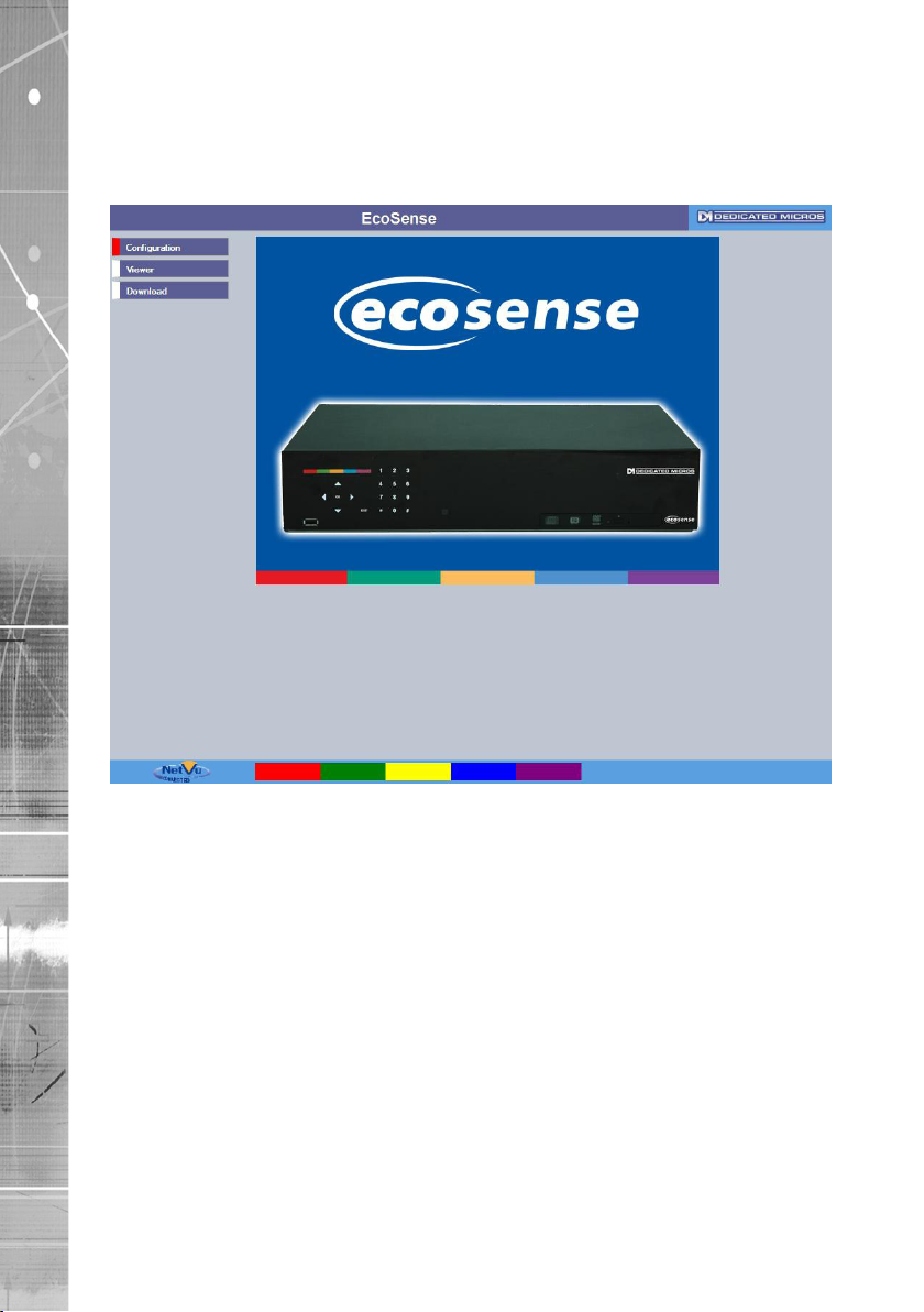
Main Menu
When rst accessing the unit, the main menu will be displayed. This menu allows access to the
Conguration menus, the Viewer menus and also several Download options.
Note: The Download options will only be available if viewing remotely via an IP connection.
24
Select the Conguration menu tab to access the unit’s Conguration menus. Refer to ‘Navigating the
Conguration Menus’ for further guidance.
Select the Viewer menu tab to access the unit’s Viewer function. Refer to ‘Unit Operation’ for
guidance on the numerous Viewer features.
Select the Download menu tab to access the various Download sub-options. Select from:
• Product Manual Select to open an electronic version of the
Installation & Operation Guide.
• ObserVer Manual Select to open an electronic version of the NetVu ObserVer
User Guide. NetVu ObserVer is a free video management
software package from Dedicated Micros. It allows users to
seamlessly view distributed images from any
‘NetVu Connected’ product.
• NetVu ObserVer Select to download the NetVu ObserVer video
management software.
• Java (JRE) Select to download the Java (JRE) software (from the unit).
This software is required to successfully view Conguration
and Viewer menus remotely.
Dedicated Micros ©2011
Page 25

IMPORTANT: By default, no Usernames and Passwords are required to access any of the
various menus. Usernames and Passwords can however be added to regulate
access to the Conguration and Viewer menus. Refer to the ‘Display Settings->
User Accounts’ menu for information on establishing Usernames and Passwords.
EcoSense
Dedicated Micros ©2011
25
Page 26
EcoSense
Navigating The Conguration Menus
The menu tree provides access to the conguration menus.
The conguration pages are navigated using the menu tree (displayed on the left of each page).
Selecting one of the menu options will display the relevant page. Associated sub-menus will then be
available.
26
Relevant menus can also be accessed directly from other menu screens via the coloured softkey
options shown at the base of each menu. The options available will depend on the menu being
viewed. Select a softkey option by pressing either the corresponding button on the IR Remote
Control (if viewing the menus locally), or by selecting the relevant option via the PC mouse (if
viewing the webpages).
Note: Any changes made via the webpages are automatically saved when the page is closed. To
‘manually’ save changes, select the Save option.
Dedicated Micros ©2011
Page 27

System
The menus under the System Settings heading allow the unit’s core settings to be viewed, changed
and the system software upgraded.
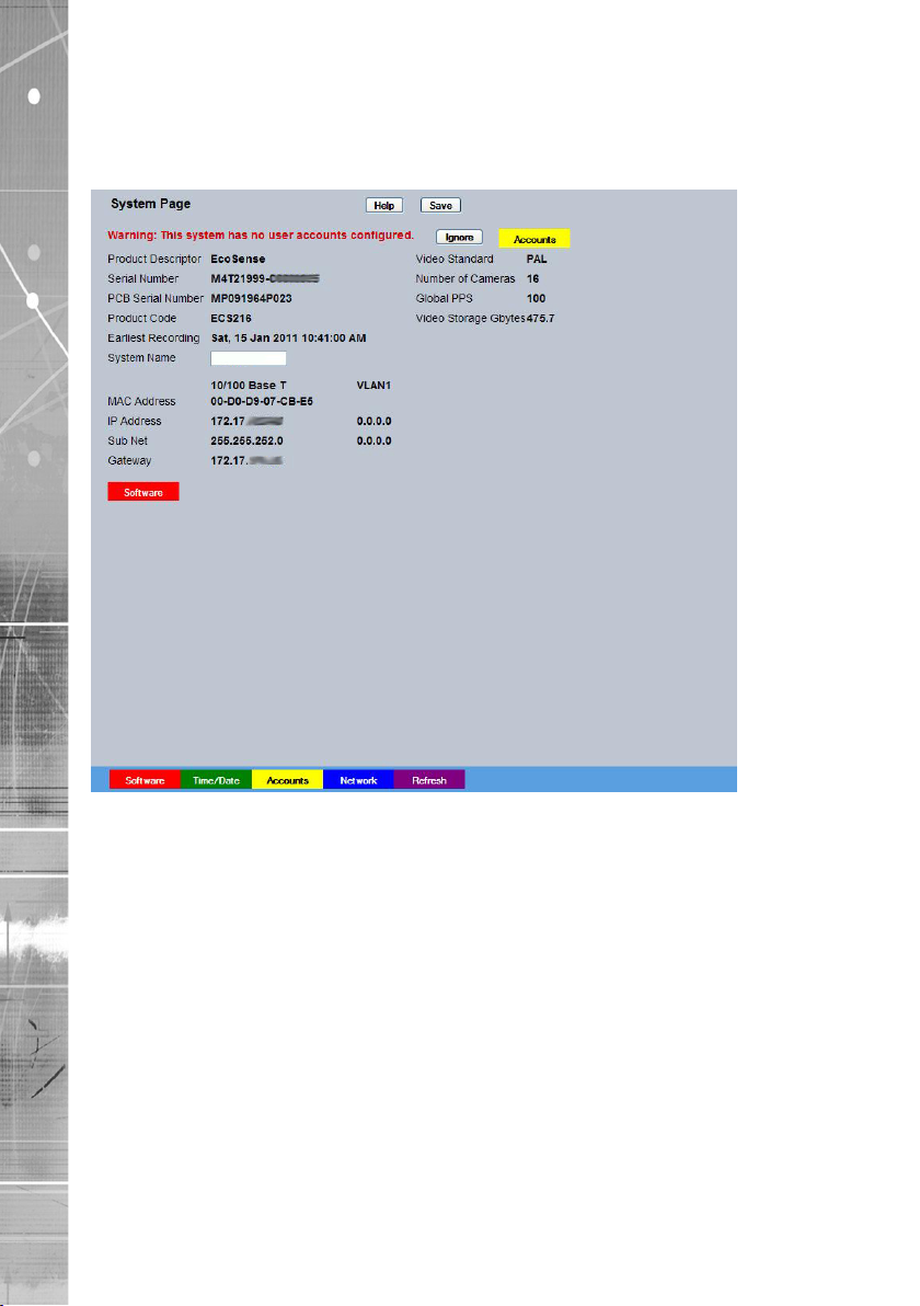
The System option displays details about the unit including the IP address, unit serial number, MAC
address and software version.
The Status page displays information about the unit’s operating condition, shows how long the unit
has been operating and the reason for the last reset. It also shows camera status and displays any
failed cameras.
The Language page allows the system language to be set. The language can also be changed for
the current session only.
The Time and Date page allows the unit time and date settings to be adjusted, including setting the
timezone.
The Serial Ports page allows each of the two serial ports to be individually congured for one of a
range of operations, including, debug, PPP and telemetry.
The Audio page shows the settings available for each of the audio channels and allows conguration
of audio quality.
The Features page allows control of the different features that are available within the software
including Email reporting, webcam support and control of the display resolution.
The Maintain page allows the current conguration to be saved, and for previously saved settings to
be loaded. It also enables easy upgrade of the system software.
The PowerScript Mgmt page allows installed PowerScripts to be activated/deactivated on start-up.
EcoSense
Dedicated Micros ©2011
27
Page 28
EcoSense
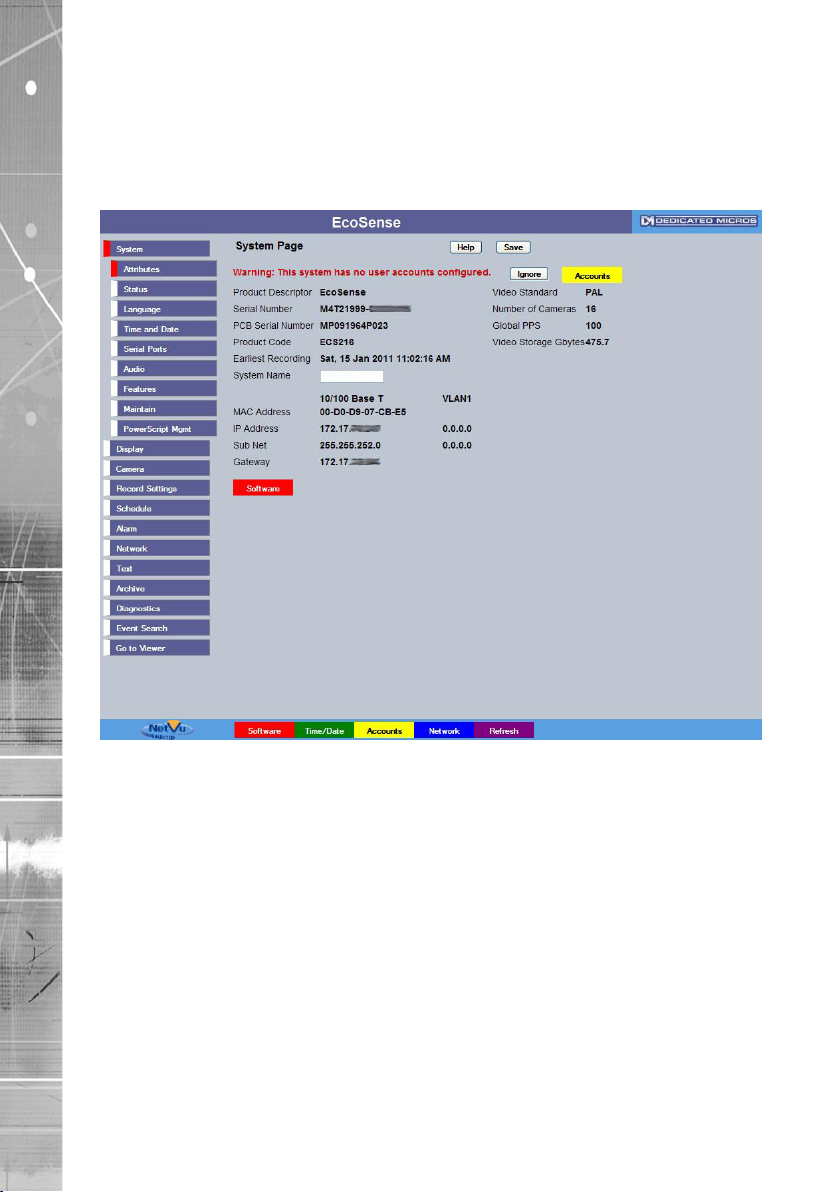
Attributes
6.13
This menu shows the general information about the unit including the version of software installed,
the unit’s serial number and the allocated DHCP IP address.
28
Product Descriptor Details the product model.
Serial Number Identies the serial number of the specic unit.
PCB Serial Number Displays the Printed Circuit Board serial number of the unit.
Product Code Displays a code identifying the unit’s specication.
Earliest Recording Displays the date/time of the earliest recording held on the unit.
System Name This eld can be edited to allocate a name to the unit. This is
displayed when the unit is accessed via NetVu ObserVer and is
sent when transmitting information to a Remote Video Response
Centres (RVRC).
Number of Cameras Shows the number of camera channels on the unit.
Global PPS Details the Global PPS (Pictures Per Second) recording rate for
all cameras.
Video Storage Gbytes Highlights the available video storage capacity in Gigabytes.
Video Standard Displays the video standard adopted by the unit i.e. PAL, NTSC.
MAC Address This is the MAC address assigned to the unit.
IP Address This is the IP address allocated to the unit.
Sub Net This is the subnet of the network where the unit is located.
Gateway This is the IP address of the default gateway (router) assigned by
the DHCP server.
Dedicated Micros ©2011
Page 29
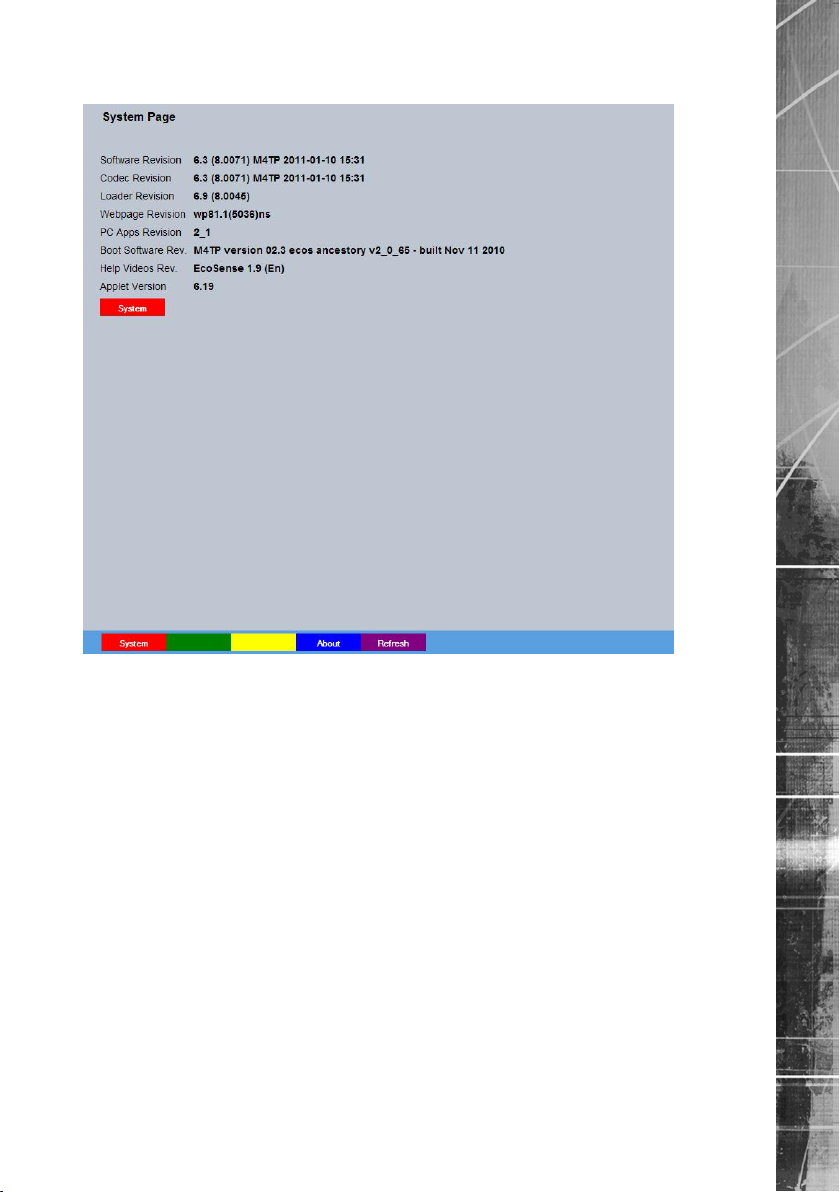
Software Menu
EcoSense
Software Revision This identies the version of software the unit is running.
Codec Revision This identies the codec version the unit is running.
Webpage Revision This identies the webpage version the unit is running.
Framestore Revision This identies the Framestore Revision the unit is running.
PC Apps Revision This identies the revision archive of the Viewer and associated
PC Apps software.
Boot Software Rev. Displays the infrastructure componentry software revision.
Help Videos Rev. This identies the version of Help Videos installed on the unit.
Note: Refer to ‘Go To Viewer->Help Videos’ for guidance on viewing the imbedded Help Videos.
Applet Version This identies the applet version installed on the unit
Note: Refer to ‘Display Settings->Viewer Defaults’ for guidance on using a remote applet (this can
lessen load times when accessing multiple DVRs/Servers).
System (Red) Select this option to return to the System menu.Software Revision
This identies the version of software the unit is running.
Dedicated Micros ©2011
29
Page 30
EcoSense
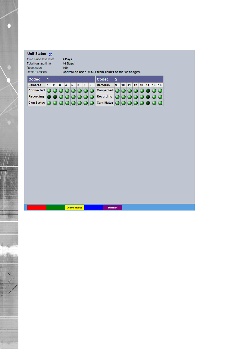
Unit Status
This menu details information regarding the status of the unit, notably the total time the unit has
been operating and the time since its last reset.
30
Time since last reset Details the time since the unit was last reset.
Total running time Details the total time the unit has been operational.
Reset code The last reset code used is displayed.
Restart reason The reason for the last restart is displayed i.e. Controlled
User Reset.
Codec Two codecs are installed within the unit.
Cameras Shows which cameras are assigned to the displayed codec.
Connected Those camera channels with cameras connected will be
highlighted light green. Those not in use will appear dark green.
Recording Those camera channels that are currently recording are
highlighted light green. Those not recording will appear
dark green.
Cam Status Those camera channels where the connection is deemed to
be functioning correctly will be highlighted light green. Those
deemed to have failed will appear red. Camera channels with no
connected camera will appear dark green.
Dedicated Micros ©2011
Page 31

Alarm Status
This menu details information regarding the status of the unit’s alarm contacts, alarm zones and
relay outputs.
EcoSense
Alarm Contacts/Zones/Relay Outputs Alarm Contacts, Alarm Zones and Relay Outputs that are
in an ‘active’ state are shown light green. ‘In-active’ ones
appear dark green (not illuminated).
Note: The 4 channel unit has 5 alarm contacts and 1 relay only.
Dedicated Micros ©2011
31
Page 32

EcoSense
About
This menu allows access to numerous system information pages. Select the an icon to view the
relevant pages.
32
Dedicated Micros ©2011
Page 33

Logs
The log les stored in the unit can be accessed from this page. Selected logs are displayed on the
page below.
EcoSense
About (Blue) Select to open the System->Status->About page.
Refresh (Purple) Refreshes the information on the current page.
Dedicated Micros ©2011
33
Page 34

EcoSense
Language
This menu allows the system language to be set. Changing the System Language will effect all
menu pages. If required, the language can also be changed for the current session only.
34
System Language Select to change the system language setting.
Reset (Red) Select to reset the unit.
Note: The unit MUST be reset to implement system language changes, refer to
System Settings->Maintain for guidance on resetting the unit.
Session Language Select to change the language settings for the current
session only.
Choose Select to immediately activate session language changes.
Reset (Red) Select to cycle the power to the unit.
Refresh (Purple) Refreshes the information on the current page.
Dedicated Micros ©2011
Page 35

Time and Date
This menu allows the time and date to be set on the unit. Required timezone information can also be
established and the unit time synchronised to that of the PC being used to view the webpages.
EcoSense
System Time The current system time and date is displayed.
Current Time Zone Displays the currently selected time zone settings.
Time Format As default, the time displayed is in 12 hour format. This can be
changed to 24 hour if required.
Date Format As default, the date is entered dd/mm/yy. It can also be displayed
as mm/dd/yy or yy/mm/dd.
Set Time Enter a current time for the unit.
Set Date Enter a current date for the unit.
Set Time (Green) When current time/date as been entered, select this button to
implement changes.
Time Zone Select the relevant timezone offset from the accompanying drop
down menu.
SNTP Server A Simple Network Time Protocol (SNTP) server allows external
devices to connect and set their current date and time settings to
that of the SNTP. If required, enter the SNTP server IP
address here.
Note: It is recommended that an SNTP server is congured. Suitable networked SNTP servers
can be found here: http://support.ntp.org/bin/view/Servers/NTPPoolServers
Dedicated Micros ©2011
35
Page 36

EcoSense
Alternatively most DHCP and DNS servers also run SNTP services. Contact your system
administrator for further assistance.
PC Time Displays the system time of the PC currently being used to view
Sync Time (Blue) Use this button to synchronise the time of the unit to that of the
Note: The PC Time and Sync Time options will only be available if viewing the menu via
the webpages.
Reset (Red) Select to cycle the power to the unit.
Set Time (Green) When current time/date as been entered, select this button to
System (Yellow) Select to open the System->Attributes page.
Sync Time (Blue) Use this button to synchronise the time of the unit to that of the
Refresh (Purple) Refreshes the information on the current page.
the webpages.
PC being used to view the webpages.
implement changes.
PC being used to view the webpages.
36
Dedicated Micros ©2011
Page 37

Serial Ports
This menu allows conguration of the unit’s Serial ports, refer to ‘Installing the Unit’ for
installation information.
EcoSense
Serial Port These are the four serial ports available.
Port Cong The serial ports can be congured to specic uses.
None Switches port off
Debug Sets port for serial communications
PPP Sets port for Point to Point Protocol
Telem Sets port for Telemetry purposes
Comm Sets port for Comms purposes
EPOS Sets the serial port for connection to an
Note: It is recommended that Serial port 1 be set for ‘Debug’ operations.
Interface Type Choose the type of serial interface being used. Select from
Baud/Parity/Data/Stop/Flow Control
Note: When a telemetry protocol is selected, these settings will default to pre-determined values
and should not normally be altered.
Dedicated Micros ©2011
Select from:
EPOS (Electronic Point Of Sale) device
RS232, RS485 or RS422.
These options allow the Serial port communication settings to
be congured.
37
Page 38

EcoSense
Protocol This is a drop down list of serial telemetry protocols supported by
Note: Refer to ‘Appendix F’ for a full list of supported telemetry protocols.
Reset (Red) Select to cycle the power to the unit.
Maintain (Green) Select to open the System->Maintain page
Text In Img (Yellow) Select to open the Features & Text->Text->Text In Image page
Camera (Blue) Select to open the Camera Conguration page (below).
Refresh (Purple) Refreshes the information on the current page.
the unit.
Camera Conguration
This page allows conguration of some features on all 16 cameras available to the unit.
38
Title Titles assigned to each camera are displayed.
Mode The settings will default to ‘Colour’. If Monochrome cameras
are used, select ‘Mono’. Selecting ‘Mono’ will remove colour
patterning. If a particular channel is not in use or the camera has
failed, select ‘Not Connected’. ‘Remote Codec’ is used for NetVu
Connected video sources. ‘IP Camera’ is used for all NetVu
Connected cameras and 3rd party units.
Term The unit will automatically terminate the camera input with 75Ω.
This should be disabled if the video feed is looped through to
another device.
Fail Rep Select this option to activate a Failure report in the event of
camera connection failure (video loss).
Dedicated Micros ©2011
Page 39

Buzzer Select this option to activate the onboard buzzer to report in the
event of camera connection failure (video loss).
Cam Setup (Red) Select to open the Camera->Setup page
Serial (Blue) Select to open the System->Serial page
Refresh (Purple) Refreshes the information on the current page.
EcoSense
Dedicated Micros ©2011
39
Page 40

EcoSense
Audio
The Audio menu allows settings for the bi-directional audio channels to be edited. Audio can be
recorded from camera inputs via input 2. Challenge audio i.e. originating from an Operator using
NetVu ObserVer at a Remote Video Receiving Centre (RVRC) can be recorded via input 1. This
combined audio is then available on Audio Output 1, refer to ‘Installing the SD Advanced for audio
hardware installation information.
40
Audio 1/2 Use the drop down box to assign an audio function to each input,
‘Local’ is Audio recorded from local inputs, ‘Challenge’ audio
originates from an Operator using NetVu ObserVer at a Remote
Video Receiving Centre (RVRC).
Audio Recording Select ‘Enable’ to activate Audio recording. Note that this is a
global action which when Enabled, will result in all audio received
by the unit being recorded to the HDD.
Record Audio Challenge Select this option to record an audio challenge received via an IP
connection i.e. originating from a remote client.
Record Gain This option allows the Record Gain level to be set. This is the
base setting from which the AGC (Automatic Gain Control) will
operate. Select from 1 to 15. The default and recommended
setting is 15.
Playback Volume Select a volume setting between 1 to 64 for audio playback.
Record AGC Select this option to activate the AGC function. AGC helps
produce a better quality recording by removing background
noise/distortion.
Dedicated Micros ©2011
Page 41

Record uncompressed Select this option to record audio in an uncompressed format.
Note: Recording in uncompressed format will signicantly increase the disk space used.
Reset (Red) Select to cycle the power to the unit.
Refresh (Purple) Refreshes the information on the current page.
EcoSense
Dedicated Micros ©2011
41
Page 42

EcoSense
Features
These menus enables the activation of numerous system features. Features are grouped within four
sub-menus: System, Network, Video and Other.
System
42
Keyboard Touch Sensitivity Select to alter the sensitivity of the touch controls on the front of
the unit. The higher the setting is (up to 32), the more sensitive
the controls will become.
User Logging Enable this option to activate User Logging, refer to ‘Appendix D’
for further information regarding the User Logging function.
Enable External Modules Select to enable any connected RS485 alarm modules.
Text in Images Select this option to activate the Text in Images function. For more
information refer to ‘Text-Text In Image’.
Note: When de-selected here, the ‘Text in Image’ menu will no longer be displayed in
the menu tree.
Email Reporting Select this option to activate the Email Reporting function, refer to
‘Network Settings->Email’ for more information.
Note: When de-selected here, the ‘Email Reporting’ menu will no longer be displayed in
the menu tree.
Dedicated Micros ©2011
Page 43

Keyboard Enable (485 bus) Select to enable a connected RS485 Keyboard unit.
Note: This will reassign the onboard RS485 bus to keyboard use and disable any RS485
telemetry.
IMPORTANT: Enabling this feature will inhibit the use of a KBC1 or KBC2 keyboard.
Remote Reporting Select this option to activate the Remote Reporting function, refer
to ‘Network Settings-Remote Reporting’ for more information.
Note: When de-selected here, the ‘Remote Reporting’ menu will no longer be displayed in
the menu tree.
Automatic FTP Download Select this option to enable automatic FTP downloads to upgrade
the unit and/or the webpages, refer to ‘Network Settings-FTP
Download’ for more information.
Note: When de-selected here, the ‘Automatic FTP Download’ menu will no longer be displayed in
the menu tree.
SMB Server Support Select this option to activate the SMB (Server Message Block)
le sharing function. When activated, the SMB protocol allows
the unit to access PCs operating the Windows operating system
(and Linux machines running Samba). This enables sharing
of les and directories to/from the unit. The name of the SMB
Workgroup on the network must be correctly entered in the SMB
Workgroup option (see below). It is important that the Server
Name assigned to the unit via ‘Network Settings->Server Name’ is
unique within the workgroup being used. To access the unit via a
PC running SMB (and has access to the same Workgroup); open
My Network Places-Entire Network- Microsoft Windows Network.
The Workgroup containing the unit and PC(s) should then be
available. Files and folders can then be copied/added as required.
Note: Use the 10/100Mbps network option ‘Net 2’ for SMB purposes (the unique Server Name
must be assigned via ‘Network Settings-Server Name’).
Camera Masking Select this option to activate the Camera Masking function. When
activated, any attempt to cover a connected cameras lens will be
noted and an alarm event will be logged.
System (Yellow) Select to open the System->Features->System page
Network (Green) Select to open the System->Features->Network page
Video (Yellow) Select to open the System->Features->Video page
Other (Blue) Select to open the System->Features->Other page
Refresh (Purple) Refreshes the information on the current page.
EcoSense
Dedicated Micros ©2011
43
Page 44

EcoSense
Network
44
Secondary Web Port If the default port setting for web serving has already been
allocated, it is possible to congure a second port number
i.e. the secondary web port can be set to 8000 if the default web
port (80) is blocked by the network or rewall.
Samba Workgroup Enter the name of the Samba workgroup to enable sharing of
les and directories to/from the unit. To access the unit via a PC
running SMB (and has access to the same Workgroup); open
My Network Places-Entire Network- Microsoft Windows Network.
The Workgroup containing the unit and PC(s) should then be
available. Files and folders can then be copied/added as required.
Auto IP Override This is set to default at the factory, which means that the
camera will attempt to connect to a Closed IPTV network if one
is detected. This can be overridden to prevent the attempt to
connect by setting to enabled.
Max Client Connections This setting limits the number of client connections to the server.
The default value is 256 but could be increased if there is heavy
network trafc.
ARP Cache Size This setting limits the number of cache entries available in the
ARP table. The default setting of 256 is adequate for most
instances
TCP Reassembly Queue Limit This setting limits the maximum number of TCP segments
allowed in the reassembly queue, to protect against a common
DoS attack.
Dedicated Micros ©2011
Page 45

System (Yellow) Select to open the System->Features->System page
Network (Green) Select to open the System->Features->Network page
Video (Yellow) Select to open the System->Features->Video page
Other (Blue) Select to open the System->Features->Other page
Refresh (Purple) Refreshes the information on the current page.
EcoSense
Dedicated Micros ©2011
45
Page 46

EcoSense
Video
46
Detected Video Standard The unit automatically detects the video standard being used i.e.
PAL/NTSC.
Video Resolution (h x v) This is the default display resolution when viewing the unit’s menu
pages.
Deinterlace mask When Enabled, this option will improve the appearance of moving
objects by applying a deinterlace mask that minimises the comb
effect that can be visible when recording high motion scenes in
4CIF mode. It is recommended that this option be enabled when
recording in 4CIF mode.
Comb Filter Enable this option to activate the Comb Filter function. Comb
Filter can help improve the ne details of a video signal image by
ltering the luminance and chrominance separation process.
Disable Transcoding Select to disable the unit’s transcoding capabilities. In normal
circumstances this should always remain enabled, however it can
be useful to disable the feature when conducting maintenance.
Dedicated Micros ©2011
Page 47

Segment Aspect Ratio This setting control how a 4:3 image is displayed in a multi-screen
or wide screen format on the local viewer. The available display
segment changes depending on the number of multi screen
images selected for display.
Stretch forces the image to ll the available display segment. This
may result in some distortion of the display image.
Zoom Fit forces the frame to ll the available segment completely
and proportionally. Consequently some of the image at the top
and bottom of the frame may be cropped.
Frame Fit forces the frame to ll the available segment
proportionally, resulting in black bars left and right on some multi
display choices.
EcoSense
Dedicated Micros ©2011
47
Page 48

EcoSense
Other
48
Auto Update Web Variables Congures the unit to update all system variables required for an
automatic upgrade without requiring conrmation. Do not check
this box if a customised applet is used.
Enable Event Search Select to enable the Event Search option. When enabled, the
option will appear within the Conguration Menu tree, refer to
‘Navigating the Conguration Menus->Event Search’ for further
details.
Enable RVRC page Select this option to activate the RVRC Remote Set/Unset/
Override function, refer to ‘Record Settings-RVRC’ for
more information.
Note: When de-selected here, the ‘RVRC’ menu will no longer be displayed in the menu tree.
Dedicated Micros ©2011
Page 49

Maintain
This menu allows the unit to be reset and a software upgrade to be performed via an inserted -RW
CD/DVD or a connected USB device. Current unit settings can also be saved for future use and
previously saved settings restored.
EcoSense
Conguration
Default (Green) Select to return the unit to its factory default settings.
Note: Selecting the Default button will cause the system to reboot.
Save (Purple) Select to save current unit settings to the selected media.
Restore (Blue) Select to restore previously saved settings from the selected
media.
Note: Selecting the Restore button will cause the system to reboot.
To/From Select the relevant media device to save to or restore from i.e.
USB or CD/DVD.
Note: The writer only accepts -RW media.
Server
Reset (Red) Select to cycle the power to the unit.
IMPORTANT: To upgrade the unit, insert a media device containing relevant software upgrades
and select ‘Reset‘.
Note: For the latest software upgrades, please refer to the Dedicated Micros
website: www.dedicatedmicros.com
Dedicated Micros ©2011
49
Page 50

EcoSense
PowerScript Mgmt
This page enables you to select which PowerScripts are automatically run when the unit starts up.
Use the tickboxes below to select which scripts you require and then click Save. You will need to
restart your unit for the changes to take effect.
NOTE: Clicking Save will alter DEFAULT.C, if you already have a custom PowerScript on your unit
which uses the DEFAULT.C le, please contact your regional Technical Support before
using this page.
50
PowerScript Identies which powerscript is being congured to run
Run At Startup Species whether the powerscript will run when the unit starts up
Description Displays the description associated with the powerscript.
Dedicated Micros ©2011
Page 51

Display Settings
The menus under the Display Settings heading allow the unit’s Viewer display settings to be altered
and User Account details to be viewed and changed.
The Viewer Defaults page allows the Viewer menu settings to be congured.
The Display page controls how the local monitors present information. They control whether text
will be displayed on the Main or Spot monitors, the colour of that text, and how long cameras being
displayed in sequence will be shown on screen.
The User Accounts page helps protect conguration procedures by limiting access to specic users
via accounts and passwords.
EcoSense
Dedicated Micros ©2011
51
Page 52

EcoSense
Viewer Defaults
This menu allows conguration of settings for the Viewer function. Refer to ‘Operating The Viewer’
for more information regarding this feature
52
Default settings can be congured for accessing the Viewer function via a local monitor and also
remotely via a network connection (settings can be optimised for either a LAN or WAN connection).
Default Image Format Selects the image format that will be sent to the remote viewer by
default.
Default Full Req Images displayed full screen in the Viewer menus can be shown
in either High Medium or Low resolution.
Default Quad Req Images displayed in Quad format in the Viewer menus can be
displayed in either High Medium or Low resolution.
Default Multi Req Images displayed in Multi format in the Viewer menus can be
displayed in either High Medium or Low resolution.
Default Multi Display When accessing the Viewer function, select the display format
which will initially be displayed.
Startup Multi Display When accessing the Viewer function, select the display format
which will initially be displayed.
Startup Camera When accessing the Viewer function, select the camera image
which will initially be displayed. If one of the multi display formats
has been selected via the ‘Startup Multi Display’ option, the
camera channel selected here will be displayed in rst (top
left) position. Subsequent camera channels will be displayed in
sequential order.
Dedicated Micros ©2011
Page 53

Video Output mode Select the display output that best suits the viewing monitor.
Typically PAL Default is most suited for a CRT monitor, PAL
Reduced for a TFT monitor.
Select from:
PAL Default
PAL Reduced
HD Default
HD 4x3
Note: It will be necessary to reboot the unit to implement any change to the Video Output Mode.
The unit can be rebooted via the Reset (Red) option.
Note: If there is no suitable standard conguration to suit the monitor in use, refer to ‘Appendix H -
Monitor Output’ for details on enabling more options.
Applet Location The location of the unit’s Viewer menu applet is displayed. The
default location will always be the applet installed on the unit.
If accessing multiple units via a remote connection, all can be
assigned the same Viewer applet. This will lessen the load time
required when accessing different DVRs/Servers. For example, if
a local unit and a remote DVR are to be accessed, it is possible to
set the Applet location for both DVRs as the local unit. If viewing
the unit remotely, Dedicated Micros provide a remote applet.
This remote applet can be selected via the ‘Set Location’ option.
The applet is located on the website (www.dedicatedmicros.com/
software_release/index_rmware.php). Due to possible bandwith
restrictions on the network the DVR is located, using this remote
applet may improve data transfer speeds.
Set Location Select the applet location. Choose from ‘Default location’ i.e. the
applet installed on the unit; or the ‘website’ option i.e. the remote
applet.
Reset (Red) Select to reset the unit and implement any changes made to the
‘Video Output mode’ or ‘Applet Location’ elds.
Save (Purple) Select to save current unit settings to the selected media.
EcoSense
Dedicated Micros ©2011
53
Page 54

EcoSense
Display
This menu allows conguration of monitor settings used when viewing camera images and text data.
54
Main monitor text It is possible to select text to be displayed on the main monitor.
The text displayed will include; time, date, mode of operation (Set,
Unset or Override), camera number and camera title.
Text Colour The colour of the displayed text can be changed. Select from the
options available in the drop down list.
Background Colour A black background appears by default around the text. It is
possible to change the colour of this background. Select from the
options available in the drop down list.
Sequence Dwell (secs) The sequence dwell time can be set from 1 to 99 seconds. The
dwell time is the period a camera’s images are displayed before
switching to the next camera in the sequence.
Spot monitor text It is possible to select text to be displayed on the spot monitor.
The text displayed will include; time, date, camera number and
camera title.
Spot Sequence Dwell The spot sequence dwell time can be set from 1 to 99 seconds.
The dwell time is the period a camera’s images are displayed on
a connected spot monitor before switching to the next camera in
the sequence.
Spot Sequence Setup All of the unit’s camera input channels are shown. To include any
of these camera channels in the spot monitor sequence, selected
the accompanying tickbox.
Dedicated Micros ©2011
Page 55

User Accounts
The unit can protect conguration procedures by limiting access via usernames and passwords.
EcoSense
Account Types The available account types for which users and passwords can
be assigned privileges are:
• Admin FTP
Assigning username and password requirements
for the Admin FTP function will limit access to the
unit via an FTP connection.
• Video FTP
Assigning username and password requirements
for the Video FTP function will limit access to
the Video FTP archiving feature (used with DM’s
NetVu ObserVer).
. • Telnet
Assigning username and password requirements
for Telnet connections will limit Telnet
access to the unit (Telnet can be used to upgrade
the unit).
• Serial
Assigning username and password requirements
for Serial connections will limit access via a
Serial link.
Dedicated Micros ©2011
55
Page 56

EcoSense
• WebPage Conguration
Assigning WebPage Conguration privileges will
• Menu Conguration
Assigning Menu Conguration access
• Local Users
Assigning Local Users access privileges
• Remote Users
Assigning Remote Users access privileges
When granting access privileges to Local and Remote Users, it is possible to limit access to specic
cameras. Using the Camera Selection segment of the Add New Account menu, enter those cameras
for which access will be permitted. Select the cameras in accordance with the input channel they’re
connected to on the rear of the unit. For example, if wanting to allow access to camera 1 to 3
inclusive, enter: 1-3. If wanting to grant access to cameras 1,3 and 6, enter 1,3,6. If no camera data
is entered, access will be allowed to all connected cameras in both live and playback modes.
Note: There are no default usernames and passwords for any of the Account Types. If none are
assigned, access will be granted to all users and no request for a username and password
will be made.
Account List When an Account Type is highlighted, details of users with access
Add Highlight an administration feature i.e. Serial and select ‘Add’.
Modify/Delete To modify or delete a user’s settings, highlight the user in the list
Note: If viewing the User Accounts page via a local monitor and navigating with the I.R Remote
Control. Press the right directional button from the menu tree to access the Account List.
limit access to the Conguration menus when
viewed remotely. When implemented,
the user will be prompted for a username and
password before access to the Conguration
menus (via the main menu) will be granted.
privileges will limit access to the
Conguration menus when viewed locally.
When implemented, the user will be prompted for
a username and password before access to the
Conguration menus (via the main menu) will
be granted.
will limit access to the Viewer pages for local
users. When implemented, the local user will be
prompted for a username and password before
access to the Viewer pages (via the main menu)
will be granted.
will limit access to the Viewer pages for remote
users. When implemented, the remote user will be
prompted for a username and password before
access to the Viewer pages (via the main menu)
will be granted.
will be displayed.
Enter the new User Name and Password. That user’s name will
now be displayed in the account list.
and press the relevant button to Modify or Delete.
56
Dedicated Micros ©2011
Page 57

Camera Settings
The Camera Settings menus allow conguration of cameras connected to the unit. Refer to the
individual menus for further details.
The Setup page allows the quick conguration of all connected local camera channels.
The Overview page allows the colour and contrast settings for each individual camera to be adjusted
(with a dynamic preview available).
The Intelligent PTZ page enables telemetry capable cameras to be congured.
EcoSense
Dedicated Micros ©2011
57
Page 58

EcoSense
Setup
This menu allows the conguration of active camera channels.
IMPORTANT: The menu options displayed will differ depending on the camera ‘Type’ selected.
Note: Ideally any setup options available locally on the camera should be used rst to obtain a
suitable image quality.
Mono/Colour Camera
58
Load Video Window (grey) Press to initiate the applet to display the camera view.
Camera Select a camera channel for review and adjustment.
Camera Nuisance Count This is a repetitive detector value. When a camera failure alarm
is received on the unit, it will store the alarm time and monitor
the number of times the same alarm is triggered within an hour
period. If the detector is triggered the number of times entered
here, the unit will set the camera to ‘No Connection’. To disable
this feature, leave the setting as ‘0’.
Title Assign a recognisable name to the camera. This will be displayed
in all references to the camera in the both the Conguration and
Viewer menus.
Type The settings will default to ‘Colour’. If Monochrome cameras
are used, select ‘Mono’. Selecting ‘Mono’ will remove colour
patterning. Select’ ‘IP’ for an IP Camera. If a particular channel is
not in use or the camera has failed, select ‘No Conn’.
Dedicated Micros ©2011
Page 59

IMPORTANT: The menu options displayed will differ depending on the camera ‘Type’
selected here.
Fail Rep Select this option to generate a Failure report in the event of
camera connection failure.
Flip Video Select to ip the video from this camera.
Mirror Video Select to mirror the video from this camera.
Telemetry If a telemetry capable camera is connected, the appropriate
control protocol should be selected from the accompanying drop
down list, refer to ‘Appendix F’ for details of supported
telemetry protocols.
Default to preset If a telemetry camera has been assigned a preset position, select
the chosen preset position here. Enter the time period (in minutes)
of inactivity which will result in the camera moving to its preset
position, For guidance on assigning camera presets refer to
Viewer menus->Program Page.
after X mins Refer to ‘Default to preset’.
Colour Select a colour value from -8 to +8 via the slidebar or enter a
number directly into the accompanying textbox.
Brightness Select a contrast value from -8 to +8 via the slidebar or enter a
number directly into the accompanying textbox.
Live Trans (Red) Select to open the Network->Live Trans page
View Prole (Green) Select to open the Record Settings->Prole Record page
Basic (Yellow) Select to open the Serial Ports->Camera page.
Lens Setup (Blue) Select to open the Camera Lens Conguration page
Refresh (Purple) Refreshes the information on the current page.
EcoSense
Dedicated Micros ©2011
59
Page 60

EcoSense
Camera Lens Conguration
This page allows different lens de-warping techniques to be applied to connected cameras. The unit
can de-warp Fish-eye and Depressive Fish-eye lenses to present a normal aspect image.
60
Title Shows the allocated name of the video source.
Lens Type Allows selection of sheye, depressive sheye and normal lens
types.
Pitch Allows the image to be rotated counterclockwise by ninety
degrees.
Ratio (H) Allows the horizontal ratio of a panamorphic lens to be set.
Ratio (V) Allows the vertical ratio of a panamorphic lens to be set.
Ratio x100 Allows the multiplier ratio of a panamorphic lens to be set.
Cam Setup (Red) Select to open the Camera -> Setup page
Cam Overview (Green) Select to open the Camera -> Overview page
Refresh (Purple) Refreshes the information on the current page.
Dedicated Micros ©2011
Page 61

Camera Overview
This menu details the general settings assigned to each of the local camera channels.
To edit the settings assigned to any of these cameras;
Click on Local Camera Setup to edit the settings held in the SD Advanced;
Click on ‘Setup’ to open the Setup menu on the connected video source.
EcoSense
CIP Settings (Red) Select to open the Closed IPTV->Settings page
Unalloc (Green) Select to open the Camera->Unallocated Cams page
Refresh (Purple) Refreshes the information on the current page.
Dedicated Micros ©2011
61
Page 62

EcoSense
Intelligent PTZ
If a camera channel has a Dedicated Micros Oracle dome camera connected, the Oracle
Conguration menus can be used to view settings and establish Presets, Patrols and Privacy
Masks. Refer to individual menus for further details.
The Status page details fundamental information regarding the status of the Oracle Dome i.e. the
model type and the version of software/rmware installed.
NOTE: Subsequent pages will only be displayed if there is an Oracle dome connected.
The Presets page allows Preset positions to be congured and stored.
The Sectors page enables the cameras 360 degree eld of view to be effectively split into 32
segments. These segments can be named and displayed via the On Screen Display (OSD).
The Patrols page allows camera patrol sequences to be established and congured. The Patrol
feature uses established preset positions to automatically pan, tilt and zoom the camera in the
selected sequence.
The Privacy Masks page allows privacy masking to be established and congured. The Privacy
Mask feature can be used to ‘blank out’ sensitive or private areas which appear in the cameras eld
of view.
The OSD Settings page allows the Oracle Dome OSD (On Screen Display) information to be
congured. This text will accompany displayed camera images in the Viewer menus.
The Camera Settings page enables features such as white balance and shutter speed to be
congured.
The Event Settings page allows actions to be established and congured for the Oracle Dome
camera following an alarm. A Home position can be established and the delay time set for what
period of inactivity is required before the camera will be sent to its home position.
62
Dedicated Micros ©2011
Page 63

Status
This menu details information regarding the status of the Oracle Dome, notably the model type,
current temperature and the version of software/rmware installed.
EcoSense
Camera Select a camera channel. The menu will only display successfully
if the chosen camera channel has an Oracle Dome camera
connected.
IMPORTANT: All subsequent Oracle Conguration menus will relate to the camera selected
here. Camera selection is only possible via this Status menu.
Camera Title Title assigned to the selected camera channel.
Dome Model Details the product model.
Dome Serial Number Identies the serial number of the specic camera.
Total Time On Details the operational life time of the camera to date.
Total Time Active Details the total time the unit has been active (in motion).
Time Since Restart Details the time since the camera was last reset.
Current Temp Details the current temperature of the camera unit.
Max Temp Details the maximum temperature the camera unit has reached.
Min Temp Details the minimum temperature the camera unit has reached.
Fan 1 Status Details the operational status of installed Fan 1.
Fan 2 Status Details the operational status of installed Fan 2.
Relay State Details the operational status of the camera unit’s relay.
Dedicated Micros ©2011
63
Page 64

EcoSense
Software Version This identies the version of software the camera unit is running.
Firmware Version This identies the version of rmware the camera unit is running.
Bootloader Version This identies the bootloader version of the camera unit
is running.
64
Dedicated Micros ©2011
Page 65

Presets
This menu allows Preset positions to be congured and stored for the Oracle Dome camera.
EcoSense
Camera ID Selected camera channel.
Camera Title Title assigned to the selected camera channel.
Preset Select a preset number (1 to 100).
Preset Name Enter a recognisable name for the Preset (up to a maximum of
25 characters).
+ (Red) Use the + button to zoom the camera view IN.
- (Blue) Use the - button to zoom the camera view OUT.
Navigation Buttons Use the four navigation buttons to position the camera view.
Save (Grey) Select to save the entered preset title to the unit and the Oracle
Dome camera memory.
Store Preset (Red) Select this button to store the current preset position to the Oracle
Dome camera’s memory.
Goto Preset (Green) Select this button to immediately send the camera to the currently
stored preset position.
Delete Preset (Yellow) Select this button to delete the currently displayed preset
conguration.
Dedicated Micros ©2011
65
Page 66

EcoSense
Sectors
This menu allows the Oracle Dome cameras 360 degree eld of view to be split into 32 segments.
These segments can be named and set to accompany the displayed camera image via the OSD
menu. They can be used to aid an Operator in quickly identifying the current camera position.
66
Camera ID Selected camera channel.
Camera Title This is the title assigned to the selected camera channel.
Sector Select from sector 1-32.
Sector Name Enter a name for the selected sector (up to a maximum of
25 characters).
+ (Red) Use the + button to zoom the camera view IN.
- (Blue) Use the - button to zoom the camera view OUT.
Navigation Buttons Use the four navigation buttons to position the camera view.
Dedicated Micros ©2011
Page 67

Patrols
This menu allows camera patrol sequences to be established and congured for the Oracle Dome
camera. The Patrol feature utilises established preset positions to automatically pan, tilt and zoom
the camera in the selected sequence.
EcoSense
Camera Selected camera channel.
Camera Title Title assigned to the selected camera channel.
Patrol Up to four Patrol sequences can be established.
Patrol Name Enter a recognisable name for the Patrol.
1-32 Up to 32 individual positioning manoeuvres can be added to
a Patrol.
Note: Selecting one of the 1-32 buttons will send the camera to that Preset position.
Preset Select a pre-established Preset.
Speed Select the Speed the Patrol will progress to the next Preset
position (the speed can be set as a percentage of
maximum capability).
Dwell Select the Dwell time (in seconds) the Patrol will remain at this
Preset position.
Test (Grey - Bold) This button will send the camera into position in the tour using the
congured settings.
Save (Grey) Select to store the preset sequence to the unit and the Oracle
Dome camera memory.
Play (Red) Select to activate (play) the current patrol sequence.
Dedicated Micros ©2011
67
Page 68

EcoSense
Privacy Masks
This menu allows Privacy Masks to be established and congured for the Oracle Dome camera.
The Privacy Mask feature can be used to ‘blank out’ sensitive or private areas which appear in the
cameras eld of view.
68
Camera Selected camera channel.
Camera Title Title assigned to the selected camera channel.
Mask Up to 24 separate masked areas can be created.
Mask Colour The colour of the mask can be selected from the drop down list.
The default is black.
Note: Select ‘Start New’ (Red) to begin creation of a privacy area. A black rectangle will then be
displayed superimposed across the camera view. It is recommended that the camera be
navigated to the exact centre of the area requiring the privacy mask before pressing the
‘Start New’ button.
+ (Red) Use the + button to zoom the camera view IN.
- (Blue) Use the - button to zoom the camera view OUT.
Navigation Buttons Use the four navigation buttons to position the camera view.
Note: When ‘Start New’ has been selected, the +/- and Navigation buttons can be used to set the
size and shape of the Privacy Mask.
Save (Grey) Select to store the mask colour.
Start New (Red) Select this option to begin creation of privacy mask.
Finish New (Green) Select this option to nish creation of privacy mask.
Dedicated Micros ©2011
Page 69

Show (Yellow) Select this option to show camera view with existing privacy mask
displayed.
Delete (Blue) Select this option to delete the currently displayed privacy mask.
EcoSense
Dedicated Micros ©2011
69
Page 70

EcoSense
OSD
This menu allows the Oracle Dome OSD (On Screen Display) information to be congured. This text
will accompany displayed camera images in the Viewer and on a local monitor.
70
Camera ID Selected camera channel.
Camera Title Title assigned to the selected camera channel.
Preset Title Select desired position to locate the Preset Title information.
Sector Title Select desired position to locate the Sector Title information.
PTZ Display Select desired position to locate the PTZ Display information.
Alarm Name Select desired position to locate the Alarm Name Position
information.
For all above functions, the available positions are:
Top Left, Top Right, Bottom Left, Bottom Right and
Off (No information displayed).
All options are then split into three further sections; 1,2 and 3.
This relates to the display line i.e. Top Left 1 would be the very
top line, Top Left 2 would be the line below etc. This enables
information to be ‘stacked’ in one segment of the screen.
Save (Grey) Select to store OSD Settings to the unit and the Oracle Dome
camera memory.
Dedicated Micros ©2011
Page 71

Camera
This menu allows settings for the Oracle Dome camera to be established and congured.
EcoSense
Camera ID Selected camera channel.
Camera Title Title assigned to the selected camera channel.
Backlight Comp Select to activate Backlight Compensation. This feature
compensates for back-lit scenes by enhancing objects which
would previously have been in silhouette.
Auto Slow Shutter The Oracle Domes auto slow shutter feature enables the camera
to automatically decrease the shutter speed in low light settings to
help maintain quality of displayed images.
Auto Focus The Oracle Domes Auto Focus feature enables the camera to
best focus on its current view. Select to activate.
Auto Flip When the Oracle Domes Auto Flip feature is activated, it will rotate
a camera 180 degrees when it reaches its maximum upper or
lower extremity i.e pointing directly upwards or downwards. This
enables a camera to continue a tilt manoeuvre i.e. if tilting in an
upwards direction, when the camera is pointing directly up, it will
rotate 180 degrees and begin tilting down. If unselected, a camera
will stop when it reaches its maximum upper or lower extremity.
HyperD Mode If the connected Oracle Dome camera is part of the HyperD
non-wide dynamic range, select to activate the unique wide
dynamic function.
Dedicated Micros ©2011
71
Page 72

EcoSense
Digital Zoom Select to activate the Digital Zoom function e.g. the camera will
Optical Zoom Limit Select to limit the Oracle Domes optical zoom function. By default
ICR Oracle Domes with day/night cameras have an Infrared Cut
Alternatively ICR switching can be triggered in response to an
White Balance The Oracle Domes White Balance feature enables the camera to
UTP Boost If the camera feed to the unit originates from the twisted pair
Exposure The Oracle Domes Exposure setting can be set to maintain
Shutter Speed If the Exposure feature is to be manually congured, enter the
Coax Gain If the camera feed to the unit originates from the coax output
Coax Lift If the camera feed to the unit originates from the coax output of
zoom within the actual image.
‘100x’ is selected and the camera can zoom to its maximum
capabilities. The optical zoom function can be limited to between
75% and 100% magnication.
Removal (ICR) function which can enhance the camera’s
sensitivity in low light conditions as well as allowing infrared
illumination to be used (infrared is blocked by the IR cut lter).
When ICR is ON, the camera switches to monochrome mode, the
IR cut lter is removed and the camera is at its most sensitive.
The default setting for the camera is AUTO ICR where the lter
is controlled automatically dependent on the scene brightness
determined by the camera. The camera can be forced to stay in
colour mode by setting ICR to OFF, or can be forced into mono
with maximum low light sensitivity by setting ICR to ON.
alarm input. This allows a photocell sensor to be connected to
one of the dome’s alarm inputs to control the ICR. This method
can be used to avoid instability that may occur when the camera
controls the ICR switching in marginally low light conditions.
Removing the IR cut lter due to low light can cause enough of an
increase in scene brightness and video level to make the camera
return the IR cut lter and switch immediately back to colour mode
(at which point the video level drops and the process is repeated).
compensate for different lighting scenarios which can effect the
colour quality of the displayed image. Select ‘Auto’ for the camera
to auto-compensate for white balance depending on current view.
Select ‘Indoor’ to permanently set for best results in an indoor
setting. Select ‘Outdoor’ to permanently set for best results in an
outdoor setting.
output of the camera. Two levels of boost can be activated to
improve image quality by compensating for losses in the cables.
optimum contrast settings for the viewed image/camera location.
Select ‘Full Auto’ for the camera to auto-compensate for best
exposure settings depending on current view. Select ‘Manual’ to
manually congure exposure settings. Select ‘Shutter Priority’ to
manually enter the shutter speed.
shutter speed settings.
of the Oracle Dome camera, the video signal can be boosted
by increasing the coaxial gain setting. The default gain is 0 to
increase it select a value between 1 and 100 until the optimum
image quality is reached.
the Oracle Dome, the video signal can be boosted by increasing
the coaxial lift setting. Coaxial lift differs from gain as only the
high frequency end of the video signal spectrum is boosted, to
compensate for the greater attenuation of high frequencies in
coax cables. The default gain is 0 to increase it select a value
between 1 and 100 until the optimum image quality is reached.
72
Dedicated Micros ©2011
Page 73

Event Settings
This menu allows actions to be established and congured for the Oracle Dome camera following
an alarm event. A Home position can be established for the camera and the delay time set for what
period of inactivity is required before the camera will be sent to its home position.
EcoSense
Camera Selected camera channel.
Camera Title Displays the title assigned to the selected camera channel.
Event Name If required, enter a specic name for the alarm event.
Type Select the alarm type from:
EOL (End of Line), NC (Normally Closed), NO (Normally Open) or
Disabled.
Action Select a preset position or a patrol action for the camera upon
alarm event.
Relay Select an action for the relay. Select ‘Momentary’ for the relay to
momentarily switch state. Select ‘Duration’ to switch relay status
for the duration of the alarm.
Home (Grey) Select to send the camera to its predetermined home position.
Action Select a preset or patrol from the accompanying drop down list.
This preset/patrol will now be set as the cameras ‘home’ position.
Delay Select the time ( in seconds) for which the camera is inactive i.e.
no operator input, before returning to its home position.
Save (Grey) Select to store Event Settings to the unit and the Oracle Dome
camera memory.
Dedicated Micros ©2011
73
Page 74

EcoSense
Record Settings
The Record Settings menus allow conguration of the unit’s record functions. Record settings can
be congured for normal operation, on alarm, by schedule and for set holiday and weekend periods.
Selected video data can be saved and protected. Refer to the individual menus for further details.
The Default page allows the basic recording settings to be edited.
The Prole Record page
rate and quality can be customised to respond appropriately to the alarms and time of day.
The Protect Video page allows previously recorded data to be protected and retained. If needed, all
recording can be halted and saved video deleted.
The AoE Setup page allows conguration of the units ATA over Ethernet (AoE) function. AoE is a
network protocol designed for simple high-performance access of storage devices over Ethernet
networks. Importantly the external storage device must be located on the same network as the unit.
allows the recording conguration to be based on specic priorities. The record
74
Dedicated Micros ©2011
Page 75

Default
The unit has two pre-dened congurations available. As standard the unit can record at 3pps
MPEG4 or 1pps JPEG recording on each camera.
These settings are individually congurable using the Prole Record page.
EcoSense
Days
Recording Displays the record duration possible using the current
Timed Expiry Timed expiry option allows images to be held for a selected
Camera Settings Choose the rate of non alarm recording to be used from the range
Record Duration/Enhance Quality The recording duration can be limited to a set number of days
Dedicated Micros ©2011
conguration.
number of days. Images on the disk which are older than the
number of days selected are not accessible.
of preset recording proles. Select from Normal Rate MPEG4
5pps or Normal Rate JPEG 1pps
(30,14 or 7); allowing the recording quality to be enhanced for a
shorter storage period.
75
Page 76

EcoSense
Prole Record
It is possible to set the unit recording conguration based on specic priorities.
recording feature offers the ability to set different recording rates, resolutions and compression
formats across unset, set and override modes for each individual camera. By varying the quality, bit
rate and le size of recorded images, the MultiMode function enables the recording capabilities of
the unit to be greatly increased. The Prole record menu can be accessed in a Simple format or in
Advanced mode. The Advanced mode offering greater opportunities to dynamically edit individual
cameras recording capabilities.
Simple Record
The MultiMode
76
Menu View Switch to the Advanced Prole Record menu.
IMPORTANT: If Turbo mode is ‘Disabled’ and record settings have been congured which
will exceed the unit’s Codec performance threshold. A warning message will
be displayed informing the user that the ‘Unit needs to be in turbo mode’. If the
unit is currently in turbo mode and the currently congured record settings do
not warrant turbo mode, a message will be displayed informing the user that
‘At the current settings the unit does not need to be in turbo mode’.
The codec’s performance thresholds are detailed in the About-Codec Loading
menu (System Settings->Status->About->Codec Loading)
Days Recording Displays the record duration possible using the current
conguration.
Global Comp Select image compression format (MPEG, JPEG).
Channel Enables selection of a specic camera for editing.
Dedicated Micros ©2011
Page 77

Copy To End Select to copy the current prole record settings to all camera
channels.
Copy To Next Select to copy the current prole record settings to the next
camera channel.
Unset/Set/Override Normal Shows the recording prole used by the camera if no Timer
Functions are applied and the camera is operating under Normal
(non Event) conditions. Refer to the ‘Schedules’ section for further
details.
Unset/Set/Override Event Shows the recording quality that will be used by the camera
during an Alarm or Event. Note that Set and Override schedules
will be used only when Timed Schedules are applied. Refer to the
‘Schedules’ section for further details.
Note: When Turbo mode is selected, there will be only ONE congurable Record Prole
across ALL cameras. The unit then matches the live transmission rate to the congured
record rate. This enables a ‘doubling’ of performance. Only the ‘Low’ and ‘Medium’
Live Transmission proles are available for conguration (Network Settings->Live
Transmissions). Low and Medium transmission settings are congurable to allow video
streaming over low bandwith IP connections and are limited to CIF for this purpose.
Note: Unset, Set and Override modes can be given more recognisable titles i.e. Day, Night,
Weekend via the Schedule menu (Record Settings->Schedule).
PPS The accompanying dropdown list allows the number of frames
captured per second to be set.
The pictures per second (pps) option allows either 6, 5, 2, 1, 0.5,
0.25 or 0.1 pps to be recorded.
Pictures can also be recorded at ‘Real Time’ speed, ‘3/4 Real
Time’ or ‘1/2 Real Time’.
To disable record, choose the ‘No Record’ option.
Select ‘User Dened’ to use settings established in the Advanced
Prole Record menu.
Quality The accompanying dropdown list allows the quality of recorded
images to be set. Select from Maximum, Very High, High,
Medium, or Low. Select User Dened to use settings established
in the Advance Prole Record menu.
Note: The higher the Quality setting, the greater the storage space used.
Refresh (Purple) Refreshes the information on the current page.
EcoSense
Dedicated Micros ©2011
77
Page 78

EcoSense
Advanced Record
78
Menu View Switch to the Simple Prole Record menu.
Note: When Advanced Record settings have been changed, it is not possible access the Simple
Record menu until the newly congured Advanced Record settings have been applied. To
do this, open the Record menu and select the ‘Save’ option. It will then be possible to return
to the Prole Record menu and access Simple Record.
Days Recording Displays the record duration possible using the current
conguration.
Channel Enables selection of a specic camera for editing.
Copy To End Select to copy the current prole record settings to all
camera channels.
Copy To Next Select to copy the current prole record settings to the next
camera channel.
Filter by Connected cameras are available to be sorted by the resolution,
select the resolution of cameras to be displayed and congured.
Unset/Set/Override Normal Shows the recording prole used by the camera if no Timed
Schedules are applied and the camera is operating under Normal
(non Event) conditions. Refer to ‘Schedule’ for further information.
Unset/Set/Override Event Shows the recording quality that will be used by the camera
during an Alarm or Event. Note that Set and Override schedules
will be used only when Timed Schedules are applied. Refer to
‘Schedule’ for further information.
Note: Unset, Set and Override modes can be given more recognisable titles i.e. Day, Night,
Weekend via the Schedule menu (Record Settings->Schedule).
Dedicated Micros ©2011
Page 79

Comp Select image compression format (MPEG, JPEG).
Res Select image resolution format (QCIF, CIF, 2CIF or 4CIF).
Rate_kbps If MPEG4 is selected, the gure entered here will be the bit rate
allocated. A higher bit rate will provide better quality. MPEG bit
rates can be entered within the range of 45-2500K bits/second.
IMPORTANT: The bit rate allocation here will be limited to a maximum rate (limit dependent on
model). For 8 and 16 channel units, the limit is 2048 per camera. For 32 channel
units, the limit is 1024 per camera.
Size If JPEG is selected, the gure entered here will be the size of the
JPEG transmitted (in Kbytes). JPEG le sizes can be congured
within the range of 5-45Kbytes.
PPS Select the number of pictures recorded per second.
GOP If using MPEG4 recording, select the number of images
recorded within a GOP (Group of Pictures). A GOP consists of
an I-Frame (keyframe) and following P frames.
Note: The GOP is also the rewind interval and stop interval for MPEG recording playback.
Note: An MPEG I-frame is considerably larger than a P-frame. Therefore the lower the GOP ratio,
the higher the disk space required to store recorded images.
EcoSense
Dedicated Micros ©2011
79
Page 80

EcoSense
Protect Video
This menu allows the unit to automatically protect and retain recorded data in the camera.
Previously saved data can also be unprotected. Enter a start and end time and select ‘Reload List’ .
All saved video les from the chosen time period will be shown in the upper textbox. These recorded
‘PAR’ les can then be selected and protected via their accompanying checkboxes and the Protect
option. Selected video les can also be unprotected via the Unprotect option.
The lower textbox provides a status report detailing which video les have been protected/
unprotected.
80
Start Date Enter a start date to protect video.
Start Time Enter a start time to protect video.
End Date Enter an end date to protect video.
End Time Enter an end time to protect video.
Protect Length (days) Enter the number of days that selected les will be protected for.
Protect Select this option to protect recorded video for the selected
time period(s).
Unprotect Select this option to unprotect recorded video selected from
the list.
Reload List This will refresh the video list according to the selections made in
the Start Time/Date and End Time/Date dialog boxes.
Select None This de-selects all the available video les.
Select All This selects all the available video les.
Dedicated Micros ©2011
Page 81

List From Date/Time This dialog box allows a search to be made within the protected
video list starting from a specic Time and Date.
List To Date/Time This dialog box allows a search within the protected video list to
conclude at a specic Time and Date.
Unprot all (Red) Select to unprotect all recorded video from the list
Protect (Green) Select to protect recorded video for the chosen time period
Unprotect (Yellow) Select to unprotect recorded video for the chosen time period
Refresh (Purple) Refreshes the information on the current page
EcoSense
Dedicated Micros ©2011
81
Page 82

EcoSense
AoE
This menu allows conguration of the units ATA over Ethernet (AoE) function. AoE is a network
protocol designed for simple high-performance access of storage devices over Ethernet networks.
Importantly the external storage device must be located on the same network as the unit. AoE does
not rely on network layers such as IP and TCP, making it non routable i.e. routers cannot be used
to forward a packet across disparate networks. AoE packets can only travel within a single local
Ethernet storage area network (adds a physical layer of security to the information). The stored
video can only be accessed by plugging directly into an ethernet socket in the same LAN as the
host. This means AoE cannot be accessed over the Internet or other IP networks, but makes AoE
more lightweight (with less load on the host), easier to implement, provides a layer of inherent
security, and offers higher performance.
Note: Refer to Viewer Menu->Copy Menu for guidance on exporting Event data via the unit’s
USB port.
IMPORTANT: An additional .ini le must be installed to make use of the AOE feature. Please
Note: Contact Dedicated Micros Technical support team (+ 44 (0) 845 600 9500) for details of
contact Dedicated Micros Technical support team (+ 44 (0) 845 600 9500) for
guidance.
recommended AOE devices.
82
Logical Devices Connected AOE Devices - Any devices in this panel are being
used by the unit to store data. These can be freed by clicking on
the Release button.
Dedicated Micros ©2011
Page 83

Physical Devices Available AOE Devices - Any devices in this panel are available
init cong string This button will remove failed or powered down devices that had
FDISK This button will format the whole device, erasing all data previously
Refresh (Purple) Refreshes the current page.
on
the network. They can be added to the storage capability of this
unit by ‘claiming’ the storage, using the ‘Claim’ button. Unavailable
storage is listed as Owned. Claimed storage capacity requires
formatting before it can be used.
previously been recognised and are no longer available.
available on it and setting it up for video data storage.
EcoSense
Dedicated Micros ©2011
83
Page 84

EcoSense
Schedule
These menus allow the Timer Function names to be congured. The Timer Function enables the
unit to automatically be put into set/unset mode at specic times on specic days. This can help
reduce unnecessary alarm triggers. The mode will be set by the DVR that the camera is connected
to.
When the unit is in Set or Unset mode, combine with different recording qualities and rates under
normal and alarm conditions for a high degree of control in a range of situations.
The Setup page allows conguration of the schedule including naming the modes of operation and
controlling when the unit changes between modes.
The RVRC page allows a user to temporarily switch the unit’s system state into set/unset/
override mode.
The Holiday & Weekend page allows the unit to be automatically switched to Override mode for
individual days i.e. public holidays or during a weekend (or any dened period).
84
Dedicated Micros ©2011
Page 85

Setup
The Setup page allows conguration of the schedule including naming the modes of operation and
controlling when the unit changes between modes.
EcoSense
Mode/Title Enables a name to be entered for Unset, Set and Override mode.
Current Mode Shows the current timer mode according to the names entered in
the Mode/Title text boxes.
Day Time Enter the time (using the 24hr clock) when Unset mode will begin.
Night Time Enter the time (using the 24hr clock) when Set mode will begin.
Keyswitch A Keyswitch can be used to switch the recording prole (Unset/
Set), If required, select ‘Enable’ then choose a contact to be used
in a specic zone as the Keyswitch.
Note: When the keyswitch setting is changed, it is necessary to save the menu before the
additional Keyswitch options can be displayed.
Dedicated Micros ©2011
85
Page 86

EcoSense
Keyswitch Enabled
86
Enable N/O / N/C Select whether the Keyswitch is to be normally open or normally
closed.
Enable EOL Select to congure the Keyswitch for EOL. The End Of Line
(EOL) option enables the Keyswitch to detect any changes in the
electronic input resistance. A change outside the expected values
will result in a Tamper Alarm (short circuit or open circuit) being
detected and the system keyswitching to alarm mode.
on An alarm contact can be used to trigger the keyswitch, use the
drop down to specify which contact the keyswitch is attached to.
in Use the drop down select which Alarm Zone the Keyswitch is
attached to.
Refresh (Purple) Refreshes the current page.
Dedicated Micros ©2011
Page 87

RVRC
This menu allows a user to temporarily switch the unit’s system state into set/unset/override mode.
The user will be required to enter their name and also the intended override duration. This action will
be logged.
Note: Refer to the Schedule menu for details of how to congure Set, Unset and Override modes:
Record Settings->Schedule.
EcoSense
Current System Time The unit’s current date and time information will be displayed. This
will be logged with any override action.
Current PC Time The current date and time information of the PC currently being
used to view the webpages will be displayed. This will be logged
with any override action.
Current system state The current system state will be displayed i.e. Set/Unset/Override.
Note: The system state names displayed here will depend on those entered via the Schedule
menu: Record Settings->Schedule.
Override duration (minutes) Enter a time period for the override procedure. After this time
period, the system state will return to that congured via the
Schedule menu (for the current time).
Enter Your Name Enter your recognised user name. This will be logged.
Force UNSET(Green) Select to switch to Unset mode.
Force SET (Yellow) Select to switch to Set mode.
Force OVERRIDE (Blue) Select to switch to Override mode.
Refresh (Purple) Refreshes the information on the current page.
Dedicated Micros ©2011
87
Page 88

EcoSense
Holiday & Weekend
This menu allows the unit to be automatically switched to Override (Weekend) mode for individual
days i.e. public holidays or during a weekend (or any dened period).
IMPORTANT: Holiday and Weekend settings cannot be entered when a Keyswitch has been
enabled in the Record Settings->Schedule menu.
88
Holidays Enter a date and press the Add button. The date will be added to
the Holiday list. To delete, highlight and select Delete.
Note: Unset, Set and Override modes may be renamed via Record Settings->Schedule.
Override Select ‘Enable’ to activate the Override (Weekend) function. Set
mode will now be active for the dates outlined below.
Start Select a Start day and time for Override (Weekend) mode.
End Select an End day and time for Override (Weekend) mode.
Note: Override mode will remain active until weekend is disabled.
Refresh (Purple) Refreshes the current page
Dedicated Micros ©2011
Page 89

Alarm Settings
The Alarm Settings menus allow conguration of the unit’s alarm functionality. Individual alarm inputs
and alarm zones can be congured. Global relays can be activated and the Activity grid set up.
Refer to the individual menus for further details.
The Inputs page allows conguration of alarm channels. Up to 17 (on 8 and 16 input variants) alarm
channels are available.
The Zone Inputs page enables the conguration of alarm zones. Up to 32 separate alarm zones can
be created.
The Zone Actions page enables actions such as Go to Preset to be allocated to alarm zones. Zones
can also be associated with a specic camera. On receipt of an alarm, images from the associated
(primary) camera will automatically be displayed in the Viewer menu.
The Masked Camera Det(ection) page allows cameras to generate an alarm if ‘masked’ , based on a
threshold contrast value and dwell time.
The Alarm Response page enables conguration of responses following an Activity Detection trigger.
The Activity page allowed activation and conguration of the Activity feature on all video inputs. The
Activity feature enables cameras to automatically detect any movement/changes within the video
scene. This can trigger a number of operations such as FTP alarm notication or an increase in the
recording rate.
The Global Actions page allows the four onboard relay connections and global relay settings to be
congured.
EcoSense
Dedicated Micros ©2011
89
Page 90

EcoSense
Inputs
This menu allows conguration of the alarm settings, refer to ‘Installing the Unit’ for hardware
installation guidance.
90
Number This identies which input is being congured. The 8 & 16 channel
unit supports 17 on-board alarms, the 4 channel model supports
up to 5 on-board alarms. Additional modules can be added
Enabled Each input must be enabled to function. If the input is not enabled
and an alarm is received, the unit will not acknowledge the alarm.
Note: The arrow button displayed next to each textbox allows settings to be replicated for those
cameras listed below. This will only affect the adjacent option i.e. Enabled arrow will
replicate the Enabled setting to cameras below the clicked arrow.
Module The alarm contacts are connected via modules. Select the module
that the contact to be congured is in.
Contact Select the Contact within the selected module to congure it.
N_O (Normally Open Contact) N_O indicates the non-alarm state of the input. Tick the N_O
checkbox to set the corresponding input to Normally Open. The
alarm will then trigger when the input is closed (shorted). If left as
Normally Closed (the default setting), the alarm will trigger when
the input is opened.
Dedicated Micros ©2011
Page 91

Pulse Ext (s) A pulse extension is used to prevent double triggers on a single
alarm. The pulse extension time starts on an alarm trigger. If that
contact is triggered again after the rst alarm has nished but
within the pulse extension, the second trigger will not restart the
alarm, but will extend the current alarm duration. Enter the time in
seconds for this extension.
Nuisance This is a repetitive detector value. When an alarm is received on
the unit, it will store the alarm time and monitor the number of
times the same detector is triggered within an hour period. If the
detector is triggered the number of times entered here, the unit
will de-activate this detector from triggering an alarm for an hour.
The unit will continue to monitor the detector and check how many
times it is triggered during this period. If it is again triggered more
than the amount set in the nuisance counter, it will remain deactivated for another hour. This will continue until the trigger value
falls below the nuisance count setting. To disable this feature,
leave the setting as ‘0’.
Stuck Time (min) If any of the alarms/detectors are active for a period longer than
specied here, they will automatically be omitted. This time period
is set in minutes.
Relays (Green) Select to open the Alarm->Global Actions menu
Status (Yellow) Select to open the System->Status->Alarm menu
Zone in (Blue) Select to open the Alarm->Zone Input menu
Refresh (Purple) Refreshes the information on the current page
EcoSense
Dedicated Micros ©2011
91
Page 92

EcoSense
Zone Inputs
This menu allows the conguration of established alarm zones. A single or multiple trigger can be
used to generate an alarm. It is possible to allocate up to 32 alarm zones to carry out a combination
of actions. Use these options in conjunction with the Zone Actions menu.
92
Entry Time This is the number of seconds allowed for the user to enter the
zone and disable the alarms. If the alarm is not disabled within
this period the alarm will be triggered.
Exit Time This is the number of seconds from the alarm being set within
which the user must exit the set zone. If the user is still within the
zone after this time period the alarm will be triggered.
Zone An alarm zone can be established to logically groups alarms
and initiate actions when an alarm is activated, there are 32
congurable zones.
Title This information is stored along with the relevant images in the
database, ensure this has relevance to the alarm zone.
Pre-Alarm sec This is the time period prior to the start of the alarm included
with the alarm recording for archive. These images will also be
protected from being overwritten.
Note: It is recommended that the Pre-Alarm option be set to the same value as the Pre-Trigger
setting in the “Prole Record“ menu. This will ensure successful playback of high quality
Pre-Trigger images. High quality pre-trigger images will only playback properly if review
(playback) starts prior to the pre-trigger initiation.
Dedicated Micros ©2011
Page 93

Alarm Protect sec This is the minimum time period in seconds (from the start of
Zone Input Rules This determines which input(s) will trigger the zone alarm:
Input This sets an input or system function as the primary alarm trigger.
Zone OR Input The Zone OR Input identies an alternative input that can also be
Zone AND Input
Zone NOT Input
Alarm 24Hr This option can be enabled for alarms that do not require change
Entry Route Zone This creates deferred alarms along a specied route while the
Exit Route Zone This creates deferred alarms along a specied route while the
Exit Terminator This will trigger the exit timer if the system is set. A countdown
Entry Initiator This will trigger the entry timer if the system is set. A countdown
the alarm) that is protected from being overwritten. This time will
include the alarm trigger, the pulse extension and any post alarm
recording. It will not include pre-alarm images.
Select from Alarms 1-32,
Disk Full, Panic, Archiving Slow, Archiving Fault, Virtual 1-16, and
Keyword Channel 1-32 (which will trigger the Alarm if any or the
32 programmed keywords are detected on the selected channel).
used to trigger the zone alarm. This means an alarm trigger can
be received on the Zone Alarm Input or the Zone OR Input for the
zone to be activated.
The Zone AND Input identies that an alarm trigger needs to be
received on both the Zone Alarm Input and the Zone AND Input
for the zone to be activated and the alarm action to the
automatically initiated.
The unit will only issue the alarm actions if the trigger is received
on the zone alarm input and NOT on the Zone input.
at a
ny time and are to remain as programmed i.e. Panic Alarm. When
this is selected, the Set, Unset and Override options are disabled
entry time is active. This is in compliance with BS8418 (the British
Standard for remote video reporting centres). Diverting from the
entry route during the countdown will result in the alarm being
triggered immediately. This allows staff entry without triggering an
alarm prior to switching the system to Set mode.
exit time is active. This is in compliance with BS8418 (the British
Stan
dard for remote video reporting centres). Diverting from the exit
route during the countdown will result in the alarm being triggered
immediately. This allows staff to exit without triggering an alarm
timer will automatically start when the alarm is activated and
ensure the alarm system is not activated by other specied alarm
triggers for the Set time i.e. allowing a Guard to exit a building.
timer will automatically start when the ‘primary’ alarm trigger
i.e. front door, is actioned. This ensures the alarm system is not
activated by other specied alarm triggers for the set time
Video Alarm
1-16, Preset 1-16, Disk Low,
.
.
Enable in Unset (Day) Each alarm can be congured to be active when the unit is in
a specic operation mode. Enable this for the zone alarm to be
active in Unset operation mode.
Enable in Set (Night) Each alarm can be congured to be active when the unit is in
a specic operation mode. Enable this for the zone alarm to be
active in Set operation mode.
Enable in Override (Weekend) Each alarm can be congured to be active when the unit is in
a specic operation mode. Enable this for the zone alarm to be
active in Override operation mode.
Activity (Green) Select to open the Alarm->Activity menu
Zone Act (Yellow) Select to open the Alarm->Zone Actions menu
Alarm in (Blue) Select to open the Alarm->Inputs menu
Refresh (Purple) Refreshes the information on the current page
Dedicated Micros ©2011
EcoSense
93
Page 94

EcoSense
Zone Actions
This menu allows actions to be allocated to individual alarm zones; Primary and Secondary cameras
can be allocated to the zone and actions undertaken following alarm activation. This page should be
congured in conjunction with the Zone Inputs menu.
94
Zone Select a zone (alarm) to congure.
Alarm Colour This displays the local alarm text in the selected colour and can
Cam Options (Yellow) Select to open the Zone Action Camera Conguration menu.
Primary Camera This allows a camera to be assigned as the primary camera
Create Database Entry An alarm activation will be added to the database. The zone title
Play Audio It is possible to play associated audio upon zone alarm activation.
Prole Change Select to enable the unit to switch from Normal to Event recording
Email Image If this option is selected, a JPEG will be added to the reporting
Alarm Reporting This must be enabled to allow the unit to send an alarm
Switch Spot Monitor
be useful in prioritising alarms. Options available are Red, Green,
Blue, Yellow, Cyan and Magenta.
associated with the Alarm Zone. The primary camera will be
displayed when an alarm in this zone is triggered.
will be used as part of the entry information.
following alarm zone activation.
email (if Email Reporting is selected).
notication to an external destination i.e. an RVRC reporting via
NetVu ObserVer.
Select to display the alarm zone Primary camera on the Spot Monitor.
Dedicated Micros ©2011
Page 95

Add Still Image This will record a still image of the trigger along with the standard
VMD/Activity Inhibit Select to inhibit (ignore) the VMD/Activity detection feature. Refer
Protect Alarm Images
Enable Buzzer Select to activate the unit’s internal buzzer upon alarm receipt.
Goto Preset It is possible to action a camera to automatically be sent to a
Email Reporting The unit can send an email when an alarm is detected. Refer to
Alarm Relay Select to trigger an alarm relay following zone activation. Select
Relay Select a relay to automatically close on receipt of an alarm.
Relay Duration Enter (in seconds) how long the relay is to remain closed.
Alarm Image Snapshot Delay This gure allows a delay to be introduced before an alarm
Play Audio Message Following a Zone alarm trigger, a specic audio message
IMPORTANT: Audio messages must be uploaded to the unit in mono 8k wav format only.
The following naming convention must be used: messageXX.wav
i.e. message00.wav, message01.wav etc.
An FTP client should be used to place the wav les in the following folder:
\mdd0\messages folder .
Switch Main Monitor Select to display the alarm zone Primary camera on the
Preset Camera Activate a telemetry camera to move to a preset position on
Preset Select the preset the activated telemetry camera (above) will
Cam Options (Yellow) Select to open the Zone Action Camera Conguration menu.
Rem Report (Red) Select to open the Network->Remote Reporting menu
Email (Green) Select to open the Network->Email menu
Cam Options (Yellow) Select to open the Alarm->Zone Actions->Zone Action
Relays (Blue) Select to open the Alarm->Global Actions menu
Refresh (Purple) Refreshes the information on the current page
recording. This can then be sent on to an external destination.
to ‘Alarm Settings->Activity Setup’ for further information.
Alarm images can automatically be protected from being overwritten
preset position when an alarm is triggered.
‘Network->Email’ for further information.
the specic relay via the ‘Relay’ option.
snapshot is taken. This is used when the alarm relates to a PTZ
camera which has to travel to a preset position.
can be played.
Main Monitor.
receipt of the alarm.
move to.
Conguration menu
.
EcoSense
Dedicated Micros ©2011
95
Page 96

EcoSense
Zone Actions Camera
96
Zone Select a zone (alarm) to congure.
Secondary Cameras This setting gives the facility to assign additional cameras to the
zone. These cameras will become part of the alarm sequence
shown in the Viewer menus when the alarm zone is triggered.
Zone Act (Yellow) Select to open the Alarm->Zone Actions menu
Relays (Blue) Select to open the Alarm->Global Actions menu
Refresh (Purple) Refreshes the information on the current page
Dedicated Micros ©2011
Page 97

Masked Cam Detection
The unit has the capability to identify if a video input has been covered (by hand, spray paint, etc.)
to prevent video images being viewed and recorded. The Camera Masking option identies normal
levels of contrast and uses them as a base line. It then compares these against a user dened
minimum contrast level. If the video input goes below this user dened level an event is generated
on the unit.
Simple Activation
EcoSense
Simple/Zone Activation Select from ‘Simple’ or ‘Zone’ Activation. When ‘Zone Activation’
is selected, specic zone actions can be initiated on masking/
unmasking. Select Zone Activation for further options.
Camera Displays the camera number and camera title as congured on
the Camera Setup page.
On Enables or disables the feature on the camera.
Dwell This is the delay the unit will wait before declaring the camera is
masked.
Threshold Denes the threshold the system uses to dene that a camera is
masked.
Contrast Denes the contrast threshold the system uses to dene
that a camera is masked. Different cameras have different
characteristics, it will be necessary to adjust this gure to avoid
false alarms.
Create Database Entry Select to add an entry to the database following activation. This
option is only available in Simple Activation.
Dedicated Micros ©2011
97
Page 98

EcoSense
Zone Activation
On Mask Denes the Zone trigger that will be activated when the view is
On Clear Denes the Zone trigger that will be activated when the view is
masked.
unmasked.
98
Dedicated Micros ©2011
Page 99

Alarm Response Setup
This menu enables response conguration following activity trigger on a selected camera channel.
EcoSense
Video Alarm Pulse Ext The pulse extension extends the trigger period to avoid double
Channel Select the camera input for conguration from the drop down list.
Copy To All Select to copy the current Activity Response settings to all
Detection Type
Note: The option is selected here will make that camera channel available for editing in the
relevant conguration menu i.e. if Activity is selected for Channel 1; this channel will be
available for editing in the Activity Setup menu.
Video Alarm To Trigger Following Activity activation, select ‘Simple Response’ to trigger
Note: When Activity to Trigger is set to ‘Zone’; the options detailed below are unavailable.
Create Database Entry When selected, an alarm entry will be added to the
Prole Change Select to enable the unit to switch from Normal to Event recording
Dedicated Micros ©2011
triggers of Activity occurring, i.e. If a second incident of Activity is
received, after the rst alarm is nished but within this period, the
unit will not create a new event.
camera channels.
Each camera input can be congured for ‘Activity’ detection. To assign no
detection settings to the camera, select ‘None’
specic chosen responses from the options detailed below. Select
‘Zone’ to apply the Zone Input rules as congured in the Zone
Input menu. Refer to ‘Zone Input’ for more information.
Event database.
following alarm activation.
99
Page 100

EcoSense
Alarm Reporting
Alarm 24Hr This will ensure that Activity Detection is permanently enabled on
Add Still Image This will record a still image of the trigger along with the standard
Protect Alarm Images Select to automatically protect alarm images from
Alarm Relay Select to trigger an alarm relay following zone activation. Select
Email Image If this option is selected, a JPEG will be added to the reporting
Switch Spot Monitor Enable this option to display alarm activated cameras on the
Enable in Unset This will enable Activity Detection when the unit is in Unset
Enable in Set This will enable Activity Detection when the unit is in Set
Enable in Override This will enable Activity Detection when the unit is in Override
Note: Unset, Set and Override modes can be given more recognisable titles i.e. Day, Night,
Weekend via the Schedule menu (Record Settings->Schedule).
Refresh (Purple) Refreshes the information on the current page
This must be enabled for the unit to automatically connect on alarm.
this camera channel.
recording. This can then be sent on to an external destination.
being overwritten.
the specic relay via the ‘Relay’ option.
email (if Email Reporting is selected).
connected Spot Monitor.
operation mode.
operation mode.
operation mode.
100
Dedicated Micros ©2011
 Loading...