

Page 1
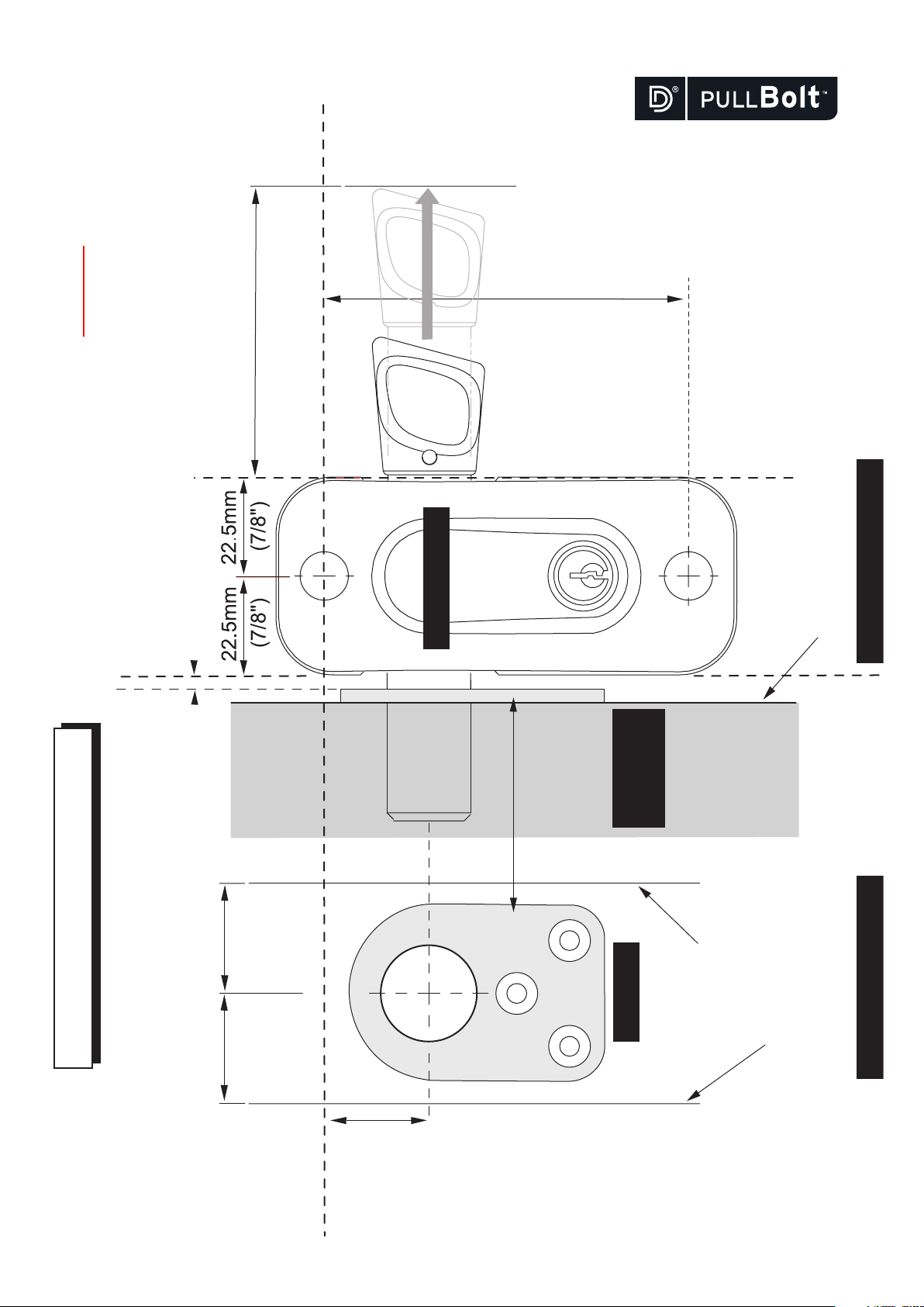
24mm
(15/16")
83mm (3.1/4")
LOCK BODY
KEEPER
FRONT TEMPLATESIDE TEMPLATE
Keeper in
side
position
WALL, FRAME
or POST
ALLOW 75mm (3") CLEARANCE
FOR HANDLE
25mm(1")
AND 13mm (1/2") MAXIMUM GAP
ALLOW 3 mm (1/8") MINIMUM GAP
FACE OF FRAME THAT
THE LOCK BODY IS
MOUNTED TO FOR A
LEFT-HAND OPENING
A
A
FACE OF POST THAT THE
SIDE-MOUNT KEEPER
IS MOUNTED TO
FACE OF FRAME
FOR A
RIGHT-HAND OPENING
D
E
D
E
25mm(1")
A
IMPORTANT: If printing these Instructions
from an electronic file (e.g. website download),
be sure to check that dimensions shown here
measure correctly, as differences in print-outs
may result in inaccurate template holes.
PULLBOLT SIDE-MOUNT MODEL
DRILLING TEMPLATE
PULLB000029PA •Instr_D&DPullBolt_SM (20/6/05)
Page 2

Changing from left- to right-hand fitting
1. Remove the key and
place the Lock Body
face down. Remove
the four corner screws
but DO NOT REMOVE
the two center screws
(shown at A).
Side-Mount model
2. Pick up the Lock Body
with both hands, being
careful to hold together
the front and back covers
(to prevent internal components moving). Turn over
the Lock Body and place
down on a at surface.
3. Lift the front cover and
place to one side. Lift the
bolt and ip it over as
shown, and place it back in
the cradle so that the pin
ts into the slot - either of
the two slots will work.
4. Replace the front cover and
re-t the four screws.
DO NOT use power screwdrivers;
use hand tools.
Optional: Blind Covers
Available separately
Steel washer
Plastic washer
Inside door
screw head dressing
Standard
Top view: Side-Mount model
Optional: Fixing Leg
Available separately
PULLB000028PA •Instr_D&DPullBolt_SM (14/12/11)
Page 3

FITTING INSTRUCTIONS SIDE-MOUNT MODEL
The D&D PullBolt™ is designed to provide added security to shop fronts, doors, frames and gates. The locking
mechanism is a “deadlock” design, meaning that it has to be locked in either the open or closed positions to
allow removal of the key. The PullBolt has a throw of 11/4” (32mm) and remains captured in the Lock Body
when locked in the open position. The PullBolt is designed to be mounted on the exterior of doors and gates, so
that the mounting-screw heads are concealed from manipulation.
Note: In the text below, the word “door” substitutes for “gate”.
Preparation: Before installing this D&D PullBolt™:
– ensure the maximum gap between the two mounting frames does not exceed
protrusion into the locking frame or ground of at least
3
/4” (19mm).
1
/2” (13mm). This will ensure a minimum bolt
– ensure there is at least 3” (75mm) of handle clearance to allow the bolt to retract when opening. Refer to the Drilling Template.
– ensure the handing is correct. The PullBolt is factory assembled to be mounted onto a left-hand opening door. To rotate the bolt to fit
right-hand opening see the instructions on the reverse side.
Tools required: Electric or cordless drill,
7
/16” dia. (11mm dia.), 7/8” dia. (22mm dia.) hole saw (or spade-bit for wood) and 1/8”
dia. (3.5mm dia.) drill bits, 6mm Allen key, square, hammer, centerpunch, pointed implement, pencil, adhesive tape (for temporarily
taping the template to the frame as required).
Installation procedure:
1. Determine the position on the door where you intend mounting the PullBolt, and, with the pencil, mark a fine, level centerline
across the face of the frame. This will be centerline ‘A’. Use the square to mark this centreline around to the side of the frame - and
then around to the rear of the frame. This is to ensure correct alignment of all drilled holes.
2. Transfer the line A across to the Wall Frame or Post. Mark a point
face (see ‘KEEPER’ on the drilling template). This is the center of the PullBolt hole. Centerpunch this point and drill a
dia.) hole to a maximum depth of 1
1
/4” (32mm).
15
/16” (24mm) down from this line and 1” (25mm) in from the
7
/8” dia. (22mm
3. Align the Keeper with this hole and mount it using the three screws provided.
4. Unlock the ‘LOCK BODY’ and fully retract the PullBolt handle. Place the Lock Body against the frame leaving a minimum gap of
1
/8” (3mm) between the edge of the Lock Body and the face of the Keeper. Ensure the door can open without any interference. Mark a
vertical “positioning line” on the frame using the outer edge of the Lock Body as a guide. Reproduce a corresponding line on the rear
face of the door frame by measuring.
5. Fold the template along line ‘D’ for left-hand mounting (or along line ‘E’ for right-hand mounting). Align the folded template line
with both the front positioning line and centerline ‘A’. Mark the two center points through the template using a pointed instrument,
then centerpunch these points. Now repeat this action at the rear positioning line using line ‘E’ (or line ‘D’ for left-hand mounting). This
ensures accurate, level drilling through the door section.
6. Drill holes of
7
/16” dia. (11mm dia.) through the frame - from both sides - in the places marked. (Smaller pilot holes may assist
drilling accuracy.)
7. Place the washers under the head of the M10 mounting screws and insert the screws into the rear drilled holes. A maximum thread
protrusion of
distributor for longer screws if required, or cut to
7
/8” (22mm) from the front of the door section and a minimum thread protrusion of 3/8” (10mm) applies. Contact your
3
/4” (19mm) if too long.
8. Take the 6mm Allen key and secure the mounting screws firmly into the Lock Body and Keeper.
Check to ensure that the PullBolt locks securely and that there is no interference when opening the door.
The D&D PullBolt™ is now ready for use.
MAINTENANCE: Lubricate the D&D PullBolt™ using only graphite powder. DO NOT use oil or grease.
For a downloadable Adobe Acrobat (.PDF) version of our Limited LIFETIME WARRANTY,
go to our website at www.ddtechglobal.com
AUSTRALIA: Unit 6, 4-6 Aquatic Dr, Frenchs Forest NSW 2086
USA: 7731 Woodwind Drive, Huntington Beach, CA 92647
www.ddtechglobal.com
PULLB000028PA •Instr_D&DPullBolt_SM (14/12/11)
 Loading...