

Page 1
Magna•Latch
®
Magna•Latch
®
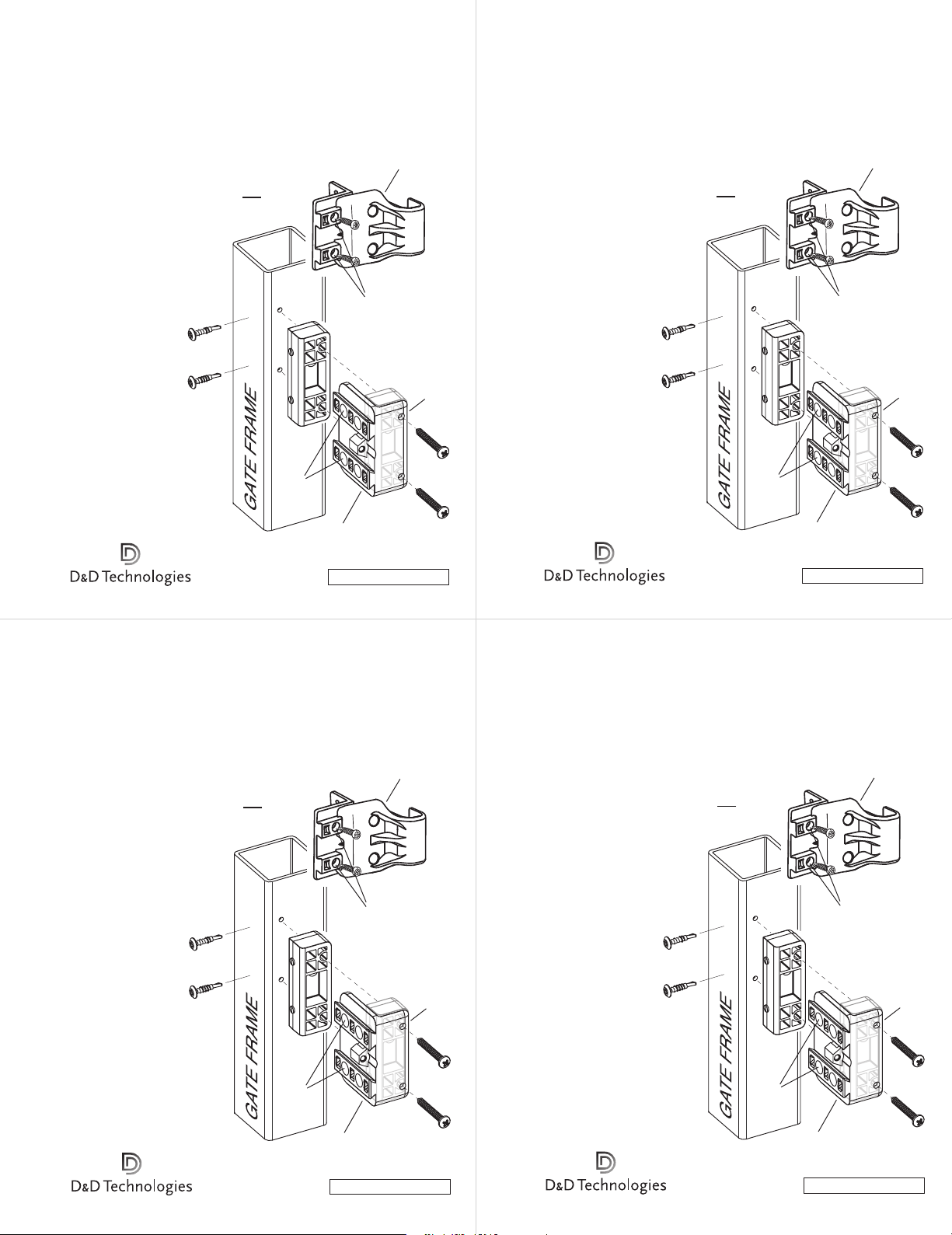
2” GATE GAP SPACER
The Magna•Latch® comes standard with a gate gap variance of
this spacer behind the Striker Mounting Plate to ensure
proper latch installation and operation.
1. Place the Striker Mounting Plate at the desired
height on the gate. Mark the two holes on the
of the gate with a pencil through the side-fixing leg.
Pre-drill the two holes using an
2. Place the 2" Gate Gap Spacer behind
the Striker Mounting Plate [B] up against
the side-fixing leg so that the screw holes
on both line up (see the dashed line
between A
mounting plate and gap spacer
against the corner of the gate frame.
3. Secure the two components
together and to the gate frame
using the two 1
4. Unwind the (obscured) adjustor screw
“G” in the Striker Housing enough to
expose the two holes [F1]. Fix the two
remaining self-drilling screws [D] to the
face of the Striker Mounting Plate.
Readjust the adjustor screw until the latch
functions smoothly.
3
/8" to 17/16". For larger gaps of 11/2"–2", install
Rear adjustor
screw (obscured)
side
11
/64" drill bit.
1
1
& A2). Place both the
D
5
/8" self-tapping screws [C].
2
F
www.ddtechglobal.com
MLINSTR0020PA
7731 Woodwind Drive, Huntington Beach, CA 92647. Tel (800) 716-0888.
F
1
A
2
A
B
STRIKER
MOUNTING PLATE
•instr_ddtech_23/2/06
G
STRIKER
HOUSING
Side
fixing
leg
C
2” GATE GAP SPACER
The Magna•Latch® comes standard with a gate gap variance of
this spacer behind the Striker Mounting Plate to ensure
proper latch installation and operation.
1. Place the Striker Mounting Plate at the desired
height on the gate. Mark the two holes on the side
of the gate with a pencil through the side-fixing leg.
Pre-drill the two holes using an
2. Place the 2" Gate Gap Spacer behind
the Striker Mounting Plate [B] up against
the side-fixing leg so that the screw holes
on both line up (see the dashed line
between A
mounting plate and gap spacer
against the corner of the gate frame.
3. Secure the two components
together and to the gate frame
using the two 1
4. Unwind the (obscured) adjustor screw
“G” in the Striker Housing enough to
expose the two holes [F1]. Fix the two
remaining self-drilling screws [D] to the
face of the Striker Mounting Plate.
Readjust the adjustor screw until the latch
functions smoothly.
3
/8" to 17/16". For larger gaps of 11/2"–2", install
Rear adjustor
screw (obscured)
11
/64" drill bit.
1
1
& A2). Place both the
D
5
/8" self-tapping screws [C].
2
F
www.ddtechglobal.com
MLINSTR0020PA
7731 Woodwind Drive, Huntington Beach, CA 92647. Tel (800) 716-0888.
F
1
A
2
A
B
STRIKER
MOUNTING PLATE
•instr_ddtech_23/2/06
G
STRIKER
HOUSING
Side
fixing
leg
C
Magna•Latch
®
2” GATE GAP SPACER
The Magna•Latch® comes standard with a gate gap variance of
this spacer behind the Striker Mounting Plate to ensure
proper latch installation and operation.
1. Place the Striker Mounting Plate at the desired
height on the gate. Mark the two holes on the side
of the gate with a pencil through the side-fixing leg.
Pre-drill the two holes using an
2. Place the 2" Gate Gap Spacer behind
the Striker Mounting Plate [B] up against
the side-fixing leg so that the screw holes
on both line up (see the dashed line
between A1 & A2). Place both the
mounting plate and gap spacer
against the corner of the gate frame.
3. Secure the two components
together and to the gate frame
using the two 1
4. Unwind the (obscured) adjustor screw
“G” in the Striker Housing enough to
expose the two holes [F1]. Fix the two
remaining self-drilling screws [D] to the
face of the Striker Mounting Plate.
Readjust the adjustor screw until the latch
functions smoothly.
3
/8" to 17/16". For larger gaps of 11/2"–2", install
Rear adjustor
screw (obscured)
11
/64" drill bit.
1
F
1
A
D
A
5
/8" self-tapping screws [C].
2
F
www.ddtechglobal.com
MLINSTR0020PA
7731 Woodwind Drive, Huntington Beach, CA 92647. Tel (800) 716-0888.
B
STRIKER
MOUNTING PLATE
•instr_ddtech_23/2/06
G
STRIKER
HOUSING
2
Side
fixing
leg
C
Magna•Latch
®
2” GATE GAP SPACER
The Magna•Latch® comes standard with a gate gap variance of
this spacer behind the Striker Mounting Plate to ensure
proper latch installation and operation.
1. Place the Striker Mounting Plate at the desired
height on the gate. Mark the two holes on the side
of the gate with a pencil through the side-fixing leg.
Pre-drill the two holes using an
2. Place the 2" Gate Gap Spacer behind
the Striker Mounting Plate [B] up against
the side-fixing leg so that the screw holes
on both line up (see the dashed line
between A1 & A2). Place both the
mounting plate and gap spacer
against the corner of the gate frame.
3. Secure the two components
together and to the gate frame
using the two 1
4. Unwind the (obscured) adjustor screw
“G” in the Striker Housing enough to
expose the two holes [F1]. Fix the two
remaining self-drilling screws [D] to the
face of the Striker Mounting Plate.
Readjust the adjustor screw until the latch
functions smoothly.
3
/8" to 17/16". For larger gaps of 11/2"–2", install
Rear adjustor
screw (obscured)
11
/64" drill bit.
1
F
1
A
D
5
/8" self-tapping screws [C].
2
F
www.ddtechglobal.com
MLINSTR0020PA
7731 Woodwind Drive, Huntington Beach, CA 92647. Tel (800) 716-0888.
B
STRIKER
MOUNTING PLATE
•instr_ddtech_23/2/06
A
2
G
STRIKER
HOUSING
Side
fixing
leg
C
Page 2
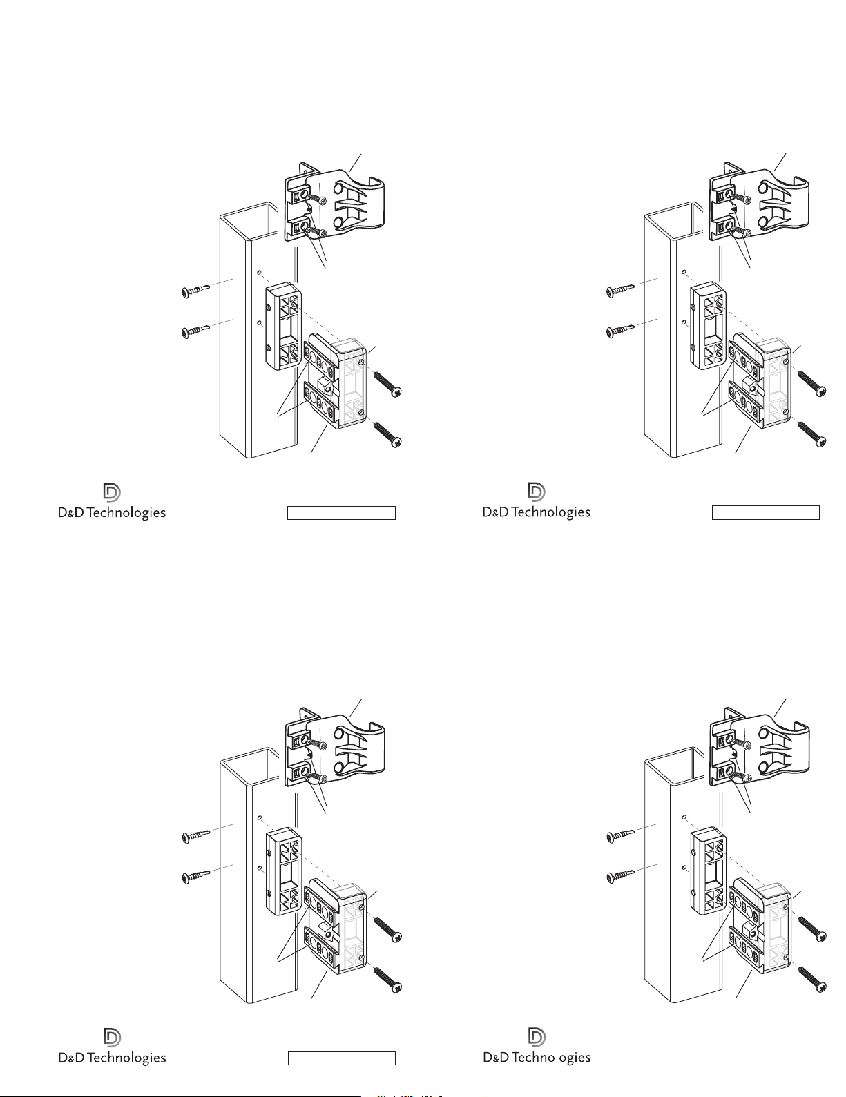
ESPACIADOR DE 2” PARA DIFERENCIA
ESPACIADOR DE 2” PARA DIFERENCIA
DE DISTANCIA DE PUERTA O PORTÓN
Magna•Latch® se presenta estándar con una diferencia de
distancia de puerta de
1
1
/2"–2", instalar este espaciador detrás de la lámina de
montaje de la cerradura hembra para garantizar la instalación
y operación adecuada del cerrojo.
1. Colocar la lámina de montaje de la cerradura hembra a la altura
deseada sobre la puerta o portón. Marcar los dos agujeros sobre la
parte lateral de la puerta usando un lápiz y a través de la pata del
lado de fijación. Pre-perforar dos agujeros usando
una mecha para taladro de
2. Colocar el espaciador de 2" para diferencia de
distancia de puerta detrás de la lámina de montaje
de la cerradura hembra [B] contra la pata lateral de
fijación de manera que los agujeros de los tornillos
en ambos se encuentren alineados (ver la
línea entrecortada entre A1 y A2 ). Colocar
la lámina de montaje y el espaciador de distancia
contra la esquina del marco de la puerta.
3. Fijar las dos partes juntas y al marco de
la puerta usando los dos tornillos autoroscantes
5
de 1
/8" [C].
4. Aflojar el tornillo (tapado) regulador “G” en la
caja de la cerradura hembra lo suficiente como para
dejar expuestos los dos agujeros [F1 ]. Fijar los dos
tornillos autoroscantes restantes [D] a la cara de la
lámina de montaje de la cerradura hembra. Volver
a ajustar el regulador hasta que el cerrojo funcione
suavemente.
7731 Woodwind Drive, Huntington Beach, CA 92647. Tel (800) 716-0888.
3
/8" a 17/16". Para espacios mayores de
11
/64".
A
D
2
F
PATA LATERAL DE FIJACIÓN
www.ddtechglobal.com
MLINSTR0020PA
B
LÁMINA DE MONTAJE DE
LA CERRADURA HEMBRA
•instr_ddtech_23/2/06
Tornillo regulador
trasero (tapado)
1
F
1
A
CAJA DE LA
CERRADURA
HEMBRA
2
G
Pata
lateral
de
fijación
C
DE DISTANCIA DE PUERTA O PORTÓN
Magna•Latch® se presenta estándar con una diferencia de
distancia de puerta de 3/8" a 17/16". Para espacios mayores de
1
/2"–2", instalar este espaciador detrás de la lámina de
1
montaje de la cerradura hembra para garantizar la instalación
y operación adecuada del cerrojo.
1. Colocar la lámina de montaje de la cerradura hembra a la altura
deseada sobre la puerta o portón. Marcar los dos agujeros sobre la
parte lateral de la puerta usando un lápiz y a través de la pata del
lado de fijación. Pre-perforar dos agujeros usando
una mecha para taladro de
2. Colocar el espaciador de 2" para diferencia de
distancia de puerta detrás de la lámina de montaje
de la cerradura hembra [B] contra la pata lateral de
fijación de manera que los agujeros de los tornillos
en ambos se encuentren alineados (ver la
línea entrecortada entre A1 y A2 ). Colocar
la lámina de montaje y el espaciador de distancia
contra la esquina del marco de la puerta.
3. Fijar las dos partes juntas y al marco de
la puerta usando los dos tornillos autoroscantes
5
de 1
/8" [C].
4. Aflojar el tornillo (tapado) regulador “G” en la
caja de la cerradura hembra lo suficiente como para
dejar expuestos los dos agujeros [F1 ]. Fijar los dos
tornillos autoroscantes restantes [D] a la cara de la
lámina de montaje de la cerradura hembra. Volver
a ajustar el regulador hasta que el cerrojo funcione
suavemente.
7731 Woodwind Drive, Huntington Beach, CA 92647. Tel (800) 716-0888.
11
/64".
D
F
PATA LATERAL DE FIJACIÓN
www.ddtechglobal.com
MLINSTR0020PA
2
•instr_ddtech_23/2/06
Tornillo regulador
trasero (tapado)
CAJA DE LA
CERRADURA
HEMBRA
1
F
1
A
2
A
B
LÁMINA DE MONTAJE DE
LA CERRADURA HEMBRA
G
Pata
lateral
de
fijación
C
ESPACIADOR DE 2” PARA DIFERENCIA
DE DISTANCIA DE PUERTA O PORTÓN
Magna•Latch® se presenta estándar con una diferencia de
distancia de puerta de
11/2"–2", instalar este espaciador detrás de la lámina de
montaje de la cerradura hembra para garantizar la instalación
y operación adecuada del cerrojo.
1. Colocar la lámina de montaje de la cerradura hembra a la altura
deseada sobre la puerta o portón. Marcar los dos agujeros sobre la
parte lateral de la puerta usando un lápiz y a través de la pata del
lado de fijación. Pre-perforar dos agujeros usando
una mecha para taladro de
2. Colocar el espaciador de 2" para diferencia de
distancia de puerta detrás de la lámina de montaje
de la cerradura hembra [B] contra la pata lateral de
fijación de manera que los agujeros de los tornillos
en ambos se encuentren alineados (ver la
línea entrecortada entre A1 y A2 ). Colocar
la lámina de montaje y el espaciador de distancia
contra la esquina del marco de la puerta.
3. Fijar las dos partes juntas y al marco de
la puerta usando los dos tornillos autoroscantes
5
de 1
/8" [C].
4. Aflojar el tornillo (tapado) regulador “G” en la
caja de la cerradura hembra lo suficiente como para
dejar expuestos los dos agujeros [F1 ]. Fijar los dos
tornillos autoroscantes restantes [D] a la cara de la
lámina de montaje de la cerradura hembra. Volver
a ajustar el regulador hasta que el cerrojo funcione
suavemente.
7731 Woodwind Drive, Huntington Beach, CA 92647. Tel (800) 716-0888.
3
/8" a 17/16". Para espacios mayores de
11
/64".
A
D
2
F
PATA LATERAL DE FIJACIÓN
www.ddtechglobal.com
MLINSTR0020PA
B
LÁMINA DE MONTAJE DE
LA CERRADURA HEMBRA
•instr_ddtech_23/2/06
Tornillo regulador
trasero (tapado)
1
F
1
A
CAJA DE LA
CERRADURA
HEMBRA
2
G
Pata
lateral
de
fijación
C
ESPACIADOR DE 2” PARA DIFERENCIA
DE DISTANCIA DE PUERTA O PORTÓN
Magna•Latch® se presenta estándar con una diferencia de
distancia de puerta de 3/8" a 17/16". Para espacios mayores de
1
/2"–2", instalar este espaciador detrás de la lámina de
1
montaje de la cerradura hembra para garantizar la instalación
y operación adecuada del cerrojo.
1. Colocar la lámina de montaje de la cerradura hembra a la altura
deseada sobre la puerta o portón. Marcar los dos agujeros sobre la
parte lateral de la puerta usando un lápiz y a través de la pata del
lado de fijación. Pre-perforar dos agujeros usando
una mecha para taladro de
2. Colocar el espaciador de 2" para diferencia de
distancia de puerta detrás de la lámina de montaje
de la cerradura hembra [B] contra la pata lateral de
fijación de manera que los agujeros de los tornillos
en ambos se encuentren alineados (ver la
línea entrecortada entre A1 y A2 ). Colocar
la lámina de montaje y el espaciador de distancia
contra la esquina del marco de la puerta.
3. Fijar las dos partes juntas y al marco de
la puerta usando los dos tornillos autoroscantes
5
de 1
/8" [C].
4. Aflojar el tornillo (tapado) regulador “G” en la
caja de la cerradura hembra lo suficiente como para
dejar expuestos los dos agujeros [F1 ]. Fijar los dos
tornillos autoroscantes restantes [D] a la cara de la
lámina de montaje de la cerradura hembra. Volver
a ajustar el regulador hasta que el cerrojo funcione
suavemente.
7731 Woodwind Drive, Huntington Beach, CA 92647. Tel (800) 716-0888.
11
/64".
D
F
PATA LATERAL DE FIJACIÓN
www.ddtechglobal.com
MLINSTR0020PA
2
•instr_ddtech_23/2/06
Tornillo regulador
trasero (tapado)
CAJA DE LA
CERRADURA
HEMBRA
1
F
1
A
2
A
B
LÁMINA DE MONTAJE DE
LA CERRADURA HEMBRA
G
Pata
lateral
de
fijación
C
 Loading...