

Page 1
®
™
KwikFit
Installation Instructions
for KFS & KFP models
Congratulations on your purchase of D&D Technologies’ Kwik-Fit hinges. We are confident that these hinges will provide you with a
lifetime of reliable gate operation (see Warranty & Limitation of Liability below).
Note: Use 12-gauge screws or bolts only. Do not use countersinking screws or attempt to countersink the hinges. Consult your local
hardware store for fastener options.
Tools required: Pencil, electric or cordless drill, 11/64” [4.5mm] drill bit (for 12 gauge screws/bolts), #2 Phillips-head driver bit.
Maintenance Requirements:
Note: The hinges will operate properly, and warranty is valid, only if installed in accordance with the instructions and
specifications shown herein.
• Use only two (2) Kwik-Fit hinges on any one gate.
• Remove all existing hinges and self-closing devices.
• Ensure the gate does not swing through the line of the fence (180˚).
Use a “gate stop” or a latch (with striker) to prevent this.
• Do not lubricate these hinges with petroleum-based lubricants
• Ensure the hinges are kept free of sand, ice and other
debris that could impair effective operation.
• Do not disassemble these hinges at any time.
• Do not paint or apply any additional finishes to the hinges.
• Never remove hinges from gate while under spring tension.
at any time. Use only powdered spray graphite.
• Do not physically cut, drill, countersink, machine or grind any part of the hinges.
• If through-bolts are used, remove excess bolt by cutting, grinding and/or filing.
Maximum Weight of Gate Maximum Gate Dimensions
KFS: 45 lb [20 kg] * 5’H x 3’W (1524x915mm)
KFP: 55 lb [25 kg] * 5’H x 3’W (1524x915mm)
* Always space the hinges as far apart from each other as possible, for maximum holding strength.
Procedure 1:
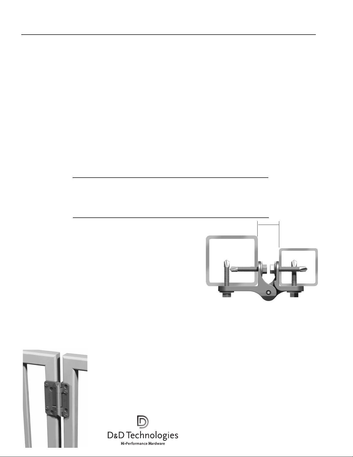
Note: The gap between the fence post and gate frame must be 3/4” (19mm).
Determine the desired location of the hinges on the fence post and gate frame.
The larger side of the hinge should be fixed to the fence post and the smaller side
to the gate frame. Remember to space the hinges as far apart as possible for
maximum holding strength. Mark the holes for drilling using the pencil.
Procedure 2:
Pre-drill the holes on the gate frame first using the 11/64” [4.5mm] drill bit.
Install both hinges on the gate frame. Use a low clutch setting on the drill to
ensure you do not strip the screws/bolts.
Procedure 3:
Re-position the gate onto the fence post to ensure the holes marked on the fence
post are in the correct position. If not, re-mark the holes on the post using the
pencil. Pre-drill the holes using the 11/64” [4.5mm] drill bit. Install both hinges.
The gate is now ready for use.
WARRANTY & LIMITATION OF LIABILITY
D&D Technologiesʼ (“D&D”) products are warranted to be free of defects in materials and workmanship to the original
purchaser for as long as he/she owns the product. This product will operate properly, and warranty is valid, only if installed
in accordance with the instructions and specications shown. If a structural defect appears, the original purchaser may return
the item, freight prepaid, together with proof of purchase to D&D or its approved international agents. D&D or its agent will,
at their discretion, repair or replace the defective item or part without charge to the purchaser.
THIS WARRANTY SHALL NOT APPLY WHEN the product has been tampered with, when repairs or attempted repairs have
been made by unauthorized persons, where the item has been subjected to misuse, abuse, accident or damage in transit, or
where the installer has not followed the instructions set out during installation, operations, or Maintenance Requirements.
IN NO EVENT SHALL THE COMPANY BE LIABLE FOR ANY INCIDENTAL OR CONSEQUENTIAL DAMAGES. No warranty is given other
than that set out above. No other express or implied warranties (including statutory warranties) apply, other than warranties
which may not be legally excluded.
3
/4”
(19mm)
Fence Post
Gate Frame
NOTE: Kwik-Fit hinges are intended for post mounting
only. For mounting to walls where there is no room for a
fence post, use D&D’s “Multi-Adjust” MFA model.
AUSTRALIA: Unit 6, 4-6 Aquatic Dr, Frenchs Forest NSW 2086
USA: 7731 Woodwind Drive, Huntington Beach, CA 92647
EUROPE: Vondellaan 58, 3521 GH Utrecht, The Netherlands.
www.ddtechglobal.com
•Instructs KF 28/10/06 KFINSTR0000PA
Page 2
®
™
KwikFit
Instrucciones para la instalación
de los modelos KFS y KFP
Le felicitamos por haber comprado las bisagras Kwik-Fit de D&D Technologies. Estamos seguros de que estas bisagras le ofrecerán una
operación confiable de su portón durante toda la vida. (ver la Garantía limitada de uso abajo descrita).
Observación: Usar únicamente tornillos o pernos calibre 12. No usar tornillos avellanados ni tratar de avellanar las bisagras.
Consultar con su ferretería local sobre las opciones de los sujetadores.
Herramientas necesarias: Lápiz, taladro eléctrico o inalámbrico, broca o mecha de 11/64” [4.5mm] (para tornillos o pernos calibre 12 ),
mecha #2 Phillips.
Requisitos de mantenimiento:
Observación: Las bisagras funcionarán correctamente, y la garantía será válida,
únicamente si la instalación se lleva a cabo de acuerdo con las instrucciones y
especificaciones aquí contenidas.
• Usar únicamente dos (2) bisagras Kwik-Fit por puerta.
• Retirar cualquier otro tipo de bisagra existente y aparatos de autocierre.
• Asegurarse de que la puerta no se balancee a través de la línea de la cerca. Usar
un tope para puertas o cerrojo (con cerradura hembra) para evitar que esto ocurra.
• No lubricar estas bisagras con lubricantes a base de petróleo, en ningún
momento. Usar únicamente grafito en polvo en aerosol.
• Si se usan tuercas retirar el excedente cortando o
esmerilando cualquier parte de las bisagras.
• Asegurarse de mantener las bisagras sin arena, hielo
ni ningún otro tipo de escombro que podría dificultar la
efectividad de la operación.
• No desarmar estas bisagras en ningún momento.
• No pintar ni aplicar acabados sobre estas bisagras.
• No retirar nunca las bisagras de la puerta mientras se
encuentre bajo la tensión del resorte.
• No cortar, perforar, hacer un avellanado, usar una máquina ni esmerilar
físicamente ninguna parte de las hojas de las bisagras.
Procedimiento 1:
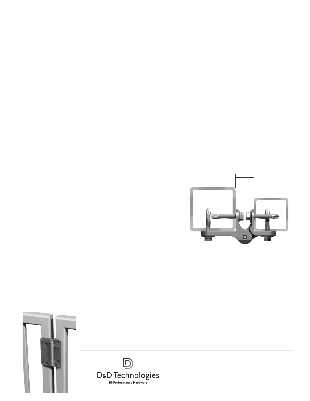
Observación: El espacio entre el soporte de la cerca y el marco de la puerta debe ser
de 3/4” (19mm). Determinar el sitio deseado de las bisagras en el poste de la cerca y
el marco de la puerta. El lado más grande de la bisagra deberá estar fijado al soporte
de la cerca y el lado pequeño al marco de la puerta. Recuerde espaciar las bisagras
lo máximo posible entre una y otra para lograr un máximo de resistencia. Marcar los
agujeros para taladrar usando un lápiz.
Procedimiento 2:
Pretaladrar los agujeros en el marco de la puerta usando una mecha para taladro de
11
/64” [4.5mm]. In¬stalar ambas bisagras en el marco de la puerta. Usar un em-
brague bajo del taladro para evitar desmontar los tornillos o pernos.
Procedimiento 3:
Reposicionar la puerta en el poste de la cerca asegurándose de que los agujeros marcados en el poste de la cerca se encuentren en la posición correcta. De lo contrario,
remarcar los agujeros en el poste usando un lápiz. Pretaladrar los agujeros usando
una mecha para taladro de 11/64” [4.5mm]. Instalar ambas bisagras. Ahora la puerta
está lista para usar.
Peso máximo de la puerta Dimensiones máximas de la puerta
KFS: 45 lb [20 kg] * 5’H x 3’W (1524x915mm)
KFP: 55 lb [25 kg] * 5’H x 3’W (1524x915mm)
* Espaciar siempre las bisagras lo máximo posible entre una y otra para lograr un máximo de resistencia.
3
/4”
(19mm)
Fence Post
Gate Frame
OBSERVACIÓN: Las bisagras Kwik-Fit están
fabricadas para instalarse únicamente en los postes.
Para la instalación en paredes donde no hay lugar
para un poste para cerca, usar el modelo
“Multi-Adjust” MFA.
AUSTRALIA: Unit 6, 4-6 Aquatic Dr, Frenchs Forest NSW 2086
USA: 7731 Woodwind Drive, Huntington Beach, CA 92647
EUROPE: Vondellaan 58, 3521 GH Utrecht, The Netherlands.
•Instructs KF 28/10/06 KFINSTR0000PA
www.ddtechglobal.com
 Loading...