


DDTi

REFERENCE MANUAL


TABLE OF CONTENTS
INTRODUCTION ...................................................................... 1
FRONT PANEL OVERVIEW .................................................... 2
REAR PANEL OVERVIEW ...................................................... 2
HOOKUP DIAGRAM ................................................................ 3
COMPUTER INSTALLATION .................................................. 4
GETTING STARTED – USING KITS ....................................... 6
SAVING KITS ....................................................................... 6
PROGRAM CHANGE MESSAGES ......................................... 7
EDITING KITS .......................................................................... 8
TRIGGER MIDI CHANNEL .................................................. 8
TRIGGER MIDI NOTE ......................................................... 9
SETTING GLOBAL PARAMETERS ...................................... 10
GAIN ................................................................................... 11
VELOCITY CURVE ............................................................ 12
THRESHOLD ..................................................................... 13
X-TALK (CROSSTALK) ...................................................... 14
RETRIGGER ...................................................................... 15
TRIGGER TYPE ................................................................. 16
USING HI-HAT PEDALS ........................................................ 17
EDITING HI-HAT PEDAL PARAMETERS ......................... 17
SENDING MESSAGES .......................................................... 18
ALL NOTES OFF................................................................ 18
RETURN TO DEFAULT VALUE ........................................ 18
FACTORY RESET ............................................................. 18
MIDI SYSEX TRANSFERS ................................................ 18
DEFAULT SETTINGS FOR THE DDTi .............................. 19
OTHER APPLICATIONS OF THE DDTi ................................ 20
DDTi KIT PRESETS ............................................................... 21
DDTi DEFAULT GLOBAL PARAMETERS ........................... 22
TROUBLESHOOTING ........................................................... 23
MIDI IMPLEMENTATION ....................................................... 26


1
INTRODUCTION
Congratulations on your purchase of the Ddrum DDTi USB/MIDI Percussion
Interface. With the Ddrum DDTi, you can connect your favorite acoustic drum
triggers or electronic percussion pads and control sounds on external drum
machines, modules or software devices. Here at Ddrum, we take pride in building
electronic instruments and controllers for the modern musician. The DDTi allows
you to explore new avenues of sonic possibilities with an intuitive percussion
interface. You no longer have to worry about feeling disembodied from your music
experience. The DDTi offers an ideal approach to controlling and sequencing
rhythm content. We hope that you enjoy this great product!
Ddrum USA

2
FRONT PANEL OVERVIEW
1. FUNCTION UP/DOWN – These buttons are used to select through different functions on the DDTi
2. VALUE UP/DOWN – These buttons are used to cycle through kits and parameters for the different
functions.
3. FUNCTION LEDs – Each function on the DDTi is paired with a corresponding LED on the panel.
These LED will reflect which function is currently being selected.
4. LED SCREEN – The LED screen displays information about the state of the DDTi. The screen also
features a small “Activity” LED which will light up each time a trigger generates a Note On message, as
well as a “Trig B” LED which will light up when the secondary zone (ring) of a dual-zone trigger
generates a Note On message.
REAR PANEL OVERVIEW
1. Power Button – This button functions as an AC/USB power switch. If the button is in the IN position
(AC), the unit will draw power from the connected AC power adapter. If the button is in the OUT
position (USB), the unit will draw power from the USB connection to your computer.
2. USB Port – The USB port is used to transmit MIDI data between the DDTi and a computer. This port
may also be used to power the unit if the power button is in the OUT position (USB). However, if your
computer’s USB port does not provide sufficient power to the DDTi, please use the included AC
adapter to power the unit.
3. Power Adapter Input – If you do not wish to power the unit through the USB port, please use the
included AC power adapter to connect the DDTi to a power source and press the power button so it is
in the IN position (AC) – the unit will draw power from the power adapter.
4. Power Adapter Restraint – You can secure the power adapter cord to this restraint to prevent
accidental unplugging.
5. MIDI OUT – Use a five-pin MIDI cable to connect this output to the MIDI IN of an external device, such
as a drum machine, synthesizer or sound module.
6. 10 TRS Trigger Inputs – Please connect your trigger sources to these ten ¼” TRS inputs. You will
notice that some of the inputs are marked. If you would like to take advantage of certain preprogrammed presets, such as the GM or BFD Lite drum mappings, please follow these markings to
connect your triggers.
7. HI-HAT Input – Please connect your hi-hat pedal to this input.
8. INC/DEC pedal input – Please connect a dual footswitch button to this input. Using this footswitch
input allows you to remotely increment and decrement values from your dual footswitch.
9. KENSINGTON LOCK – You may use this Kensington lock slot to secure the unit to a table or surface.

3
HOOKUP DIAGRAM
Please study the following diagram to connect your DDTi.
POWER ADAPTER
(OPTIONAL)
ATTACH 2 BUTTON FOOTSWITCH HERE
ATTACH ADDITIONAL TRIGGERS HERE
TO EXTERNAL MIDI MODULE
TO COMPUTER
1. Before turning on the DDTi, connect all triggers, pads, footswitches, MIDI devices and external
modules as shown above. If you would like to use the DDTi with a computer, connect a USB
cord from the DDTi to your computer’s USB port.
2. Connect a power source to the DDTi. You have two options for powering the DDTi:
a. Connect the DDTi to a computer’s USB port – the computer’s USB bus will provide
power.
b. Connect an optional 9V AC power adapter to the DDTi.
3. Use the power switch on the rear panel of the DDTi to turn it on.
Important: Please use the appropriate cables to connect your triggers to the DDTi. For single
zone triggers, please use TS cables to connect them to the DDTi. If using dual-zone triggers,
please make sure that you are using TRS cables. Using TS cables to connect dual-zone triggers
to the DDTi will only allow you to use the primary zone (tip) of the drum.

4
COMPUTER INSTALLATION
The DDTi is a Plug-and-Play device so there is no driver or special software
installation required. When the DDTi is connected to a computer, it will automatically
be recognized as an available USB device.
How to connect and use the DDTi with a software application:
1. Connect a USB cord from the USB port of the DDTi to the USB port of your
computer.
When the DDTi is connected to a computer using a USB cord, the
computer’s USB bus will provide power to the unit. If you would like to use
an alternate power source, plug in a 9v AC power adapter.
2. Press the power switch on the back panel of the DDTi. The display will turn
on to let you know that the DDTi is on.
!
Tip
It is a good idea to connect and turn on the DDTi before starting
any software applications with which you intend to use the DDTi.
Otherwise the software program will not recognize the DDTi as
being connected.
3. Open up your software application.
4. Next, select the DDTi as a MIDI input device. Usually, this is done in the
Preferences menu of the software application.
If you are using Windows XP, you will notice that the DDTi may appear as
‘USB Audio Device’ or ‘USB Audio Device (Emulated)’. Please make sure
that this MIDI input is enabled and active.
(Cubase LE example shown on
left. You may access the MIDI
inputs by going to Devices |
Device Setup and clicking on All
MIDI Inputs.)
5. Now the DDTi should be ready to use with the software application.
5
!
A Note About Audio Latency
Latency describes the time that it takes for your soundcard to
respond to a command. In other words, this is the time that it takes
for your computer to process incoming data (for example, MIDI
Note events) and output a sound. The lower your latency is, the
faster your computer will respond to commands and output sound.
Please make sure that your soundcard’s latency (or buffer) is set to
a low number so when you hit the pads on the DDTi, your
computer will output the sound promptly. Latency and buffering is
usually adjusted in your software’s Preferences menu. In general,
if latency is higher than about 15-20ms, you will start to notice a
significant delay between the time that you hit the pads and the
time that the sound comes out of your computer.
If you still experience too much latency or “lag” with your internal
soundcard audio drivers, you might want to download one of the
free and widely available ASIO (Audio Stream Input/Output) drivers
from the Internet. In general, ASIO drivers perform better and with
lower latency since they create a more efficient communication
between audio devices and software. You may download and
install the free ASIO4ALL driver (PC) by visiting www.asio4all.com.
(Only compatible with USB audio interfaces)
6
GETTING STARTED – USING KITS
What is a Kit?
A Kit, also known as a Preset, is a collection of parameters which describe
different configurations of the DDTi. These parameters include the MIDI
Note Numbers assigned to triggers, MIDI Channels on which the triggers
are sending information, as well as associated Program Change messages.
Using kits allows you to store and access different trigger setups and allows
you to address different hardware and software module configurations.
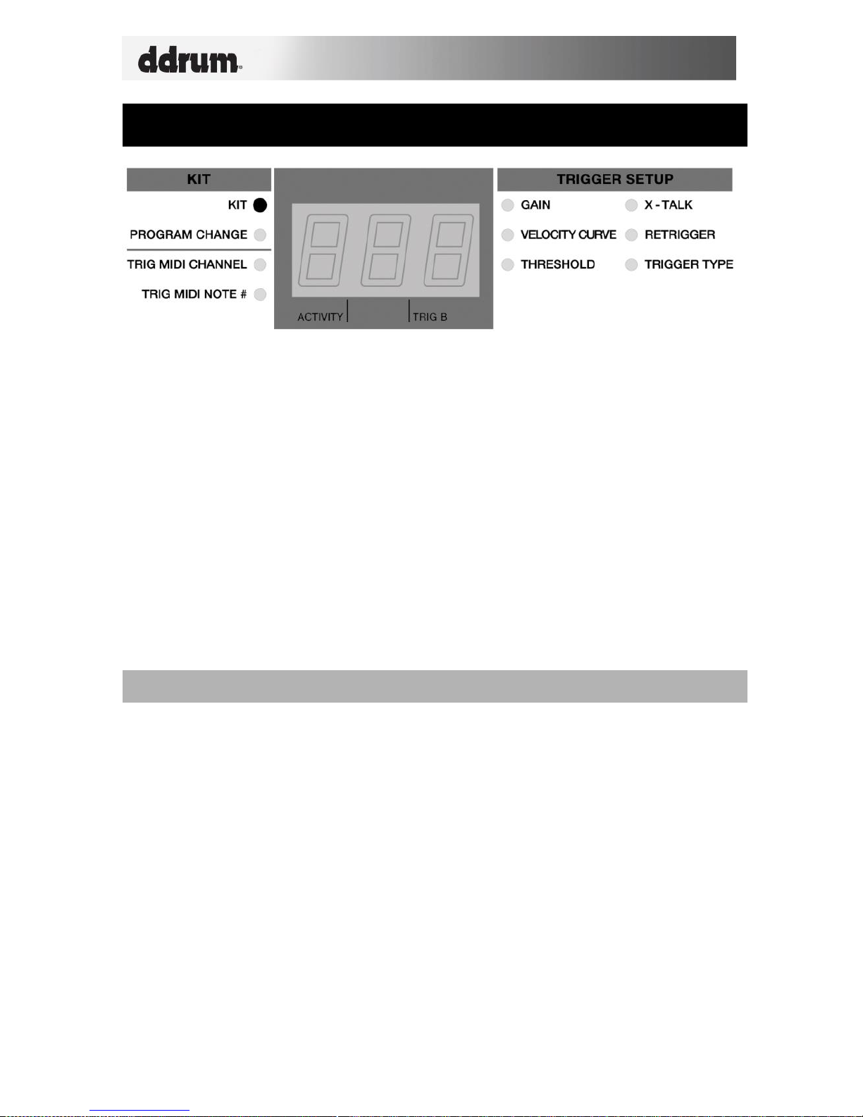
The DDTi automatically goes into Kit selection function when it is turned on. Notice
that the LED next to Kit is lit. If you are in a different function, you can always get to
the Kit selection function by using the function up/down buttons.
When in Kit selection function, you can use the value up/down buttons to select
different kits. The DDTi will automatically load the kits as you step through the
values. There are 21 available kits that you can load, modify and store.
SAVING KITS
If you have made changes to the selected kit (i.e. changed MIDI note numbers,
channels), you will notice that the LED next to Kit will begin blinking. This means
that there are changes which have not yet been saved. To save these changes,
please use the function up/down buttons to return to the Kit Function. This will
save the changes you have made to the current kit.
Alternatively, if you have made changes to the current kit but do not wish to save
them, press function down and value down buttons simultaneously. This will
cancel any changes made after the kit was loaded.
7
PROGRAM CHANGE MESSAGES
A Program Change, often referred to as a Patch Change, is a MIDI message used for
sending data to devices to cause them to change to a new program. This allows you
to tell a hardware or software device which sound to play. For example, if your DDTi
is controlling a rock drum kit in your DAW or on an external hardware device, using a
Program Change command allows you to easily switch to an electronic kit. Program
Change messages also give you the freedom to re-orchestrate MIDI content without
having to redo any MIDI note information.
Each kit on the DDTi can have an associated Program Change message (0-127).
This means that, effectively, you can have each kit on the DDTi address a different
set of sounds in your DAW or external MIDI device. By default, each kit on the DDTi
is set to “---“. A Program Change message of “---“ means that no Program Change
message will be sent when the kit is loaded.
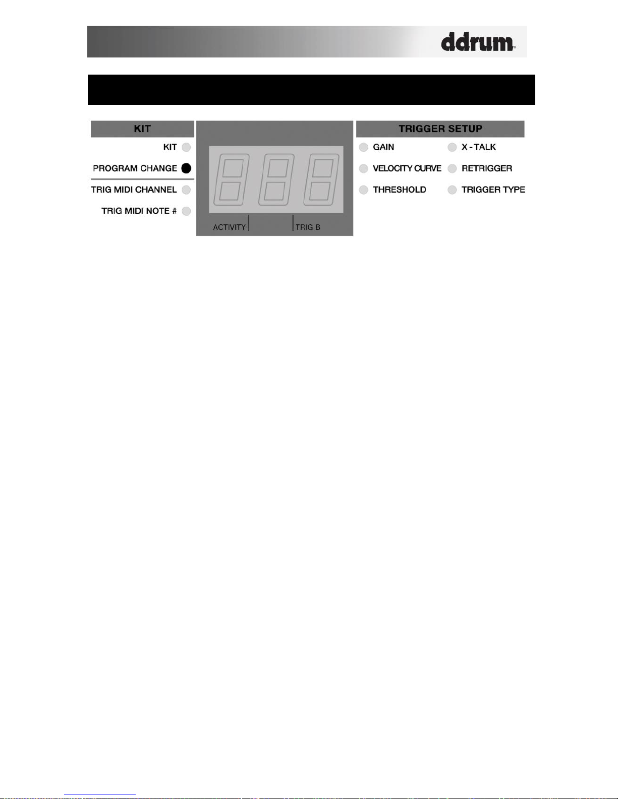
How to set a Program Change Message:
1. Use the function up/down buttons to select Program Change.
2. Select the desired Program Change message (0-127) using the value
up/down buttons to dial in the value. The Program message will be sent
automatically and will affect only that kit.
3. Subsequently, every time you load the kit the selected Program Change
message will be sent to your DAW or external MIDI device.
REMEMBER TO SAVE YOUR CHANGES BY GOING BACK TO KIT!
 Loading...