


dCS Elgar Plus
Stereo Digital to Analogue Converter
User Manual
Software Release 4.3x
September 2004
© dCS Ltd. 1999 - 2004 Price UK £17.50 / Euro 25.00
All rights reserved. No part of this publication may be reproduced, stored in or
introduced into a retrieval system, or transmitted in any form, or by any means
(electronic, mechanical, photocopying, recording or otherwise) without the prior
written permission of dCS
relation to this publication may be liable to criminal prosecution and civil claims
for damages.
1
. Any person who does any unauthorised act in
Information contained in this manual is subject to change without notice, and
whilst it is checked for accuracy, no liabilities can be accepted for errors.
1
dCS is Data Conversion Systems Ltd. Company registered in England No. 2072115.

dCS Elgar Plus User Manual Manual for Software Issue 4.3x
dCS Ltd September 2004
Manual filename: Elgar Manual v4.3x.doc Page 2 email: more@dcsltd.co.uk
English version web-site: www.dcsltd.co.uk

dCS Elgar Plus User Manual Manual for Software Issue 4.3x
dCS Ltd September 2004
PRODUCT OVERVIEW
The dCS Elgar Plus is derived from our award winning dCS Elgar, the world’s
first 24/96 and 24/192 audiophile D/A converter. Elgar Plus offers many
improvements over the standard Elgar, the most important being the ability to
handle DSD from IEEE 1394 or SDIF-2 interfaces, the ability to slave to a Word
Clock or act as a Master Clock, a digital output and a substantially expanded
Function Menu.
All dCS DACs feature our patented d CS Ring DAC technology. This unveils the
intricate low level musical detail that is dCS’ hallmark.
Elgar Plus will accept digital data at 44.1kS/s from your CD player and
interpolate the 16 bits, giving your CD collection a new lease of life. Elgar Plus
will also convert 24 bit 96kS/s data from DVD players, revealing the increased
depth and spaciousness inherent in the more complex source information. With
the current software version, Elgar Plus also has the ability to act as a master
clock for your transport, increasing the clocking precision of the overall system.
Units fitted with the IEEE 1394 interface option can convert DSD data (a single
bit data stream, sampled at 2.822MS/s) from a suitably equipped Upsampler or
SACD player to extra wide-band audio, taking advantage of the extended
bandwidth inherent in the DSD format.
All dCS DACs use the same digital processing engine running the same DSP
code. The extensive use of programmable logic makes dCS products extremely
flexible and easy to upgrade. You can load updated Elgar Plus software from a
dCS CD using a CD player, or dCS service agents can download software to the
SUC port, using a PC.
Manual filename: Elgar Manual v4.3x.doc Page 3 email: more@dcsltd.co.uk
English version web-site: www.dcsltd.co.uk

dCS Elgar Plus User Manual Manual for Software Issue 4.3x
dCS Ltd September 2004
CONTENTS
Product Overview..............................................................................................3
Contents.............................................................................................................4
About this Manual 7
What does the coloured text mean? 7
About Sample Rates x 7
Step-by-Step Guide ...........................................................................................8
Preliminaries 8
Step 1 – Selecting a Digital Input 9
Connecting to a Single AES or SPDIF source 9
Connecting to a Dual AES Source x 9
Connecting to an IEEE 1394 DSD Source 9
Connecting to an SDIF/DSD Source 9
Step 2 – Connecting the Analogue Outputs 11
Using a preamplifier x 11
Using a power amplifier directly x 11
Step 3 - Setting the Output Level 12
Step 4 - Using Elgar Plus in Master Mode 13
Other Settings 13
Typical Applications........................................................................................14
Using an Elgar Plus in Master Mode with Verdi 14
Using Elgar Plus and a 1394-Equipped Purcell with Verdi 15
Using Elgar Plus with a Standard Purcell and a CD Player 16
The Software – The Menu...............................................................................18
Using the Function Menu 19
Opening the Menu 19
Types of Menu Page 19
Closing the Menu 19
Menu Sequence 20
Filter – Anti-Imaging Filter Setting 20
Selecting a Filter x 20
MS – Master/Slave Operation 21
Setting to Master Mode x 21
Mute - Mute Fade Time 22
Fade – Fade Behaviour After Re-Lock 22
Dual AES – Dual AES Mode 23
Swap - Swap Channels 24
Disp - Default Display 24
Bal Mode - Balance Information Display 24
Global – Global/Local Volume 25
TimeOut – Menu Time Out Setting 25
PLL - PLL Tracking bandwidth 25
NAud - Non Audio Muting 26
Override Non-Audio Muting x 26
Disabling Non-Audio Muting x 26
Restoring Non-Audio Muting x 26
Ch.Check - Channel Check Test 27
Ph.Check - Phase Check Test 27
Burn In - Burn-In Signal Generation 28
Test - Display Test 28
Issue – Software Issue State 29
Temp – Unit Internal Temperature 29
Serial – Unit Serial Number 29
Contact - Contact information 29
Manual filename: Elgar Manual v4.3x.doc Page 4 email: more@dcsltd.co.uk
English version web-site: www.dcsltd.co.uk

dCS Elgar Plus User Manual Manual for Software Issue 4.3x
dCS Ltd September 2004
CDUpdate – Software Update By CD 29
Factory – Restoring Factory Defaults 32
Rst Sync – Setting all Inputs to Slave Mode 32
The Hardware – Controls and Connectors ...................................................34
Front Panel 34
Key to Front Panel 34
Standby Button x 34
Display button (Menu
Phase button x 35
De-Emphasis button x 35
Status Indicator x 36
Remote Control Sensor x 36
Main Display x 36
Input Button and Input Indicator x 37
Mute Button x 37
Volume / Balance button (Menu
Rotary Control x 37
Rear Panel 38
Key to Rear Panel 38
Output Level Switch 38
Balanced Analogue Outputs 39
Unbalanced Analogue Outputs 39
AES/EBU Digital Inputs 39
SPDIF Digital Inputs 39
Toslink and ST Optical Inputs 39
REC Digital Output 40
1394 Interface 40
DSD / SDIF Interface 40
Wordclock Digital Output 41
SUC 41
IEC Power Inlet 41
Mains Fuse 41
Additional Information 41
Remote Control 42
Standby Button 42
Function Button 42
Input Selector Buttons 43
Vol/Bal Button 43
Mute Button 43
Purcell Button and LED 43
Phase Button 43
Filter Button 43
Display button 43
Up and Down (
↑ / ↓) buttons 43
Step)35
Select)37
Elgar Plus Technical Information ....................................................................44
Converter Type 44
Digital Interface Specifications 44
Sample Rates 45
Frequency Response (set to Filter 1) 45
Volume Control 46
Balance Control 46
De-Emphasis 46
Analogue Outputs 46
Clocking 46
Synchronising to source x 46
Power requirements 47
Size and Weight 47
Operating Conditions 47
General Technical Information.......................................................................48
IEEE 1394 Overview 48
Synchronising IEEE 1394 interfaces 48
Automatic Input Selection 48
dCS IR Remote Control Codes 50
Upsampler 50
Manual filename: Elgar Manual v4.3x.doc Page 5 email: more@dcsltd.co.uk
English version web-site: www.dcsltd.co.uk

dCS Elgar Plus User Manual Manual for Software Issue 4.3x
dCS Ltd September 2004
DACs 51
Transports 52
Using your dCS Elgar Plus for the first time ...................................................54
What’s in the Box? 54
Safety Notice 54
Mains Voltage Setting 55
Positioning the Unit 55
Options.............................................................................................................56
Mains Supply Voltage 56
Having Your Options Changed 56
Maintenance and Support...............................................................................58
Service & Maintenance 58
Obtaining Service 58
Mains Fuse 58
Replacing a Blown Fuse x 58
Fitting or Replacing the Batteries in the Remote Control 59
Opening the battery compartment and removing batteries 59
Fitting new batteries and closing the case 59
Updating your Elgar Plus 60
Software Updates x 60
Hardware Updates x 60
Safety and Electrical Safety 61
Cleaning the Case 61
Troubleshooting ..............................................................................................62
Fault Indication 62
Power interruption 62
Power up test errors 62
Non-Audio disk 62
The unit is overheating 62
Troubleshooting Guide 63
The unit fails to power up 63
The unit fails to lock to a digital audio source or displays “No Input” 63
The unit locks but the audio output is low or absent 63
The output is monophonic 63
The unit fails to respond to the controls 64
The Main Display turns on briefly when a control is operated, then turns off 64
The Left and Right channels are swapped 64
One audio output channel is low or absent 64
The sound has a peculiar tonal balance 64
Crackles or pops occur while playing music 65
Erratic operation when locked to 96 or 88.2kS/s on Toslink or ST inputs 65
The unit will not decode Dual AES 65
The unit drops out of Dual AES mode into AES1 or AES2 65
A digital recorder fails to record from the REC Output 65
The Remote Control fails to control the unit 66
While playing a DVD, a burst of noise is heard, Elgar Plus mutes and changes
sample rate 66
CD Update is interrupted or fails 66
CD Update is interrupted and fails to recover 66
Troubleshooting the IEEE 1394 Interface 67
Upsampler or Transport displays “Inactive”67
The Unit keeps displaying “No Comms” 67
The Unit keeps displaying “Search..” 67
The DAC displays “Verdi Wordclock Missing” 67
The DAC displays “Missing Wordclock between Clk Out & Verdi Clk In” 67
The DAC displays “Please check source slaved to DAC Wordclock Out” 67
The DAC displays “Wrong Wordclock @ Verdi Clk In” 67
The DAC remains muted 68
The DAC takes a long time to unmute 68
If You Need More Help ....................................................................................69
Other Information 69
Manual filename: Elgar Manual v4.3x.doc Page 6 email: more@dcsltd.co.uk
English version web-site: www.dcsltd.co.uk

dCS Elgar Plus User Manual Manual for Software Issue 4.3x
dCS Ltd September 2004
Indexes and Software Version Numbers.......................................................70
Software History 70
Definitions and Abbreviations 71
Key to Cable Identification 72
List of Tables 73
List of Figures 73
Keywords and Phrases 74
About this Manual
If you have not used a Elgar Plus before, please read the section “Using your
dCS Elgar Plus for the first time” on page 54.
This manual has been arranged with the most commonly used sections placed
first:
• table of contents (page 4)
• step-by-step (page 8) and applications guides (page 14)
• detailed software and hardware information (page 18)
• technical information (page 44)
• information for first time users (page 54)
• options, maintenance and troubleshooting (page 56)
• index section (page 70)
What does the coloured text mean?
If you are reading a colour print or a soft copy of this manual, you will notice that
some types of text are in colour:
• Brown text in bold is a reference to another section or page. Sometimes, if
you are reading a soft copy of the manual, page numbers are hyperlinks –
click on them and you will go there.
• Blue text is used for controls and connectors, described in the hardware
section.
White text in bold on black is used for alternative control functions, such
•
as menu operation.
• Pink text is a menu page or setting.
• Green text in bold shows what appears on the display.
• Purple text in bold is used for indicators.
IMPORTANT! Important information is presented like th is - ignoring this may cause yo u to
damage the unit, or invalidate the warranty.
The manual is designed to be helpful. If there are points you feel we could cover
better, or that we have missed out - please tell us.
About Sample Rates x
All references to sample rates in this manual use the unit kS/s (kilo Samples per
second) rather than the technically incorrect kHz.
Manual filename: Elgar Manual v4.3x.doc Page 7 email: more@dcsltd.co.uk
English version web-site: www.dcsltd.co.uk

dCS Elgar Plus User Manual Manual for Software Issue 4.3x
dCS Ltd September 2004
STEP-BY-STEP GUIDE
This section guides you through setting up the unit for basic operation. You may
find this useful if you have not used the Elgar Plus for a while.
Preliminaries
The Control Summary sheet details the menu structure and outlines the use of
the front panel controls. For more information, see the Function Menu section
on page 18.
For digital interfaces, use with cables designed for digital audio:
• for AES/EBU interfaces use 110Ω screened, twisted pair cables fitted with
one male XLR connector and one female XLR connector.
• for SDIF, Wordclock or SPDIF BNC interfaces, use 75Ω coax cables fitted
with BNC plugs.
• for SPDIF RCA interfaces, use 75Ω coax cables fitted with RCA Phono
plugs.
• for TOSLINK optical interfaces, use Toslink fibre-optic cables.
• for ST optical interfaces, use ST style fibre optic cables.
• for IEEE 1394 interfaces, use the IEEE 1394 cable provided with the unit.
For analogue inputs / outputs, use with screened cables of the correct type:
• for balanced inputs / outputs, use screened, twisted pair cables fitted with
one male XLR connector and one female XLR connector.
• for unbalanced inputs / outputs, use coax cables fitted with RCA Phono
plugs.
do this: Connect the power cable supplied to the power inlet on the Elgar Plus rear
panel, plug the other end into a convenient power outlet.
IMPORTANT! Please do not use an excessively thick power cable as this may damage the
power inlet connector.
do this: Press the Standby button and wait about 30 seconds while Elgar Plus
configures itself.
The display will show in sequence: Elgar +, Testing ... and No Input.
If the unit is likely to be set in an unfamiliar state, you can reset it as follows:
do this: Hold down the Display button and press the Vol/Bal button to open the menu,
then press the Display button repeatedly until the display shows Factory. Press
the Vol/Bal button and wait while the unit reboots.
The PWR, MUTE and one of the input indicators will be lit.
Manual filename: Elgar Manual v4.3x.doc Page 8 email: more@dcsltd.co.uk
English version web-site: www.dcsltd.co.uk

dCS Elgar Plus User Manual Manual for Software Issue 4.3x
dCS Ltd September 2004
Step 1 – Selecting a Digital Input
Switch on the source equipment. If appropriate, load a disk / tape and set the
machine in PLAY mode to ensure it is generating a digital audio data stream.
Choose one of the following sections:
Connecting to a Single AES or SPDIF source
Most source equipment (such as CD transports, DVD players) is fitted with a
single wire digital output, usually on an RCA phono connector.
do this: Connect your source equipment to the matching input on the Elgar Plus rear
panel using a suitable cable.
do this: Press the Input button repeatedly until your chosen input is displayed on the
input indicator, to the right of the display. This will be either AES 1, AES 2,
RCA1, RCA2, TOS, ST or BNC.
The unit will lock to the source, displaying in sequence Locking, d xxx (the
sample rate) then the default display (probably 16/44, depending on the Disp
menu setting and the source format).
Connecting to a Dual AES Source x
do this: Check that your source equipment is capable of Dual AES operation.
do this: Connect the AES 1 (or AES A) output on your source equipment to the AES 1
input on the Elgar Plus rear panel and the AES 2 (or AES B) output to the
AES 2 input, using two XLR cables. Ensure the cables are not swapped.
do this: Press the Input button repeatedly until both AES 1 AND AES 2 input indicators
are lit.
The unit will lock to the source, displaying in sequence Locking, d xxx (the
BASE sample rate) then the default display (probably 24/192 depending on the
Disp menu setting and the source format).
Connecting to an IEEE 1394 DSD Source
do this: Check that your source equipment (probably a dCS SACD Transport or a dCS
Upsampler) is capable of DSD operation over a 1394 link, generates a 44.1kHz
wordclock and is set up correctly.
do this: Connect one 1394 output on your source equipment to one 1394 input on the
Elgar Plus rear panel. Also connect the wordclock output on your source
equipment to the Wordclock In connector on the Elgar Plus rear panel.
do this: Press the Input button repeatedly until the 1394 input indicator is lit.
The unit may display Wait ..., No-WClk or Search.., messages before finally
settling down to the source name (probably Verdi or Purcell). If necessary, use
the Input button to select the 1394 source you want to listen to. You may find
Elgar Plus settles more quickly if you set it to 1394 mode before setting the
source to DSD mode (or switching the source on).
Connecting to an SDIF/DSD Source
do this: Check that your source equipment is capable of SDIF PCM or DSD operation.
do this: Connect the CH1 output on your source equipment to the CH1 input on the
Elgar Plus rear panel and the CH2 output to the CH2 input, using two BNC
cables. Connect the Wordclock output on your source equipment to the
Wordclock In connector on the Elgar Plus rear panel. Ensure the cables are not
swapped.
do this: Press the Input button repeatedly until either the SDIF or DSD input indicators
(to the left of the display) are lit.
Manual filename: Elgar Manual v4.3x.doc Page 9 email: more@dcsltd.co.uk
English version web-site: www.dcsltd.co.uk

dCS Elgar Plus User Manual Manual for Software Issue 4.3x
dCS Ltd September 2004
PCM or DSD mode is automatically detected. The unit will lock to the source,
displaying in sequence Locking, d xxx (the BASE sample rate) then the default
display (probably 16/44.1 or DSD depending on the Disp menu setting and the
source format).
do this: Proceed to Step 2.
Manual filename: Elgar Manual v4.3x.doc Page 10 email: more@dcsltd.co.uk
English version web-site: www.dcsltd.co.uk
dCS Elgar Plus User Manual Manual for Software Issue 4.3x
dCS Ltd September 2004
Step 2 – Connecting the Analogue Outputs
Choose one of the following two sections:
Using a preamplifier x
do this: Set the preamplifier volume control to minimum.
do this: Connect either the balanced (XLR connectors) or unbalanced (RCA phono
connectors) outputs on Elgar Plus rear panel to matching line level inputs on
your preamplifier (probably labelled CD or AUX).
do this: Turn Elgar Plus rotary control clockwise to set the Volume to maximum (Vol 0.0
on the display).
do this: Slowly increase the preamplifier volume until the music is at the right level.
Using a power amplifier directly x
do this: Turn Elgar Plus rotary control counter-clockwise to set the Volume to minimum
(Vol -60.0 on the display).
do this: Connect either the balanced (XLR connectors) or unbalanced (RCA phono
connectors) outputs on Elgar Plus rear panel to matching inputs on your power
amplifier. Switch on the power amplifier.
do this: Turn Elgar Plus rotary control slowly clockwise until the music is at the right
level.
IMPORTANT! If you connect the Elgar Plus directly to a power amplifier, DO NOT use the
Burn-In routine while the power amplifier is switched on with the
loudspeakers connected as this may cause loudspeaker damage.
A basic setup with a CD player is shown below.
do this: Proceed to Step 3.
DIGITAL OUT
16 bit / 44.1kS/s
L R OUTPUT
LEVEL
HIGH
LOW
LR
LRAES 1 AES 2 RCA1 ST
PUSH PUSH
LR
L
The Red Hot CD Player Co.
R
A
BNC
Hand Crafted by
CH1
TOSLINKRCA2
IN - WORDCLOCK - OUT
DSD / SDIF
Elgar Plus
B
SUC
CH2
1394
POWER
REC OUT
Balanced
Outputs
- or -
Unbalanced
Outputs
To Power Amplifier or Preamplifier
Figure 1 – Basic setup with a CD player
Manual filename: Elgar Manual v4.3x.doc Page 11 email: more@dcsltd.co.uk
English version web-site: www.dcsltd.co.uk
dCS Elgar Plus User Manual Manual for Software Issue 4.3x
dCS Ltd September 2004
Step 3 - Setting the Output Level
If the preamplifier volume setting for a comfortable listening level is too high or
too low, you may need to change the Output Level setting. Similarly, if you are
driving a power amplifier directly and Elgar Plus Volume setting for a
comfortable listening level is higher than –10.0 or lower than –20.0 try changing
the Output Level setting.
do this: The Output Level switch is located on the back panel. If the Volume setting is
too high, set it to the Low position. If the Volume setting is too low, set it to the
High position.
LROUTPUT
LEVEL
HIGH
LOW
LRAES 1 AES 2 RCA1 ST
PUSH PUSH
A
BNC
CH1
TOSLINKRCA2
IN - WORDCLOCK - OUT
Figure 2 – Output Level switch
DSD / SDIF
CH2
1394
POWER
REC OUT
B
SUC
Manual filename: Elgar Manual v4.3x.doc Page 12 email: more@dcsltd.co.uk
English version web-site: www.dcsltd.co.uk
dCS Elgar Plus User Manual Manual for Software Issue 4.3x
dCS Ltd September 2004
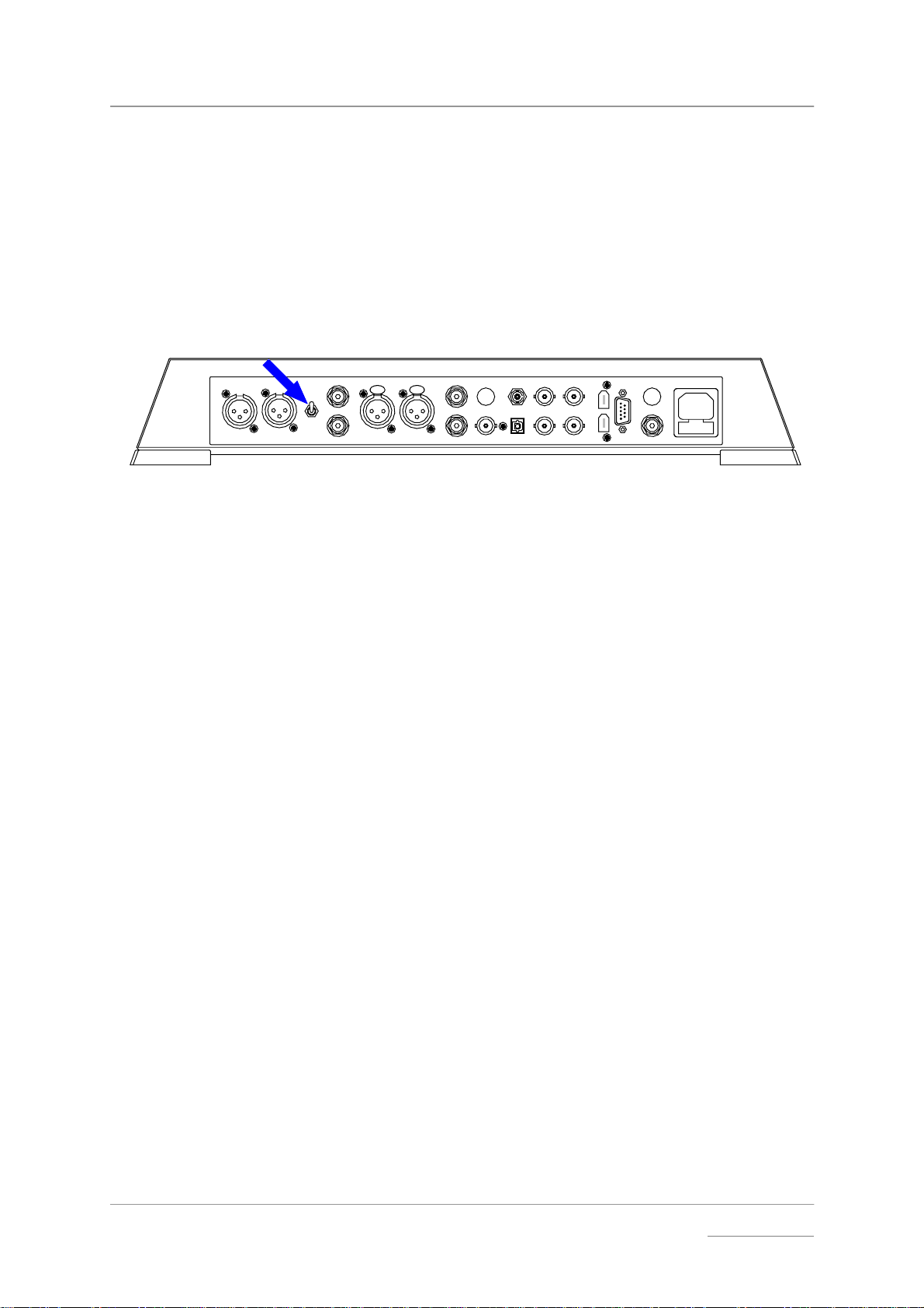
Step 4 - Using Elgar Plus in Master Mode
If your CD transport (or other source equipment sampling at 44.1kS/s) has a
Wordclock input, you can reduce the jitter in your system by using Elgar Plus in
Master mode and slaving the source to it. If not, you can miss out this step.
IMPORTANT! You can only use Master Mode if your source sample rate is 44.1kS/s.
do this: Connect Elgar Plus Wordclock Out connector to the wordclock input on the
source equipment. You may need to set the source equipment to slave to
wordclock.
do this: Hold down the Display button and press the Vol/Bal button to open the menu,
then repeatedly press the Display button until the display shows MS:Slav.
Press the Vol/Bal button repeatedly until the display changes to MS:Mastr.
do this: Allow the menu to time-out.
IMPORTANT! If you are using an Upsampler, this MUST be set to convert a 44.1kS/s source
to either 44.1kS/s, 88.2kS/s, 176.4kS/s or DSD. If not, Elgar Plus will be
unable to lock.
The equipment will take several seconds to re-lock and settle down, then Elgar
Plus will unmute.
A Master mode setup using a CD player is shown below.
DIGITAL OUT
L R OUTPUT
WORDCLOCK
16 bit / 44.1kS/s
LRAES 1 AES 2 RCA1 ST
LEVEL
HIGH
LOW
LR
Balanced
Outputs
To Power Amplifier or Preamplifier
- or -
Unbalanced
Outputs
L
R
44.1kHz Wordclock
PUSH PUSH
LR
Hand Crafted by
The Red Hot CD Player Co.
A
BNC
CH1
TOSLINKRCA2
IN - WORDCLOCK - OU T
DSD / SDIF
Elgar Plus
B
SUC
CH2
1394
POWER
REC OUT
Figure 3 – Using Master Mode with a CD player
Other Settings
The basic set-up procedure is complete. Many more features are available
through the Menu. See the Menu section starting on page 18 for more
information.
Manual filename: Elgar Manual v4.3x.doc Page 13 email: more@dcsltd.co.uk
English version web-site: www.dcsltd.co.uk
dCS Elgar Plus User Manual Manual for Software Issue 4.3x
dCS Ltd September 2004
TYPICAL APPLICATIONS
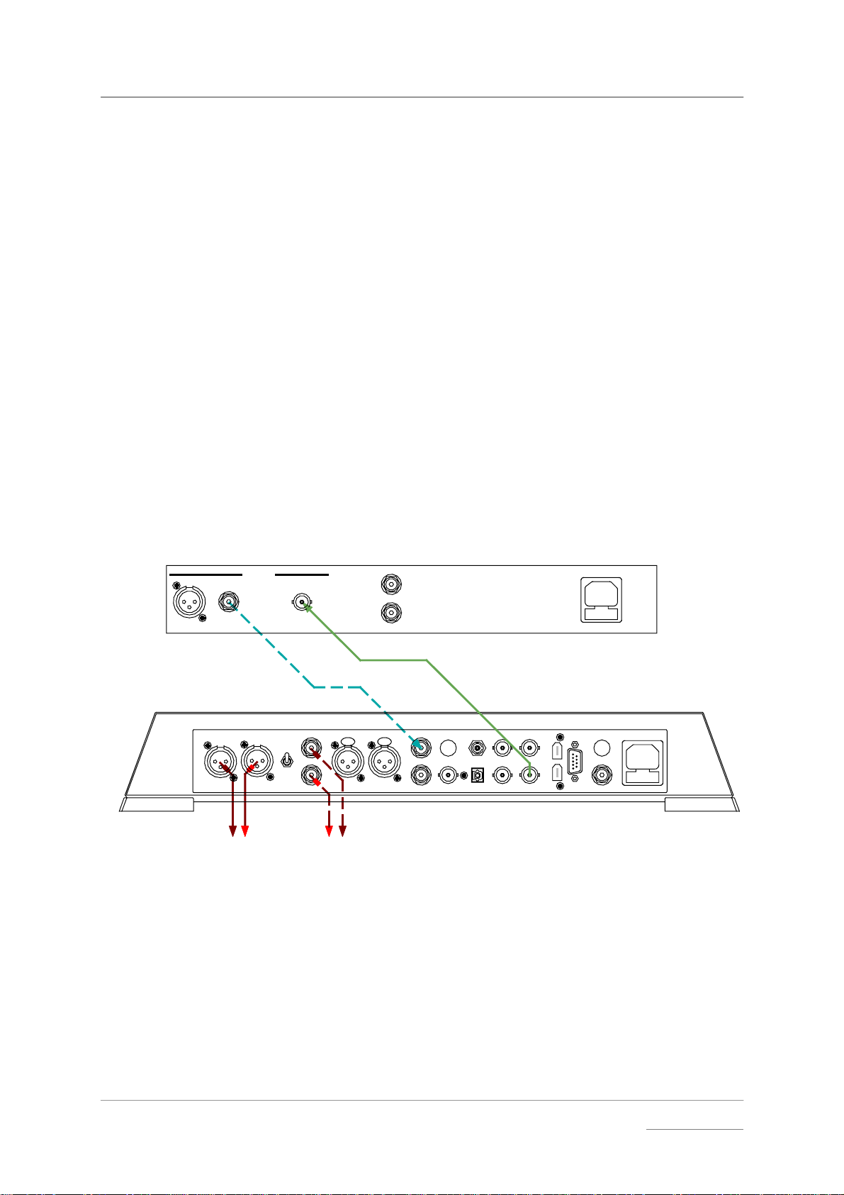
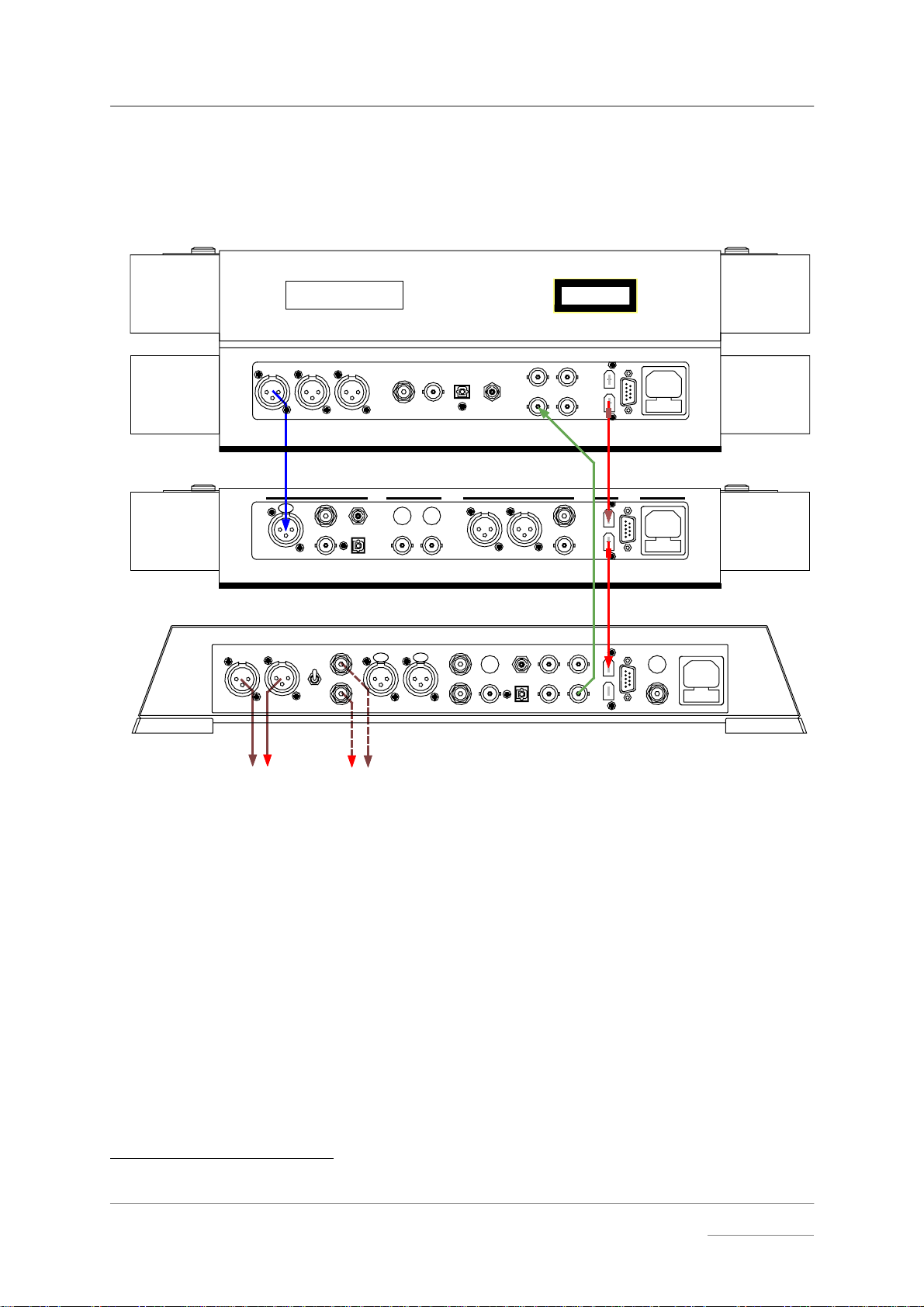
Using an Elgar Plus in Master Mode with Verdi
This setup allows you to play SACDs through the 1394 interface and CDs
through the AES1 interface, with Elgar Plus in Master Mode.
dCS Verdi SACD Transport
CAUTION: VISIBLE AND INVISIBLE
LASER RADIATION. WHEN OPEN,
DO NOT STARE INTO BEAM.
AES 2 AES 3
AES 1
XLR
cable
L R OUTPUT
LR
XLR
LEVEL
HIGH
LOW
R
cables
Balanced
Outputs
- or -
Unbalanced
To Power Amplifier or Preamplifier
Figure 4 - Using Elgar Plus in Master Mode with Verdi
RCA TOSLINK
BNC ST
LRAES 1 AES 2 RCA1 ST
PUSH PUSH
A
BNC
L
RCA phono
cables
Outputs
TOSLINKRCA2
CH1
SDIF
IN - WORDCLOCK - OUT
BNC
cable
CH1
IN - WORDCLOCK - OUT
DSD / SDIF
CLASS 1
LASER PRODUCT
CH2
1394
CH2
1394
SUC
1
1394
cable
SUC
dCS Elgar Plus DAC
B
POWER
REC OUT
do this: Connect up as shown above.
do this: Open Elgar Plus’ menu and run the Factory routine. Use the Input button to
select the AES 1 input. Set the MS page to MS:Mastr and wait for the unit to
settle.
do this: Use the Input button to select the 1394 input wait for the unit to settle. Set the
MS menu page to MS:Mastr and wait for the unit to settle again.
do this: Use the Input button to select the AES1 input for playing CDs or the 1394
interface for playing SACDs.
Verdi v1.2x with Elgar Plus v4.2x will automatically select the right input.
do this: Use the Volume control to set a comfortable listening level. Open the menu
again and choose a different Filter if you wish.
Manual filename: Elgar Manual v4.3x.doc Page 14 email: more@dcsltd.co.uk
English version web-site: www.dcsltd.co.uk
dCS Elgar Plus User Manual Manual for Software Issue 4.3x
dCS Ltd September 2004
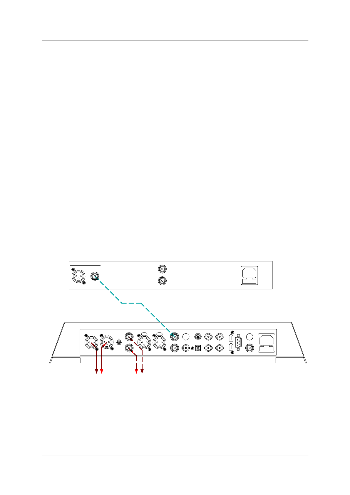
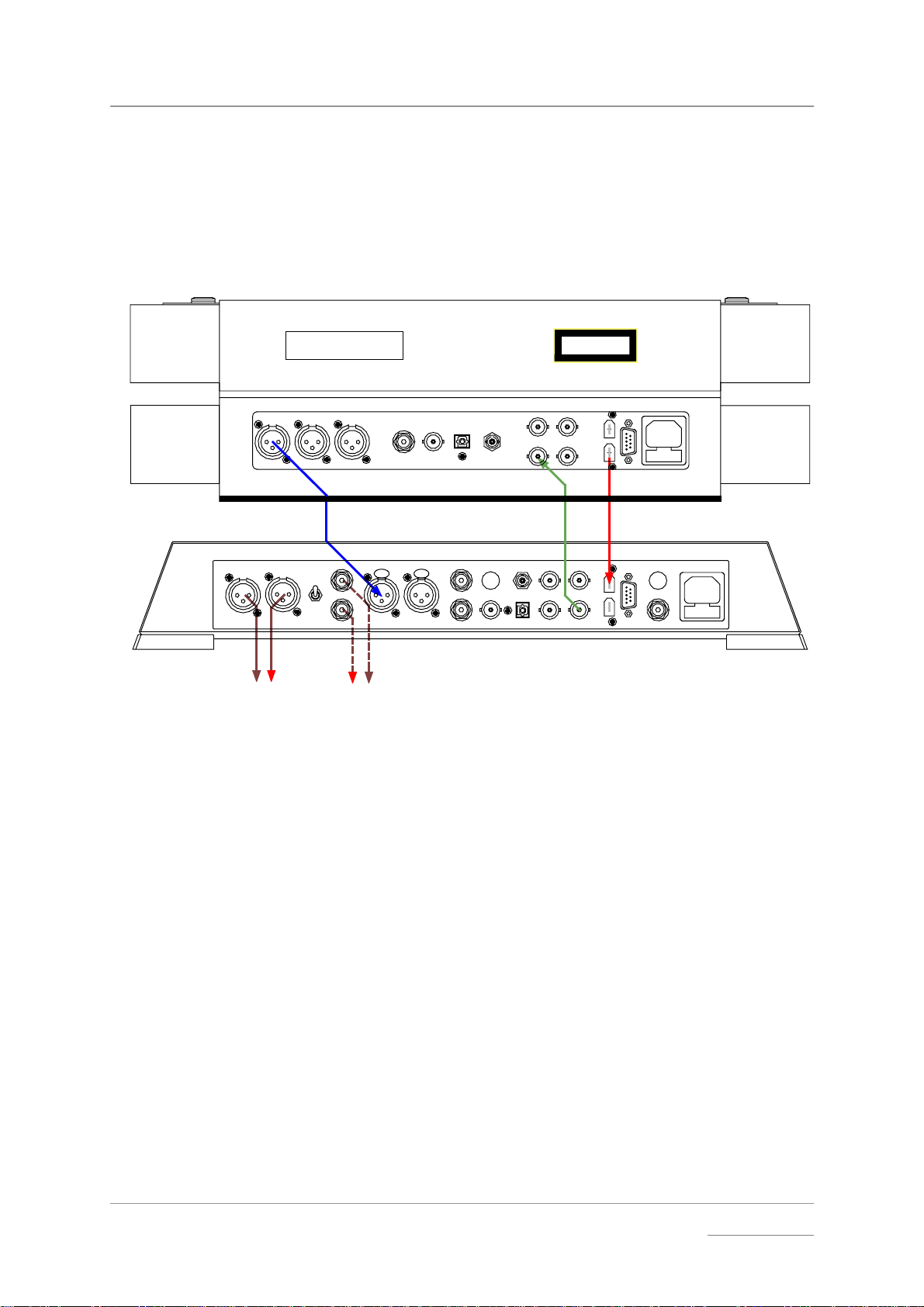
Using Elgar Plus and a 1394-Equipped Purcell with Verdi
This setup allows you to play SACDs and CDs through the 1394 interface,
upsampling
2
the CDs to DSD with a Purcell. Elgar Plus is in Master Mode.
dCS Verdi SACD Transport
CAUTION: VISIBLE AND INVISIBLE
LASER RADIATION. WHEN OPEN,
DO NOT STARE INTO BEAM.
RCA TOSLINK
AES 2 AES 3
AES 1
BNC ST
CH1
IN - WORDCLOCK - OUT
XLR
cable
DIGITAL INP UTS DIGITAL OUTPUT S POWER
AES RCA
PUSH
ST
RCA
TOSLINK
BNC
WORDCLOCK
AB
OUT
IN
AES1 AES2
SDIF
BNC
cable
BNC
CLASS 1
LASER PRODUCT
CH2
1394
OPTION
1394
SUC
1
1394
cable
SUC
1
1394
cable
dCS Purcell Upsampler
dCS Elgar Plus DAC
L R OUTPUT
LR
XLR
cables
Balanced
Outputs
LEVEL
HIGH
- or -
LRAES 1 AES 2 RCA1 ST
PUSH PUSH
LOW
RL
RCA phono
Unbalanced
cables
Outputs
A
BNC
CH1
TOSLINKRCA2
CH2
DSD / SDIF
IN - WORDCLOCK - OUT
B
SUC
1394
REC OUT
POWER
To Power Amplifier or Preamplifier
Figure 5 - Using Elgar Plus in Master Mode with Verdi and Purcell
do this: Connect up as shown above.
do this: Open Elgar Plus’ and Purcell’s menu and run the Factory routines.
do this: Purcell set-up: Use the Input button to select the AES 1 input. Use the Output
button to select 44.1→→→→DSD.
do this: Elgar Plus set-up: Use the Input button to select the 1394 input and wait for the
unit to settle. Set the MS menu page to MS:Mastr and wait for the unit to settle
again. Use the Input button to select either the SACD feed (Verdi) or the
upsampled CD feed (Purcell).
Verdi v1.2x with Elgar Plus v4.2x will automatically select the active input.
do this: Use the Volume control to set a comfortable listening level. Open the menu
again and choose a different Filter if you wish.
2
Yes, we know it should have no effect.
Manual filename: Elgar Manual v4.3x.doc Page 15 email: more@dcsltd.co.uk
English version web-site: www.dcsltd.co.uk
dCS Elgar Plus User Manual Manual for Software Issue 4.3x
dCS Ltd September 2004
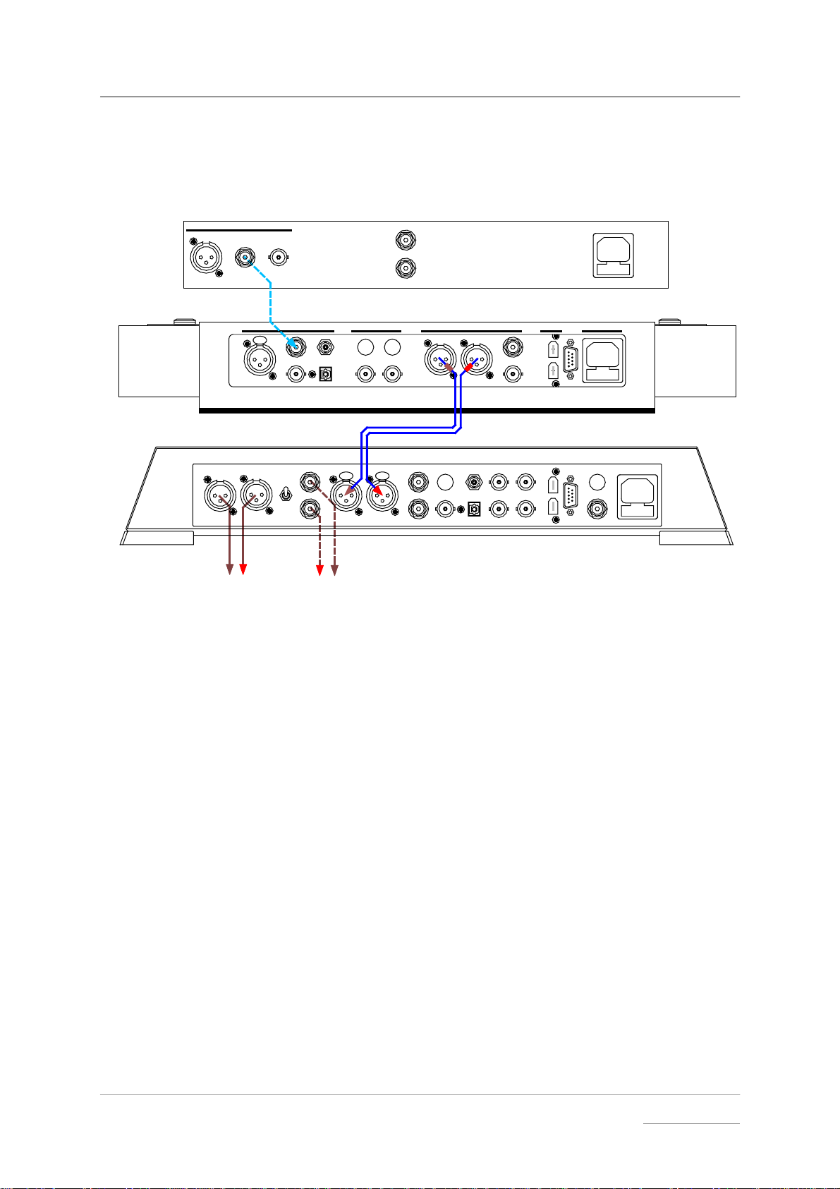
Using Elgar Plus with a Standard Purcell and a CD Player
If your Purcell is not 1394-equipped, you can still upsample the output from a
standard CD player to 24 bit 192kS/s.
DIGITAL OUT
L
R
Hand Crafted by
The Red Hot CD Player Co.
RCA phono
cable
AES RCA
LROUTPUT
LR
XLR
cables
Balanced
Outputs
DIGITAL INP UTS DIGITAL OUTPUT S POWER
PUSH
ST
RCA
TOSLINK
BNC
LRAES 1 AES 2 RCA1 ST
LEVEL
HIGH
LOW
RL
Unbalanced
- or Outputs
WORDCLOCK
AB
OUT
IN
PUSH PUSH
RCA phono
cables
To Power Amplifier or Preamplifier
Figure 6 - Using Elgar Plus with Purcell and a CD player
do this: Connect up as shown above.
AES1 AES2
A
BNC
XLR
cables
TOSLINKRCA2
BNC
cable
BNC
CH1
DSD / SDI F
IN - WORDCLOC K - O UT
OPTION
SUC
1394
1
dCS Elgar Plus DAC
B
SUC
dCS P urc ell U p sam p ler
CH2
1394
REC OUT
POWER
Purcell setup:
do this: Open the menu and run the Factory routine. You can connect any of Purcell’s
digital inputs to the CD player - use Purcell’s Input button to select it. Use the
Output button to set the 44.1→→→→192 conversion.
Elgar Plus setup:
do this: Open the menu, run the Factory and RstSync routines. Use the Input button to
select AES 1 AND AES 2 inputs. Use the Volume control to set a comfortable
listening level. Open the menu again and choose a different Filter if you wish.
Manual filename: Elgar Manual v4.3x.doc Page 16 email: more@dcsltd.co.uk
English version web-site: www.dcsltd.co.uk

dCS Elgar Plus User Manual Manual for Software Issue 4.3x
dCS Ltd September 2004
Manual filename: Elgar Manual v4.3x.doc Page 17 email: more@dcsltd.co.uk
English version web-site: www.dcsltd.co.uk
dCS Elgar Plus User Manual Manual for Software Issue 4.3x
g
-
-
y
dCS Ltd September 2004
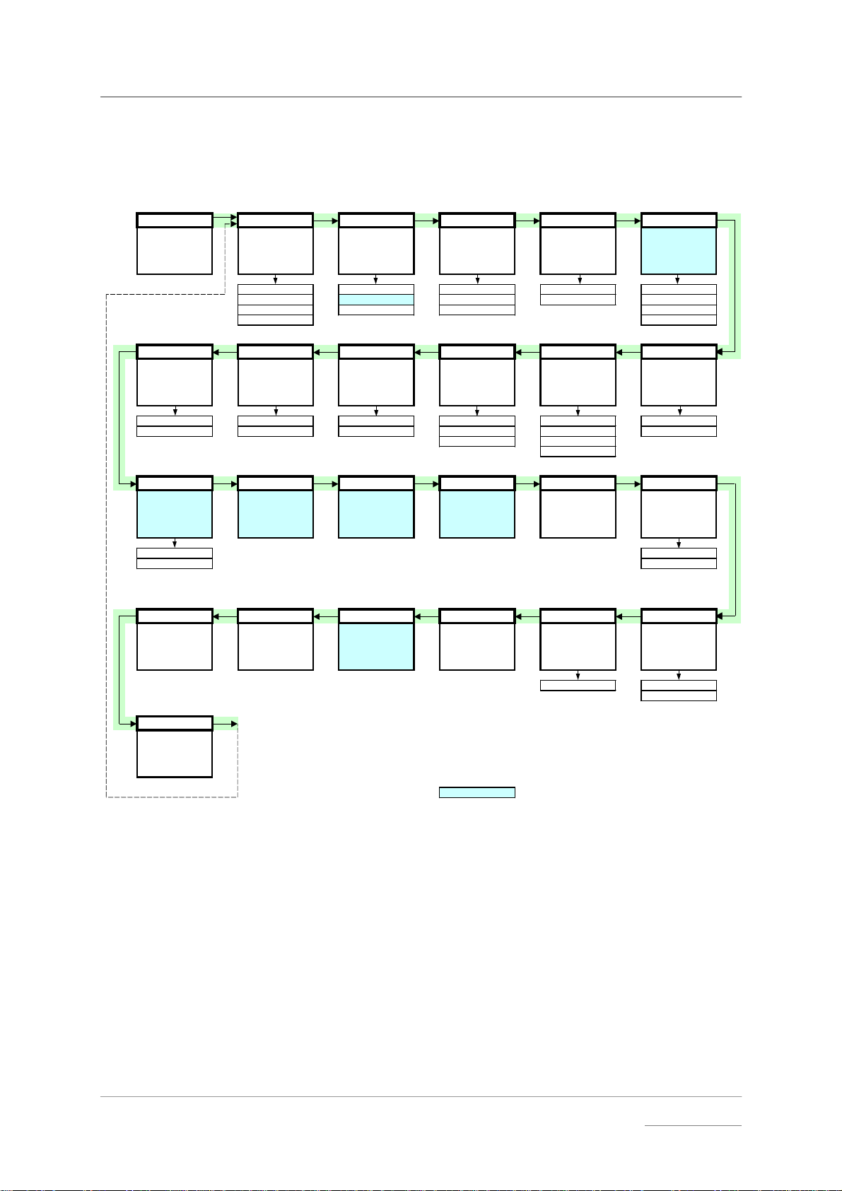
THE SOFTWARE – THE MENU
To open th e Menu, hol d down "Vol / Bal " and press "D isplay" .
To page th rough the M enu, pre ss "Display ".
To select, display or change an option, press "Vol / Bal".
Menu Filter x Master/Slave Mute: Fade Dual AES
First page of t he
Menu
Select s an optio nal
filter if av ailable
Filter 1 MS:Mast Mute:Nor Fade:On Off
Filter 2 MS:Slav Mute:Fst Fade:Off On
.... MS:Sync Mute:Slw Auto
Filter n Lock
Changes the
behaviour of the
selected input
Sets the Mute fade-
out rate
PLL TimeOut Global Bal mode Disp Swap
Sets the PLL
tracking bandwidth
PLL:Fi ne Normal Vol :Gl ob Bal:Bar Disp:Vol Swap:Off
PLL:Wide Long Vol:Inp Bal :Num Disp:Fs Swap:On
Sets the Functio n
Menu time-out
delay
Stores global or
input-related
settings
Sets the balance
display mode
Bal:dBs Disp:Fs+
Audio fades up
during un muting
after relock
Sets the default
display
Disp:Inp
Enables Dual AES
operati on
Reverse the Left
and Right outputs
NAud Ch.Check Ph.Check Burn In Test Issue
Controls muting
when receivin
audio dat a (e.g. CD
Use with care!
non
ROM)
NAud:Mut 4.3x
NAud:Ign Db 2.06
Outputs tone on L
channel onl
then R
channel o nly
Outputs noise on
both channels then
inverts R
Outputs modulated
pink noise to burn-
in your system
CAUTION! LOUD!
Runs a displ ay test
routine
software version
Rst Sync Factory CDUpdate Contact Serial Temp
Resets all inputs to
Slave mode
Restores standar d
factory settings
Starts software
update from a dCS
CD
Displays dCS emai l
address
Displays the unit
full serial number
ELG-?-?-?-?-? Celsius
End
Closes the Function
Menu
= feature is not available in DSD mode
Figure 7 – Function Menu flow chart
Displays the
number
Displays the
internal
temperature
Fahrenheit
Manual filename: Elgar Manual v4.3x.doc Page 18 email: more@dcsltd.co.uk
English version web-site: www.dcsltd.co.uk

dCS Elgar Plus User Manual Manual for Software Issue 4.3x
dCS Ltd September 2004
Using the Function Menu
The Function Menu gives the user access to a wide range of additional
features. It also allows new features and performance enhancements to be
added at a later date by software upgrades.
Opening the Menu
The Function Menu is controlled by two buttons:
• press Vol/Bal and Display buttons at the same time to open the Menu.
• the Vol/Bal button doubles as the
• the Display button pages forward through the Menu - the
If you have a dCS Remote Control, you can use this to access the menu:
Select button.
Step button.
Types of Menu Page
• the Function button opens the Menu and doubles as the
• the ↑↑↑↑ button pages forward through the Menu - the
• the ↓↓↓↓ button pages backward through the Menu - the
Select button.
Step button.
Step Back button.
When you first open the Function Menu, the display will show Menu.
Successive presses of the
Step button page through the Menu. You cannot go
directly to any particular page, but must enter at the top of the Menu and then
page through until you reach the page you want.
There are three types of page in the Menu - Parameter Pages, Information
Pages and Test Pages.
Parameter pages allow the user to check and also change the current settings
of the operating parameters, for example Filter. When a parameter page is
displayed, the first press of the
Subsequent presses of the
Select button change the page setting.
Select button shows the current setting.
Information pages display information about the unit, for example Software
Issue. When an information page is displayed, pressing the
Select button
displays the information held on that page.
Test pages allow the user to initiate a number of useful routines, for example
Channel Chec k. When a Test page is displayed, pressing the
Select button
starts the test routine.
Closing the Menu
There are two ways to close the menu and return to normal operation. The
easiest way is to wait 5 seconds for the unit to time-out and revert to the
standard display. Alternatively, use the
display shows End and then press the
Step button to page forward until the
Select button once.
If the unit times out before the operation in hand has been completed, simply reenter the menu, page forward (or backward) and continue where you left off. If
you find the 5 second time-out difficult to use, you can extend it to 30 seconds
by changing the TimeOut setting to Long.
Manual filename: Elgar Manual v4.3x.doc Page 19 email: more@dcsltd.co.uk
English version web-site: www.dcsltd.co.uk

dCS Elgar Plus User Manual Manual for Software Issue 4.3x
dCS Ltd September 2004
Menu Sequence
Use the flow chart (Figure 7) or the Control Summary sheet to guide you
through the Menu more quickly.
The following explanation deals with the Function Menu pages in the sequence
they occur in the Menu
with the last operation being closing the Menu. After you have become more
familiar with the Menu, you will find it more convenient to perform all the
Function Menu operations in one go before finally closing the Menu.
Filter
Filter – Anti-Imaging Filter Setting
FilterFilter
Elgar Plus offers a choice of 4 interpolation filters for 5 sample rates (32kS/s,
44.1kS/s, 48kS/s, 88.2kS/s and 96kS/s) and 6 for two (192kS/s and 176.4kS/s).
The filters offer differing responses. In each case, Filters 1-4 are symmetrical
filters (with time response before a transition the mirror image of time response
after). Filter 1 offers the sharpest cut-off, least Nyquist imaging but longest
energy smear. F ilter 4 gives the gentlest roll-off (usually with significant Nyquist
imaging) but the shortest transient response with least energy smear. Filter 5 is
a Gaussian filter, and Filter 6 is an asymmetrical filter – there is almost no time
response prior to the initial step.
For units fitted with a 1394 interface, DSD mode also offers four filters, but
these are intended to progressively reduce the out-of-band noise level. Filter 1
generally gives the widest bandwidth, but results are system dependent – if
your system gives undesirable effects with Filter 1, try (in this order) Filter 2
then Filter 3 then Filter 4. These reduce the out-of-band energy at the
expense of reduced bandwidth. Filter 4 is really intended for metering
applications, not for listening.
3
. The use of each page is shown on an individual basis,
Elgar Plus remembers the last filter selection made for every sample rate. So, if
you choose Filter 4 for 96kS/s and Filter 6 for 192kS/s, these separate
settings will be stored and loaded when the incoming sample rate changes
(usually when selecting a different input or changing the Upsampler settings).
Selecting a Filter x
We encourage you to experiment with the filters, to find the one that sounds
best for your particular application. Do not assume that one filter is best for all
applications!
4
do this: Assume for the purpose of this illustration that the sample rate is 96kS/s and
Filter is currently set to Filter 1. Open the Function Menu and step through
until the display shows Filter 1.
3
A minor software update may change the order of the menu items or add an option. If this happens, the
Control Summary sheet may be updated before the manual.
4
The reports we receive from users suggest that Filter 2 is well suited to some classical music, and that Filters
3 and sometimes 4 suit rock. Filters 5 and 6 are too new to have reports on, although the user may wish to
refer to “Effects in High Sample Rate Audio Material”, by M.J.Story, R.Kelly, D.A.McLeod, M.N.Harris,
presented at the 20
dCS web-site.
th
Tonmeister Tagung at Karlsruhe in November 1998. This paper is available from the
Manual filename: Elgar Manual v4.3x.doc Page 20 email: more@dcsltd.co.uk
English version web-site: www.dcsltd.co.uk

dCS Elgar Plus User Manual Manual for Software Issue 4.3x
dCS Ltd September 2004
do this: Press the Select button slowly several times. The display will in turn show:
Filter 2, Filter 3, ... and finally Filter 1 again. Select the filter you want to use
then wait for the Function Menu to time-out.
There is a slight delay whilst the unit changes filters, during which it will not
respond to further button presses. Selecting the most appropriate filter is simply
a matter of flipping through the options as you play a CD and choosing the one
that you think sounds best. Try listening for changes in imaging, ambience and
low level information, bass definition and vocal clarity.
You can change filters more quickly from the listening position using the Filter
button on the Remote Control, see page 43.
MS
MS – Master/Slave Operation
MSMS
This is set on a per input basis, and determines whether that input acts as a
master or a slave. The options available (independently, for each input) are:
MS:Slav (Slave) In slave mode (most DACs operate in this mode)
the PLL locks to the incoming signal, and tracks it. This
setting is not available in DSD mode.
MS:Mastr (Master) In master mode, Elgar Plus acts as a master
clock, and outputs an autonomous 44.1kHz clock on
Wordclock Out. This might go, for example, to a CD
transport. The CD transport output is then locked to the
DAC VCXO, and the DAC only has to decode the data
coming in – it knows the clock frequency.
MS:Sync In sync mode, the PLL locks to a master clock (or other
clock source) connected to Wordclock In while taking
data from the selected input. The source must also be
locked to the master clock, or generating the clock. If the
Wordclock is not at a standard frequency, is out of
capture range or is a “superclock”, the unit will display
Locking…, Fs=??? for 1 minute, then Revert to Slav e
for 10 seconds and reset itself to MS:Slav.
There are some restrictions on master mode operation. The source (usually a
CD transport or player) must run at 44.1kS/s ONLY. Elgar Plus may be used in
this mode with an Upsampler, but the Upsampler output must be set to
44.1kS/s, 88.2kS/s, 176.4kS/s or DSD.
Setting to Master Mode x
If you wish to use master mode (we recommend this for CD transports that will
accept a 44.1kHz word clock), then do the following:
do this: Connect the CD transport (or other source equipment) to Elgar Plus and select
that input.
do this: Connect Wordclock Out to the wordclock input on the CD transport.
do this: Open the Menu and step through until the display shows MS: Slav.
do this: Press the
Select button to change the display to MS: Mastr.
(Run through this sequence again if you want to change back to MS:Slav.)
If a source is connected and selected, Elgar Plus will display d 44.1, then
MS:Mastr and 44.1kS/s alternately for about 10 seconds. After that it will
enable its outputs and is ready for listening.
Manual filename: Elgar Manual v4.3x.doc Page 21 email: more@dcsltd.co.uk
English version web-site: www.dcsltd.co.uk

dCS Elgar Plus User Manual Manual for Software Issue 4.3x
dCS Ltd September 2004
If you are using an Upsampler set for 176.4kS/s Dual AES output, select the
Dual AES input. The displays will then be d 88.2, then MS:Mastr and 176.4kS
alternately for about 10 seconds.
If you are using an Upsampler set for DSD output and your Elgar Plus is fitted
with a 1394 interface, select the 1394 input. The displays will then be Wait…,
then MS:Mastr and 1394 alternately for about 10 seconds.
If you attempt to use a input sample rate that is not a multiple of 44.1kS/s (for
example 192kS/s), the unit will detect this and the following message will scroll
across the display:
“Can’t Use Input Frequency in Master Mode. Press ..... Button to Slave”
If you press the button mentioned in the scrolling message (Function for Delius,
Phase for Elgar), the selected input will be reset to Slav.
If you get stuck, use the Rst Sync menu to reset the unit.
Mute
Mute - Mute Fade Time
MuteMute
This sets the length of the fade-out time before muting and the fade-in time
before unmuting.
do this: Open the Function Menu and step through until you come to the Mute page.
Press the
Select button repeatedly and the display will cycle through:
Mute:Nor Normal muting – audio fades up and down in 0.5
Mute:Fst Fast muting – audio fades up and down instantly.
Mute:Slw Slow muting – audio fades up and down in 2 seconds.
do this: Choose whichever you prefer and wait for time-out.
Fade
Fade – Fade Behaviour After Re-Lock
FadeFade
This feature fades the audio signal up gradually after locking to a source or
changing inputs
do this: Open the Function Menu and step through until you reach the Fade page. The
display shows Fade-Off or Fade-On.
do this: Press the
Select button to toggle between these settings and wait for time out.
With Fade set to On, the unit will take longer to respond to some commands as
nothing will change until the fade up / down is complete.
seconds.
Manual filename: Elgar Manual v4.3x.doc Page 22 email: more@dcsltd.co.uk
English version web-site: www.dcsltd.co.uk

dCS Elgar Plus User Manual Manual for Software Issue 4.3x
dCS Ltd September 2004
Dual AES
Dual AES – Dual AES Mode
Dual AESDual AES
The Dual AES interface was developed by dCS to allow 88.2 or 96kS/s data
streams to be recorded on equipment designed for 44.1 or 48kS/s operation. It
allows a stereo pair of 24/96 data to be recorded on a 4-track digital recorder.
Dual AES mode has become a de-facto standard, appearing on an ever
increasing array of products. Since then, we have developed the Dual AES
interface further to operate at up to 192kS/s, doubling the available audio
bandwidth a second time.
All dCS non-optical single-wire interfaces are capable of 24/96 operation, but
some of our audiophile customers have told us there are extra sonic
improvements to be gained from using Dual AES for 24/96 instead. The reason
for this is certainly not obvious – the digits appear to be the same, it is not
related to jitter.
For 24/192 operation there is no choice but Dual AES. Even our high-speed
single wire interfaces are not currently fast enough.
There are certain requirements for successful Dual AES operation. Obviously,
the source must generate a true Dual AES data stream, not two single AES
outputs. The two cables should be similar in length (less than 3m difference).
The two cables must be connected the right way around or the channels will be
swapped.
Changing inputs between single wire and Dual AES may cause the DAC to
default to single AES mode. To avoid this problem, the Dual AES page offers
the following four options:
Off Disables Dual AES mode for when no Dual AES capable
sources are in use.
On Allows Dual AES mode to be manually selected from the
front panel Input button (see page 37) or the Remote
Control, (see page 43).
Auto Elgar Plus detects single wire or Dual AES mode from
the message flags in the data stream and sets the mode
accordingly. If a Dual AES source is detected but only
one wire is connected, it will lock to the source as single
AES but flash either the AES1 or AES2 indicator to warn
you that one cable is missing.
Lock If both AES 1 and AES 2 are active, selecting either AES
input in this mode forces the unit into Dual AES mode. If
only one wire is connected, the unit warns you of this by
flashing the indicator for the missing wire. Lock mode is
particularly useful when using an Upsampler –
upsampling everything to 176.4 or 192kS/s Dual AES. In
this case, leave Elgar Plus set to Lock mode and select
inputs on the Upsampler.
IMPORTANT! Note that not all Dual AES capable equipment sets the message flags
correctly. If this is the case, do not use Auto mode. You can use it with
confidence on dCS equipment.
do this: To select the Dual AES mode you require, open the Function Menu and step
through until the display shows Dual AES.
do this: Press the
options. When you reach the one you want, wait for the menu to time out.
Manual filename: Elgar Manual v4.3x.doc Page 23 email: more@dcsltd.co.uk
English version web-site: www.dcsltd.co.uk
Select button repeatedly and the display will cycle through the

dCS Elgar Plus User Manual Manual for Software Issue 4.3x
dCS Ltd September 2004
Swap
Swap - Swap Channels
SwapSwap
If you have run the Channel Check test and decided the channels are reversed,
you can swap the channels back digitally as follows.
do this: Assuming the unit is set for swap off, open the Function Menu and step through
until the display shows Swap:Off.
do this: Press the
Select button once.
The display will change to Swap:On.
do this: Run through this sequence again if you want to swap back.
The Swap setting is NOT remembered when you switch off. If your channels are
swapped, check the wiring between units and correct the error.
Disp
Disp - Default Display
DispDisp
This feature allows you to choose what Elgar Plus displays when music is
playing
do this: Open the Function Menu and step through until you come to the Disp page.
Press the
Select button repeatedly and the display will cycle through the
following :
Disp:Vol The display reverts to Volume after time-out (e.g.
Disp:Fs The display reverts to Sample Rate after time-out (e.g.
Disp:Fs+ The display reverts to Input Bits + Sample Rate (format)
Disp:Inp The display reverts to the selected input after time-out
do this: Choose whichever you prefer and wait for time-out.
Bal Mode
Bal Mode - Balance Information Display
Bal ModeBal Mode
Use this to select one of two types of balance display.
do this: Open the Function Menu and step through until the display shows Bal:Bar or
Bal:Num.
do this: Press
Select to change between the two.
Bal:Bar displays the channel balance as two bars, this may be easier to read
from a distance:
▌▌▌▌▐▐▐▐ Balance Central
▌▌▌▌ Balance to left
▐▐▐▐ Balance to right
Vol -12.0).
44.1kS/s).
after time-out (e.g. 24/192). If receiving digital silence, 0
input bits will be correctly displayed.
(e.g. AES1).
Bal:Num displays channel balance as two percentages:
100% 100% Balance central
100% 0% Balance to left
0% 100% Balance to right
Manual filename: Elgar Manual v4.3x.doc Page 24 email: more@dcsltd.co.uk
English version web-site: www.dcsltd.co.uk

dCS Elgar Plus User Manual Manual for Software Issue 4.3x
dCS Ltd September 2004
Global
Global – Global/Local Volume
GlobalGlobal
Elgar Plus can store Volume settings in two ways:
• Applying the same Volume setting to all inputs (Global volume).
• Using different settings for each input (Local volume, or Input specific). This
is useful where the average loudness (and so the preferred Volume setting)
changes from source to source.
To change this setting:
do this: Open the Function Menu and step through until you reach the Vol page. The
display shows Vol:Glob or Vol:Inp.
do this: Press the
TimeOut
TimeOut – Menu Time Out Setting
TimeOutTi meOut
Select button to choose one of these settings and wait for time out.
If you find the 5 second time out period for the menu is too short, use this option
to change the time out period to 30 seconds.
do this: Open the Menu and step through until the display shows Timeout.
do this: Press the
do this: Press the
Select button once and the display will show Normal.
Select button again and the display will change to Long.
do this: Repeat this if you want to change back.
PLL
PLL - PLL Tracking bandwidth
PLLPLL
In slave mode, the PLL (Phase Locked Loop) synchronises Elgar Plus’ internal
crystal clocks to the incoming data stream. The system runs through two
different modes while locking. The final mode (fine lock) has a very narrow
bandwidth which rejects jitter generated by the source. This is the normal PLL
setting and gives best results with a stable source. It takes about 6 seconds to
lock.
Some CD players (even some very expensive ones!) generate a high level of
jitter and this can cause Elgar Plus to intermittently lose fine lock and mute the
Analogue Outputs. This menu option forces the PLL to stay in a wide-band
mode, allowing it to track larger variations in the source sample rate. In this
mode, the unit locks in less than 100 milliseconds.
To change the setting:
do this: Open the Function Menu and step through until the display shows PLL: Fine or
PLL: Wide.
do this: Press the
if you are having locking problems.
If you are using Elgar Plus in master mode or with a Master Clock, the PLL
should be set to PLL:Fine, otherwise the jitter improvement will be lost.
Select button to change between these two settings. Select PLL:Wide
Manual filename: Elgar Manual v4.3x.doc Page 25 email: more@dcsltd.co.uk
English version web-site: www.dcsltd.co.uk

dCS Elgar Plus User Manual Manual for Software Issue 4.3x
dCS Ltd September 2004
NAud
NAud - Non Audio Muting
NAud NAud
Elgar Plus is normally set to mute if the Non-Audio message flag in the incoming
data stream is On – identifying the source as a corrupt data stream, CD-ROM or
other non-audio format.
We have found that some audio CDs actually have the Non-Audio flag set! To
listen to such disks, the automatic muting must be TEMPORARILY disabled.
IMPORTANT! Listening to a CD-ROM is very unpleasant and can cause damage to your
ears, power amplifier and loudspeakers. Use this mode with care. You
should turn Non-Audio Muting back on as soon as possible – we advise you
not to leave Elgar Plus in this mode.
Override Non-Audio Muting x
The most convenient way to over-ride the Non-Audio muting for individual
tracks is as follows.
do this: When NonAudio is displayed, press the Mute button. Elgar Plus will play the
track normally. Press the Mute button again to mute the outputs and restore
Non-Audio muting.
The over-ride is cancelled at power down or when the unit re-locks, avoiding the
risk that the unit will be left for extended periods without protection.
Disabling Non-Audio Muting x
If for some reason, you need to disable Non-Audio muting for longer periods,
you can turn it off in the Function Menu as follows.
do this: Open the Function Menu and step through until the display shows NAud:Mut.
do this: To ignore the non-audio flag, press the
Select button once and the display will
change to NAud:Ign.
Elgar Plus is now set to ignore non-audio message flags – and your protection
against playing non-audio data is removed. When powered up in this mode,
“Ignoring Non-Audio Flag” scrolls across the display to warn you.
Restoring Non-Audio Muting x
To turn non-audio muting back on:
do this: Open the Function Menu and step through until the display shows NAud:Ign.
do this: Press the
Select button once and the display will change to NAud:Mut.
Manual filename: Elgar Manual v4.3x.doc Page 26 email: more@dcsltd.co.uk
English version web-site: www.dcsltd.co.uk

dCS Elgar Plus User Manual Manual for Software Issue 4.3x
dCS Ltd September 2004
Ch.Check
Ch.Check - Channel Check Test
Ch.CheckCh.Check
Use this feature to check if the stereo outputs on your system are swapped. It is
disabled when in DSD/SACD mode.
do this: Set up your system to play music at a comfortable level.
do this: Open the Menu and step through until the display shows:
Ch.Check
do this: Press the Select button once to start the test. After briefly displaying Wait, the
following sequence occurs:
Left
A modulated tone should appear on the left channel only for several seconds.
None
Both outputs are muted for a second.
Right
A modulated tone should appear on the right channel only for several seconds.
This is displayed briefly at the end of the test.
If the channels are swapped, check for wiring errors from the unit output
onwards. If you correct this temporarily using the Swap function on a dCS DAC,
note that the Swap setting is NOT remembered at power down.
Ph.Check
Ph.Check - Phase Check Test
Ph.CheckPh.Check
Use this feature to check if one channel in your system is phase inverted
disabled when in DSD/SACD mode.
do this: Set up your system to play music at a comfortable level.
do this: Open the Menu and step through until the display shows:
do this: Press the Select button once to start the test.
After briefly displaying Wait, the following sequence occurs:
Done
Ph.Check
Normal
5
. It is
In-phase noise appears on both channels for several seconds.
None
Both outputs are muted for a second.
Inverted
5
The ear responds to positive pressure substantially more than it does to negative pressure for low
frequencies, so it is worth getting the phasing correct.
Manual filename: Elgar Manual v4.3x.doc Page 27 email: more@dcsltd.co.uk
English version web-site: www.dcsltd.co.uk

dCS Elgar Plus User Manual Manual for Software Issue 4.3x
dCS Ltd September 2004
A second burst of noise appears on both channels with the right channel
inverted for several seconds.
Done
This is displayed briefly at the end of the test.
If both channels are in-phase the first burst of noise will produce a stable central
image but the second burst will not. If one channel is out of phase, the second
burst will produce a stable stereo image but the first will not.
If there is a phasing error, check for wiring errors from the unit output onwards.
You cannot correct this error on a dCS DAC using the Phase feature as this
inverts both channels.
Burn In
Burn In - Burn-In Signal Generation
Burn InBurn In
IMPORTANT! Read all the steps in this section before starting the System Burn-in routine.
The Burn-in routine outputs a signal at maximum volume.
IMPORTANT! This routine is NOT suitable for burning-in loudspeakers. Ensure your
loudspeakers are disconnected, or your power amplifier is switched off
before starting this routine.
do this: Set up your system volume control to the usual setting.
do this: Open the Menu and step through until the display shows:
do this: Press the Select button once to start the burn-in routine.
do this: To stop the Burn-in signal, press either a
Test
Test - Display Test
TestTest
Use this feature to burn-in your system components with modulated pink noise.
It is disabled when in DSD/SACD mode.
Burn In
Elgar Plus will show the warning messages Caution and Loud in the main
display for 20 seconds and then the burn-in signal will ramp-up from zero to
maximum level over a period of about 10 seconds.
The display cycles through Burn in, Caution and Loud while the Burn In
routine is running.
Step or Select button once. The
display will briefly show:
Done
This runs a test routine to ensure the display is working correctly.
do this: Open the Menu and step through until the display shows Test.
do this: Press the
• The main display lights up then fades from bottom to top.
• The indicator LEDs light up briefly in sequence.
• All indicators light up, along with small squares on the main display. This
• The display shows Done.
Manual filename: Elgar Manual v4.3x.doc Page 28 email: more@dcsltd.co.uk
English version web-site: www.dcsltd.co.uk
Select button once to start the test.
flashes off and on once.

dCS Elgar Plus User Manual Manual for Software Issue 4.3x
dCS Ltd September 2004
Issue
Issue – Software Issue State
IssueIssue
This displays the issue number of the software fitted to your unit. You will need
to check this if you are considering a software upgrade or if your unit
malfunctions.
do this: Open the Menu and step through until the display shows Issue.
do this: Press the
do this: For units fitted with a 1394 interface, press the
Select button once to display the software issue.
Select button again to display
the 1394 interface software issue.
Temp
Temp – Unit Internal Temperature
TempTemp
This displays the temperature inside the unit, close to the crystal oscillators.
do this: Open the Menu and page through until the display shows Temp.
do this: Press the
Press
Serial
Serial – Unit Serial Number
SerialSerial
Select button once to display the temperature in degrees Fahrenheit.
Select again to change to degrees Celsius.
This displays the full serial number, including the hardware configuration code.
We will need this information to assemble upgraded software to suit your unit.
do this: Have a pen and paper handy to note down the number. Open the Menu and
step through until the display shows Serial.
do this: Press the
Select button once and the serial number will scroll across the
display.
Contact
Contact - Contact information
ContactContact
This displays dCS’ email address and web-site URL.
do this: Open the Menu and step through until the display shows Contact.
do this: Press the
Select button once and the contact information will scroll across the
display.
CDUpdate
CDUpdate – Software Update By CD
CDUpdateCDUpdate
Current software for dCS Elgar Plus, Elgar, Delius or Purcell and all Verdi, La
Scala or Verona software features a CD U pdate menu page. You can update
the software inside any of these products loaded with CD Update software
quickly and easily from a CD supplied by dCS.
IMPORTANT! Please follow the latest update instructions supplied with the CD. The
following is for guidance only.
You will need a standard CD Transport, a CD player or a dCS Verdi to play the
CD. A few CD players are not suitable because they upsample to 48kS/s or
change some of the data bits in other ways (one example is the ML37). Don’t
worry - the CD Update routine detects these and stops, preventing any changes
to the internal software.
If you are updating a dCS Upsampler or DAC:
do this: Connect an AES or RCA digital output from the Transport to the Upsampler or
DAC and select the input you have just connected. Disconnect any 1394
interface cables.
Manual filename: Elgar Manual v4.3x.doc Page 29 email: more@dcsltd.co.uk
English version web-site: www.dcsltd.co.uk

dCS Elgar Plus User Manual Manual for Software Issue 4.3x
dCS Ltd September 2004
If you are updating a dCS DAC connected to the Transport through another
device:
do this: Connect an AES or RCA digital output from the other device to the DAC and
select the input you have just connected. Set the other device to bit-for-bit mode
(Cloning on a dCS Upsampler). Disconnect any 1394 interface cables.
If in doubt, connect the DAC directly to the transport.
If you are updating a dCS Verona:
do this: Disconnect ALL cables from the unit, except the power cable. Open the Menu
on the unit to be updated and step through until the display shows CDUpdate.
do this: Make sure the transport is in STOP mode.
do this: Press the
Select button to start the routine.
do this: When the unit displays Cable, connect a BNC cable from the Ext Ref Input to a
BNC SPDIF digital output on the transport. The unit will lock to the transport,
then display Wait.
If you are updating a dCS Transport, the Transport plays the CD and updates
itself, missing out some of the early steps. Disconnect any 1394 interface
cables.
For all dCS units:
do this: RELAX! The update procedure is easy.
do this: Mute your power amplifier.
do this: Insert a dCS CD (containing software for the unit you want to update) into the
transport, making sure it is in STOP mode.
do this: Open the Menu on the unit to be updated and step through until the display
shows CDUpdate.
do this: Press the
Select button to start the routine.
The unit will display Wait while it prepares the flash memory for the update.
After 3-4 minutes, the unit will scroll P lea se St art CD .
do this: Press PLAY.
IMPORTANT! Do not press PLAY before the unit to be updated is ready. This can cause
the download to fail. Use only dCS CDs.
The unit will now inspect the CD, and will display Scanning, while it reads
administrative data.
If there is anything wrong with the dCS CD that has been loaded or it does not
match the product, the unit will display Wrong! or Wrong CD or No Index and
revert to normal operation. Don’t worry – the internal software is unchanged.
Check the CD for dust or scratches.
If it is not a dCS CD at all, the unit will keep repeating Please Start CD, for
about 30 seconds or display Wrong CD and then revert to normal operation.
If the data is correct, the unit will display Track n, where n is a number.
do this: You can move the Transport on to track n, or wait for it to get there of its own
accord.
If the unit has to wait for the right track, it will display Found Track 1, then
Found Track 2, etc, until it finds the right one. Vx.xx will appear on the display
(this is the new software issue number). If the unit displays No Track, repeat
the procedure but manually advance the transport to track n.
Next, the update progress is displayed in one of the following formats:
Manual filename: Elgar Manual v4.3x.doc Page 30 email: more@dcsltd.co.uk
English version web-site: www.dcsltd.co.uk

dCS Elgar Plus User Manual Manual for Software Issue 4.3x
dCS Ltd September 2004
• The display counts up from 0% 0/7 to 99% 0/7, displays Copying, counts
up from 0% 1/7 to 99% 1/7, displays Copying and so on until the last
section is loaded and copied. Some models may use less than 8 sections.
• A moving dot counts down slowly from about 3 to 0.
After about 15 minutes, the update is complete and the unit will reboot itself.
do this: If the CD is still playing, you can stop it now.
do this: If the unit being updated has a 1394 interface, wait until the unit has settled
(about 30 seconds), switch it off for 10 seconds, then on again.
If the unit detects no change in the 1394 interface code, it will boot up as usual
and be ready for use.
If the 1394 interface code has been updated, the unit will load the new code into
the flash memory on the 1394 interface board – this takes about 10 minutes.
While this is taking place, the unit will display a progress bar. Next the unit will
display in sequence: Done 5, Done 4, …, Done 1 then reboot itself again.
The unit is ready for use.
OOPS! If the CD transport stops or becomes disconnected during an update, don’t
worry! The original software is backed up inside the unit. Proceed as
follows:
The checking routine will find a sequencing error and Non Seq or Bad CD! will
appear on the display.
do this: Turn the power off and on to reboot. This message will scroll across the display:
Bad CheckSum – Press Function button to attempt recovery
or Bad CheckSum – Press Mute button to attempt recovery
or Bad CheckSum – Press Menu button to attempt recovery,
depending on the model.
do this: Press the appropriate button once.
The original software is retrieved from the internal backup while displaying
Wait... . This may take a few minutes. When recovery is complete, the unit
re-boots.
do this: Run the CD Update routine again to load the new software.
Manual filename: Elgar Manual v4.3x.doc Page 31 email: more@dcsltd.co.uk
English version web-site: www.dcsltd.co.uk

dCS Elgar Plus User Manual Manual for Software Issue 4.3x
dCS Ltd September 2004
Factory
Factory – Restoring Factory Defaults
FactoryFactory
This feature sets most of the parameters back to the factory default settings.
This can be useful if the settings are accidentally changed and you need to
reset the unit to a standard configuration, or your children play with it.
do this: Open the Menu and step back until the display shows Factory.
do this: Press
Select and leave the menu to time out.
After a few seconds, the unit will re-boot and return to normal operation set up
as follows:
• Input to AES1. The Input selection is automatic if the unit is connected by
a 1394 cable to another dCS unit with current software.
• Filters to Filter1
• Phase to Normal
• Swap to Off
• Master/Slave to MS:Slav on all inputs
• Brightness to Bright 4
• Display to Fs+
• Mute to Off, Normal speed
• Dual AES to Auto if an Upsampler is detected, otherwise Off
• Fade to On
• De-Emphasis to Auto
• Balance to centre
• Balance display to Bal:Num
• Volume to –30, Global
• Timeout to Normal
• PLL mode to Fine
• Non-Audio to Mute
• Delius only: Output level to Out :2V
• Other settings as you last used them.
Rst Sync
Rst Sync – Setting all Inputs to Slave Mode
Rst SyncRst Sync
This feature resets the 1394 input to Sync mode and all other inputs to slave
mode. This can be useful if you have problems setting master mode, or your
children play with it.
do this: Open the Menu and step through until the display shows Rst Sync.
do this: Press
Select and leave the menu to time out.
The display will show Reset. After a few seconds, the unit will re-boot and
return to normal operation set up as follows:
• Master/Slave to MS:Sync on 1394 input
• Master/Slave to MS:Slav on all inputs except 1394
• Other settings as you last used them.
Manual filename: Elgar Manual v4.3x.doc Page 32 email: more@dcsltd.co.uk
English version web-site: www.dcsltd.co.uk

dCS Elgar Plus User Manual Manual for Software Issue 4.3x
dCS Ltd September 2004
Manual filename: Elgar Manual v4.3x.doc Page 33 email: more@dcsltd.co.uk
English version web-site: www.dcsltd.co.uk

dCS Elgar Plus User Manual Manual for Software Issue 4.3x
dCS Ltd September 2004
THE HARDWARE – CONTROLS AND CONNECTORS
Front Panel
ABCD E F G H I JK L
Standby Di splay Phase De-Emphasis Input Mute Volume/Balance
Key to Front Panel
PWR
OPT
SDIF
DSD BNC 1394
dCS Elgar
Reference Digital to Analogue Audio Processor
plus
AES1 AE S2
RCA1 RCA2
TOS ST
Figure 8 – dCS Elgar Plus Front Panel
A Standby / Power button with Standby indicator
B Display or menu
Step button with Display Off
indicator
C Phase button with Phase indicator
D De-Emphasis button
E Status indicator
F Remote control sensor
G Main Display
H Input indicator
I Input selector button
J Mute button with Mute indicator
K Volume / Balance mode or menu
Select button
with Balance mode indicator
L Rotary control
(Upgrader’s note: Elgar plus units manufactured before February 2001 have a
Power switch on the rear panel, the Standby button will not switch the unit on
and off. Also, the functions of the Status and Input indicators were different.)
Standby Button x
This button doubles as a power on / off switch and a standby mode switch.
To switch on, press the Standby button. If power is available, the PWR
indicator will light and Elgar Plus will run through the power up routine. (Note
that the Standby button will not click when turning power on – this is normal.)
When you have finished listening, press the Standby button briefly to set the
unit to standby mode. The Analogue Outputs will mute, all displays will turn off
except the green LED above the Standby button and the PWR indicator on the
Status Indicator. In this mode, Elgar Plus uses less power but stays warm.
To restore normal operation, press the Standby button briefly again. The
Standby LED will turn off and Elgar Plus will power up ready for use.
To switch off completely, press the Standby button and hold it for a few
seconds until the Main Display shows PowerDn, then release it.
Manual filename: Elgar Manual v4.3x.doc Page 34 email: more@dcsltd.co.uk
English version web-site: www.dcsltd.co.uk

dCS Elgar Plus User Manual Manual for Software Issue 4.3x
dCS Ltd September 2004
Display button (Menu Step)
The Display button controls the brightness of the Main display (G) and the
green LEDs above the buttons. When it is pressed for the first time, the display
indicates the present brightness setting in the form Bright x, where x is a
number from 7 (maximum brightness) through to 0 (display off). Successive
button presses will cause the main display to cycle through the following
sequence, getting dimmer with each press:
Bright 7, Bright 6, ....., Bright 1, Bright 0, Bright 7, etc.
The green LEDs are dimmed for settings below Bright 4.
After a few seconds, a setting of Bright 0 blanks the Main display unless the
unit is not locked to a digital source. The green LED above the Display button
indicates that the M ain display has been turned off. Operating any control or
locking to a source while in this mode causes the Main display to turn on
momentarily so you can see what Elgar Plus is doing.
The Display button doubles as the Function Menu
Step button – see page 19
for details.
Phase button x
do this: If you need to correct a phase error on both channels, press the Phase button
to reverse the phase of the Analogue Outputs.
The LED above the Phase button will light to indicate this and the Main displa y
will briefly show Inverted.
do this: Press the Phase button again to restore correct phase. The Main display will
briefly show Normal.
De-Emphasis button x
Recording with 50/15µs high frequency emphasis is a hangover from the days
of recording onto noisy magnetic tapes. To combat tape hiss, the high
frequency part of the music was recorded at a higher level (pre-emphasis). The
high frequency response was corrected at playback by a de-emphasis filter,
reducing the hiss level as well.
Some early CDs were recorded with emphasis, but more recent disks have a
flat frequency response. The emphasis used is recorded in message flags,
encoded into the data stream. On some disks, these flags are incorrect,
resulting in a bumpy frequency response. Elgar Plus can apply de-emphasis for
PCM sources with sample rates of 32, 44.1 or 48kS/s - it is not used at higher
sample rates.
CCITT emphasis is used in digital radio transmissions.
do this: Press the De-Emphasis button repeatedly and the Main display will cycle
through the options:
Manual filename: Elgar Manual v4.3x.doc Page 35 email: more@dcsltd.co.uk
English version web-site: www.dcsltd.co.uk

dCS Elgar Plus User Manual Manual for Software Issue 4.3x
dCS Ltd September 2004
None Applies no de-emphasis and ignores message
flags.
Auto Automatically applies the de-emphasis curve
indicated by the message flags in the data stream.
When Emphasis is detected, the Main Display
briefly shows the de-emphasis applied.
50/15us Applies 50/15µs de-emphasis curve and ignores
message flags.
CCITT Applies CCITT J17 de-emphasis curve and ignores
message flags.
The De-Emphasis setting is displayed for 5 seconds after the last button press,
then the display reverts to its’ default setting.
do this: It is most convenient to leave Elgar Plus in Auto mode. If the emphasis flag is
wrong, this can be corrected manually using the other 3 settings.
Status Indicator x
This consists of 4 indicators:
• PWR is lit when the unit is powered up.
• OPT is intended for future enhancements.
• SDIF and DSD are input indicators.
Remote Control Sensor x
Point the end of the Remote Control unit towards the sensor for best control
range.
Main Display x
The Main Display tells you what Elgar Plus is doing.
• When not locked to a digital source, the display shows No Input.
• During normal operation, the display will show Volume, Sample Rate (Fs),
Input Wordlength & Sample Rate or Input, depending on the setting of the
Disp option in the Menu (see page 24).
• While locking to a source, the display shows in sequence Locking, followed
by d xxx (detecting the base sample rate) and finally the normal display.
• When adjusting the Volume setting, the display changes to Vol -xx.x. It
changes back to the normal display 5 seconds after the last change.
• When adjusting the Balance setting, the display changes to either two
percentages, two levels in dB or a double bar. The Balance display mode is
set by the Bal item in the Menu (see page 24). The display changes back to
normal 5 seconds after the last change.
Manual filename: Elgar Manual v4.3x.doc Page 36 email: more@dcsltd.co.uk
English version web-site: www.dcsltd.co.uk

dCS Elgar Plus User Manual Manual for Software Issue 4.3x
dCS Ltd September 2004
Input Button and Input Indicator x
The Input button controls which digital input is selected, as shown by the Input
Indicator.
do this: Press the button repeatedly until the required input is shown on the Input
Indicator.
The choices are AES 1 (XLR), AES 2 (XLR), Dual AES (AES1 + AE S 2 on 2 x
XLR), RCA1, RCA2, TOSLINK optical, ST optical, BNC, 1394, DSD (3 x BNC)
or SDIF (3 x BNC). The indicators for the last two are on the Status Indicator.
Dual AES is available only if both AES 1 and AES 2 inputs are connected to a
Dual AES source (see page 23).
The 1394 input is only available if the IEEE 1394 interface is active and a
suitable wordclock is connected to Wordclock In.
Mute Button x
do this: If the unit is locked to a digital source, press the Mute button to mute or unmute
the Analogue Outputs. The Mute indicator will light when the outputs are muted.
If the unit is not locked to a digital source, the Analogue Outputs are
automatically muted, the Mute indicator is lit and the Mute button has no effect.
do this: See NAud on page 26 if you need to over-ride an incorrectly set Non-Audio flag
on a disk or tape.
Volume / Balance button (Menu
Select)
The Rotary Control (L) normally adjusts the Volume.
do this: Press the Volume / Balance button once to change the function of the Rotary
Control to Balance adjustment. The Balance indicator over the button lights
when Balance adjustment is selected. Press the button again to change back
or just wait 5 seconds for the unit to time-out.
The Volume / B alance button doubles as the Function Menu
Select button –
see page 19 for details.
Rotary Control x
This control is dual function. In normal use, it sets the Volume or Balance, but
while the menu is open, it scrolls through that. The rotary control has no end
stop – it will turn continuously.
The Volume and Balance functions are implemented digitally. For best results,
set the Volume to a fairly high level (say between -20.0 and -10.0) while playing
music at typical listening levels. If using a preamplifier Volume control instead,
set Elgar Plus Volume to 0.0 (maximum).
Manual filename: Elgar Manual v4.3x.doc Page 37 email: more@dcsltd.co.uk
English version web-site: www.dcsltd.co.uk

dCS Elgar Plus User Manual Manual for Software Issue 4.3x
dCS Ltd September 2004
Rear Panel
X
MNOPQRTV
ab c
e
Key to Rear Panel
L R OUTPUT
LEVEL
HIGH
LOW
LRAES 1 AES 2 RCA1 ST
PUSH PUSH
A
BNC
S U
CH1
TOSLINKRCA2
IN - WORDCLOCK - OUT
WY
CH2
DSD / SDIF
Z
B
SUC
1394
REC OUT
d
Figure 9 – dCS Elgar Plus Rear Panel
M Balanced analogue outputs L & R on XLR male
connectors
N Output Level switch
O Unbalanced analogue outputs L & R on RCA
phono connectors
P & Q AES/EBU digital inputs AES 1 & AES 2 on XLR
female connector
R & S SPDIF digital inputs RCA1 & RCA2 on RCA phono
connectors
T Spare location for future enhancements
U SPDIF digital input on BNC connector
V SPDIF optical input on ST connector
W SPDIF optical input on Toslink connector
X DSD/SDIF-2 data inputs, CH1 and CH2 on BNC
connectors
Y Wordclock digital Input on BNC connector
Z Wordclock digital Output on BNC connector
a IEEE 1394 interface on two 6-way connectors
b Software Upgrade Connector, 9-way ‘D’ type
c Spare location for future enhancements
d SPDIF digital output REC on RCA phono
connector
eIEC Power inlet
f Mains fuse holder
POWER
f
(Upgrader’s note: Units manufactured before February 2001 were not fitted with
RCA2, Wordclock Out, the 1394 interface or spare locations A & B.)
Output Level Switch
The Output Level switch sets the level for all Analogue Outputs. It should be
set to suit your system – there are two levels: High (6V rms) and Low (2V rms).
The difference between the two settings is 9.5dB. For best results, Elgar Plus’
Volume control should be set to no lower than -20.0 for normal listening levels
with typical music. We suggest you start with the Low setting and change to the
High setting if this is inadequate. Before adjusting the Output Level switch,
please ensure you are not playing music at a high level – the High setting is
noticeably louder.
Manual filename: Elgar Manual v4.3x.doc Page 38 email: more@dcsltd.co.uk
English version web-site: www.dcsltd.co.uk

dCS Elgar Plus User Manual Manual for Software Issue 4.3x
dCS Ltd September 2004
Balanced Analogue Outputs
If your pre or power amplifier has balanced inputs, connect Elgar Plus’
Balanced Analogue Outputs to them. For best results, connection of these
outputs to unbalanced inputs is not recommended – use the Unbalanced
Analogue Outputs instead. Use good quality, screened, XLR audio cables.
Unbalanced Analogue Outputs
For unbalanced equipment, use the Unbalanced Outputs with good quality,
screened, RCA phono audio cables. The Unbalanced Outputs are very high
quality! It is much better to use these for equipment with a single-ended input,
than to use half of a balanced output. Doing so may cause ground loop hum
pickup.
AES/EBU Digital Inputs
The AES 1 and AES 2 inputs may be used individually for digital signals with
sample rates up to 96kS/s. The data format is AES3.
In Dual AES mode, both inputs must be used together. The Dual AES interface
allows a 192, 176.4, 96 or 88.2 kS/s 24 bit signal to be encoded as two
standard 96, 88.2, 48 or 44.1 kS/s 24 bit AES data streams respectively. Elgar
Plus decodes the dual data stream and converts it to wide band analogue. See
Dual AES on page 23 for more information.
IMPORTANT! Please ensure the two AES inputs are correctly connected to the source for
Dual AES operation or the channels will be swapped. This usually involves
connecting AES 1 (or AES A) on the source to AES 1 on Elgar Plus and
AES 2 (or AES B) on the source to AES 2 on Elgar Plus.
Use with 110 ohm screened, twisted pair cable designed for digital audio or RF.
Do not use unscreened cables as they may pick up interference from other
appliances.
SPDIF Digital Inputs
The RCA1, RCA2 and BNC inputs are used individually for digital signals with
sample rates up to 96kS/s. The data format is IEC60958, otherwise known as
SPDIF. RCA connectors are the type commonly found on consumer equipment.
Use with 75 ohm co-axial cables designed for digital audio or RF use. Some
types of audio cable are not suitable and may cause crackling noises or other
malfunctions.
Toslink and ST Optical Inputs
The Toslink and ST inputs are used for optically transmitted digital signals with
sample rates up to 48kS/s. In practice, the interfaces are tested up to 96kS/s
but dCS cannot guarantee this with non-dCS source equipment. The data format
is IEC60958, otherwise known as SPDIF.
Use the Toslink input with Toslink fibre optic cables designed for digital audio
use. Use the ST input with ST style fibre optic cables. Pull off the plastic cover
before use.
Manual filename: Elgar Manual v4.3x.doc Page 39 email: more@dcsltd.co.uk
English version web-site: www.dcsltd.co.uk

dCS Elgar Plus User Manual Manual for Software Issue 4.3x
dCS Ltd September 2004
REC Digital Output
The REC output buffers and loops through the selected single wire input data
with sample rates up to 96kS/s. The data format is the same as the selected
input (i.e. AES3 or IEC60958), the electrical format is SPDIF. It may be
connected to a digital recorder or another DAC. Use with 75 ohm co-axial
cables designed for digital audio or RF use.
IMPORTANT! This output is intended for use with Single AES, RCA, BNC, Toslink or ST
inputs ONLY. If the selected input is in any other format, the REC output
will carry either the left channel data or full scale noise.
IMPORTANT! If the selected input is SPDIF and the Copy Prohibit flag in the source data is
set, the REC output will be the same and you will not be able to record the
data.
1394 Interface
Units fitted with an IEEE 1394 multi-channel interface feature two 6-way 1394
connectors. The active source is selected by the Input button, see page 37.
DSD / SDIF Interface
In this release, the unit accepts DSD data at 2.822MS/s from either 1394
connector. For correct operation, the source must generate a 44.1kHz
wordclock (or be locked to a master clock running at 44.1kHz) and this must be
connected to Elgar Plus’ Wordclock In connector. We recommend using the
1.8 metre long, 6-way IEEE 1394 cable assembly and the BNC cable assembly
provided. See the “IEEE 1394 Overview” section on page 48 for more
information.
This consists of two data inputs, CH1 & CH2 and the Wordclo ck Input, all on
BNC sockets. When a DSD or SDIF-2 data stream is connected and selected
using the Input button, Elgar Plus locks to the Wordclock Input, analyses the
waveforms on the data inputs and automatically selects DSD or SDIF-2
operation. The DSD or SDIF indicator lights up as appropriate. As DSD mode is
fundamentally different to PCM mode, Elgar Plus will take several seconds to
load the necessary software.
The DSD interface accepts single bit data at 2.822MS/s with a 44.1kS/s
Wordclock.
The SDIF-2 interface accepts sample rates from 32 to 96kS/s and requires a
Wordclock.
Connect up the three BNC sockets with 75Ω co-axial cables designed for digital
audio or RF use.
IMPORTANT! Please ensure the 3 cables are correctly connected to the source, otherwise
the interface may malfunction or the channels may be swapped.
The Wordclock Input may be used with a Master Clock to synchronise other
components in your system, connected to Elgar Plus’ other inputs.
Manual filename: Elgar Manual v4.3x.doc Page 40 email: more@dcsltd.co.uk
English version web-site: www.dcsltd.co.uk

dCS Elgar Plus User Manual Manual for Software Issue 4.3x
dCS Ltd September 2004
Wordclock Digital Output
The Wordclock Output is intended to synchronise other equipment to Elgar
Plus. In Master mode, it outputs a fixed frequency master clock, at 44.1kS/s, for
other equipment to lock to. It is disabled in slave or sync modes. See the MS
menu on page 21.
There is no data on this interface. Use with 75 ohm co-axial cables designed for
digital audio or RF use.
SUC
The Software Upgrade Connector is intended to be used by dCS service agents
to load new software into Elgar Plus.
IMPORTANT! Do not connect any other equipment to the SUC connector as this may
damage both Elgar Plus and the equipment so connected. Do not operate
Elgar Plus with a PC connected. Failure to observe this warning will void
the unit’s warranty, and may cause unpleasant effects in your system.
IEC Power Inlet
Use with a 3 - pin IEC type power cable.
Mains Fuse
Additional Information
Replace only with a 20 x 5mm 0.5A T HRC fuse. Please see page 58 for
replacement details.
The rear panel displays the following information about the unit:
• Supply voltage setting, frequency range and rated power.
• Model: dCS Elgar Plus
• The short form of the unit serial number.
We will need the serial number (preferably the full serial number from the menu)
to give you support over the phone, or to ship you software updates.
Manual filename: Elgar Manual v4.3x.doc Page 41 email: more@dcsltd.co.uk
English version web-site: www.dcsltd.co.uk

dCS Elgar Plus User Manual Manual for Software Issue 4.3x
dCS Ltd September 2004
Remote Control
Standby P ur cell
α
β
γ
δ
ε
Function
AES1 AES2
RCA1 RCA2 Phase
FilterBNC Input
V ol/B al Display
Mute
ζ
θ
η
ι
κ
dCS
Figure 10 – The Remote Control
Standby Button
(α) Puts Elgar Plus in Standby mode – this saves energy but keeps the unit
warm and ready for use. Press again to return to normal operation.
Function Button
(β) Opens the Function Menu (see page 19). Use the ↑
page through the menu and press Function again to change a setting. Note
that the menu may time out if there is no activity for 5 seconds.
Manual filename: Elgar Manual v4.3x.doc Page 42 email: more@dcsltd.co.uk
English version web-site: www.dcsltd.co.uk
↑ and ↓↓↓↓ buttons (κ) to
↑↑

dCS Elgar Plus User Manual Manual for Software Issue 4.3x
dCS Ltd September 2004
Input Selector Buttons
(γ) Select individual inputs with the AES1, AES2, RCA1, RCA2 & BNC
buttons. The Input button steps through all the available inputs in sequence,
giving access to those without an individual button. For Dual AES, connect a
suitable source, select AES2 and press the Input button.
Vol/Bal Button
(δ) Switches between Volume mode and Balance mode. Use the ↑
buttons
Balance mode times out after 5 seconds, reverting to Volume mode.
Mute Button
(ε) Press this to mute or unmute the Analogue Outputs.
Purcell Button and LED
Purcell units fitted with software version 1.20 or later and all Grieg units will
accept commands from the Remote Control. Press the Purcell button
the blue LED will light up for about 5 seconds. During this time, the Standby,
Function, Input selector, Filter, ↑↑↑↑, ↓↓↓↓ and Display buttons will control the
Upsampler instead of Elgar Plus.
Sending a Purcell command will keep the Remote Control in Purcell mode (and
the LED on) for another 5 seconds. Press the Purcell button again while the
blue LED is lit to return to Elgar Plus mode (or just wait 5 seconds).
If the blue LED is on, the Upsampler will respond. If it is off, Elgar Plus will
respond.
Phase Button
(θ) Changes the Phase of the analogue outputs to Inverted. The Phase
indicator on the Front Panel will light. Press again to return to Normal.
↑ and ↓↓↓↓
↑↑
(κ) or the Rotary Control on the front panel to alter the settings.
(ζ) and
Filter Button
(η) Changes the interpolation filter setting, giving a different trade-off between
Nyquist image suppression and energy smear. Each sample rate has a
separate Filter setting stored, so Elgar Plus must be locked to a suitable source
before the Filter setting can be changed. This feature is duplicated in the Menu,
see Filter on page 20.
Display button
(ι) Each press reduces the display brightness on a scale from Bright 7 to
Bright 0.
Up and Down (↑↑↑↑ / ↓↓↓↓) buttons
Use these buttons
the Function Menu, see page 19.
Manual filename: Elgar Manual v4.3x.doc Page 43 email: more@dcsltd.co.uk
English version web-site: www.dcsltd.co.uk
(κ) to change Volume and Balance settings or scroll along

dCS Elgar Plus User Manual Manual for Software Issue 4.3x
dCS Ltd September 2004
ELGAR PLUS TECHNICAL INFORMATION
Converter Type
• 5-bit, approximately 3MS/s oversampled, dCS patented Ring DAC topology.
Digital Interface Specifications
AES/EBU (AES3)
Type
Impedance 110
Sensitivity (unloaded) 1 ~ 10 V pk-pk
Maximum Wordlength 24 bits
Connectors XLR3 female (2)
Connections
Table 1 – AES/EBU Interface Electrical Characteristics
SPDIF (electrical)
Type
Impedance 75 75
Sensitivity (unloaded) 0.5 1.0 V pk-pk
Maximum Wordlength 24 24 bits
Connectors
Table 2 – SPDIF Interface Electrical Characteristics
Pin 1 Ground or shield
Pin 2 +Signal
Pin 3 -Signal
Balanced, differential
Input REC Output
Single ended, ground
RCA Phono
& BNC
Inputs
Ω
referred
Ω
RCA Phono
SPDIF (optical)
Type
Wavelength 660 850 nm
Maximum Wordlength 24 24 bits
Connector Toslink
Table 3 – Optical Interface Electrical Characteristics
SDIF / Wordclock
Type
Impedance 100 25
Sensitivity (unloaded) TTL TTL
Connectors BNC BNC
Table 4 – SDIF / Wordclock Interface Electrical Characteristics
Manual filename: Elgar Manual v4.3x.doc Page 44 email: more@dcsltd.co.uk
English version web-site: www.dcsltd.co.uk
Toslink Input ST Input
Optical
ST
EIAJ CP-340
Input Output
Single ended, ground
referred
(if fitted)
Ω

dCS Elgar Plus User Manual Manual for Software Issue 4.3x
dCS Ltd September 2004
IEEE 1394
Type
Data format
Connectors 6-way (2)
Table 5 – IEEE 1394 Interface Electrical Characteristics
Sample Rates
• 32, 44.1, 48, 88.2 or 96kS/s on single wire interfaces and SDIF-2 /
Wordclock Input, auto selected. Optical inputs are not guaranteed at
88.2kS/s and 96kS/s.
• 88.2, 96, 176.4 or 192kS/s on Dual AES interface, auto selected.
• 2.822MS/s for DSD, requires a 44.1kHz wordclock.
• 44.1kHz for Wordclock Output in master mode, not temperature
compensated.
Frequency Response (set to Filter 1)
• Fs=32kS/s +/-0.1dB, 10Hz to 15kHz
• Fs=44.1 or 48kS/s +/-0.1dB, 10Hz to 20kHz
• Fs=88.2 or 96kS/s +/-0.1dB, 10Hz to 35kHz
• Fs=176.4 or 192kS/s +0.25/-0.35dB, 10Hz to 55kHz
• DSD +0.2/-0.35dB, 10Hz to 55kHz
6
I/O
High speed, multi-channel
dCS encrypted DSD
6
Filter 1 Frequency Responses
0
-6
32k
Level (dB)
-12
-18
-24
0.02 10 20 30 40 50 60 70 80 90 100
48k
44.1k
96k
88.2k
Tone Frequency (kHz)
192k176.4k
Figure 11 – Frequency responses at all sample rates, set to Filter 1
DSD
6
The point of high sample rates is not to have a ruler flat response with a brick-wall filter. The roll-off is
deliberate. See for example “Effects in High Sample Rate Audio Material” by M.J.Story, R.Kelly, D.A.Macleod
& M.N.Harris, presented at the 20
Manual filename: Elgar Manual v4.3x.doc Page 45 email: more@dcsltd.co.uk
English version web-site: www.dcsltd.co.uk
th
Tonmeister Tagung at Karlsruhe in 1998.

dCS Elgar Plus User Manual Manual for Software Issue 4.3x
dCS Ltd September 2004
Volume Control
• Digitally implemented, 0 to –60dB in 0.5dB steps
Balance Control
• Digitally implemented, 0 to –40dB in variable steps, each side.
• Mutes one channel at minimum settings.
De-Emphasis
• Auto-selected, 50/15µs, CCITT J17 or none, available at 32, 44.1 or 48kS/s.
Analogue Outputs
Balanced Unbalanced
Type
Source impedance
Balanced,
semi-floating
< 3 52
Single ended,
ground referred
Ω
(20Hz-20kHz)
Maximum load 600 600
Noise, unweighted
< -110 < -110
Ω
dB0
(20Hz-20kHz)
Spurious responses
< -100 < -100
dB0
(20Hz-20kHz)
Signal balance @ 1kHz > 40 - dB
L-R crosstalk,
< -80 < -80
dB
(20Hz-20kHz)
Level for full scale
6 or 2 6 or 2
V rms
(set by the Level switch)
Connectors XLR male (2) RCA Phono (2)
Connections +Signal on pin 2
-
-Signal on pin 3
Table 6 – Analogue Output Electrical Characteristics
Clocking
The sample clock quality significantly determines the output performance of the
converter. The highest quality clocks that are available are crystals, so we use
these. Elgar Plus uses two on-board voltage controlled crystal oscillators
(VCXO’s) as clock sources - one for the 44.1kS/s related outputs and one for
the 48kS/s related outputs.
Only one VCXO is active at a time. In slave mode, the active VCXO is
synchronised to the clock signal extracted from the input by a phase locked loop
(PLL). This PLL is of a special narrow bandwidth type, that provides a
significant degree of "clock cleaning”. The PLL is also very robust, and will lock
to very poor signals if necessary. Data is decoded using a much wider band
(faster) PLL, so AES3 type low frequency jitter on the input clock can be
handled, and will be cleaned.
Synchronising to source x
Pull-in range ± 300 ppm about nominal frequency
Lock-in time < 6 seconds for most situations
Manual filename: Elgar Manual v4.3x.doc Page 46 email: more@dcsltd.co.uk
English version web-site: www.dcsltd.co.uk

dCS Elgar Plus User Manual Manual for Software Issue 4.3x
dCS Ltd September 2004
Power requirements
Units may be set for 100, 115/120, 200, 215/220 or 230/240V (+/-10%),
50/60Hz AC operation.
Size and Weight
Purcell &
Verona
Typical power
consumption
16W 20W
Maximum power
consumption
Delius 21W 25W
Elgar Plus 34W 40W
Verdi &
La Scala
25W 50W
Table 7 – Power consumption for consumer products
Length Depth Height Weight
Purcell &
Verona
Delius
461mm
(18.15”)
461mm
(18.15”)
413mm
(16.18”)
413mm
(16.18”)*
69mm
(2.70”)
69mm
(2.70”)
8.5kg
(18.7lbs)
8.8kg
(19.4lbs)
Operating Conditions
Elgar Plus
Verdi &
La Scala
461mm
(18.15”)
461mm
(18.15”)
406mm
(16.0”)
415mm
(16.34”)**
75mm
(2.94”)
137mm
(5.39”)
12.0kg
(26.4lbs)
17kg
(37.4lbs)
Table 8 – Size and weight for consumer products
• *Delius only: the control knob protrudes out of the front by 20mm (0.79”).
• **Verdi & La Scala only: the control knob protrudes out of the front by 13mm
(0.51”).
• Allow extra depth for cable connectors.
• Ambient temperature range: 0°C (32°F) to 50°C (122°F), non-condensing.
• Do not install the unit near heat sources such as radiators, air ducts, power
amplifiers or direct strong sunlight.
• If in doubt, the easy test is - Elgar Plus is happy to work anywhere a human
is.
Manual filename: Elgar Manual v4.3x.doc Page 47 email: more@dcsltd.co.uk
English version web-site: www.dcsltd.co.uk

dCS Elgar Plus User Manual Manual for Software Issue 4.3x
dCS Ltd September 2004
GENERAL TECHNICAL INFORMATION
IEEE 1394 Overview
The IEEE 1394 interface is a high speed multi-channel system. It has the
capacity to carry over 50 channels of DSD (Direct Stream Digital) or over 30
channels of 24 bit / 192kS/s audio data through a single cable.
From October 2001 onwards, a pair of 6-way electrical IEEE 1394 interfaces
running at 200Mbit/s are available on the following dCS products:
• dCS Elgar Plus DAC, standard fit with software version 4.10 or later.
• dCS Delius DAC, optional fit with software version 2.10 or later.
• dCS Purcell Upsampler, optional fit with software version 2.11 or later.
• dCS Verdi SACD/CD Transport, standard fit.
• dCS Verdi La Scala Upsampling SACD/CD Transport, standard fit.
In the current implementation, Purcell can upsample standard digital formats
(such as CD at 44.1kS/s 16 bits) to DSD at 2.822MS/s and output a stereo pair
of DSD data onto its 1394 interface. Verdi can read DSD data from an SACD
and output a stereo pair of DSD data onto its 1394 interface. The data is
encrypted to conform to the conditions of the DSD licensing arrangements.
Either Elgar Plus or Delius will accept DSD data from the 1394 interface and
convert it to high quality analogue.
The hardware interface is very flexible and software configurable. We will add
other features and data formats at a later date, adopting industry standard
formats as they stabilise.
Synchronising IEEE 1394 interfaces
The IEEE 1394 system is great for carrying large amounts or digital audio data
– but is inherently very jittery. To ensure low-jitter conversion to analogue, each
unit linked by the 1394 system must be synchronised to the others by another
connection.
• A DAC in slave mode should be sync’ed to Verdi by connecting Verdi’s
WClk Out to the DAC’s WClk In.
• A DAC in master mode should sync Verdi by connecting the DAC’s WClk
Out to Verdi’s WClk In.
• An Upsampler should be slaved to Verdi, usually by the selected PCM input
(AES or RCA).
Automatic Input Selection
From October 2002 onwards, the software on the following products has been
enhanced to automatically select the interface carrying data from Verdi:
• dCS Elgar Plus DAC, standard fit with software version 4.20 or later.
• dCS Delius DAC, optional fit with software version 2.20 or later.
• dCS Verdi SACD/CD Transport, standard fit with software version 1.20 or
later.
• dCS Verdi La Scala Upsampling SACD/CD Transport, standard fit, with the
Easy Play menu set to Verdi.
The system relies on a 1394 link between Verdi and the DAC. The DAC will
automatically change inputs whenever Verdi changes layer or starts playing.
Manual filename: Elgar Manual v4.3x.doc Page 48 email: more@dcsltd.co.uk
English version web-site: www.dcsltd.co.uk

dCS Elgar Plus User Manual Manual for Software Issue 4.3x
dCS Ltd September 2004
If the Verdi starts playing an SACD, the DAC selects that 1394 channel.
If the Verdi starts playing a CD and:
• there is a second source on the 1394 bus (such as a Purcell), the DAC will
select the other source.
• there are more than two other sources on the 1394 bus (such as a Purcell
or another Verdi), the DAC will select one of the other sources. You may
have to manually select the source you want.
• Verdi is the only source on the 1394 bus, the DAC will scan the PCM inputs
and select the first active one it finds. The priority order is: AES1 (and Dual
AES) first, AES2, RCA1, RCA2, TOS, ST, BNC. If the active input is not
derived from Verdi, you may have to manually select the source you want.
If none of the PCM inputs are active, the DAC will remain selected to the
original 1394 channel.
This arrangement works best with only two inputs connected to the DAC –
Verdi’s 1394 feed for SACD’s and either a PCM feed from Verdi or an
upsampled feed from Verdi. The DAC can be in master or slave mode – we
recommend master mode.
If you are using a Purcell in Dual AES mode (rather than DSD mode), you
should set the DAC’s Dual AES menu page to either Lock or Auto.
The DAC has enough information about the system set-up to report connection
and setting errors. These are:
• Verdi Wordclock Missing
• Please Check Source Slaved to Delius / Elgar Plus Wordclock Out
• Missing Wordclock between ClkOut and Verdi Clk In
• Wrong Fs @ Verdi Clk In
Manual filename: Elgar Manual v4.3x.doc Page 49 email: more@dcsltd.co.uk
English version web-site: www.dcsltd.co.uk

dCS Elgar Plus User Manual Manual for Software Issue 4.3x
dCS Ltd September 2004
dCS IR Remote Control Codes
This section gives details of the Remote Control codes generated by dCS IR
Remote Control units, for use with programmable remote controls. All dCS
Remote Control units use the RC5 system and a carrier frequency of 37.9kHz.
For more information on the use of dCS Remote Control units, please refer to
the manual for that unit.
IMPORTANT! Please note that dCS cannot accept responsibility for any difficulties
experienced with other manufacturer’s remote control units.
Upsampler
For Purcell, the category code is 29 (decimal).
These Upsampler codes are in use on the E lgar Plus / Delius Remote v2.0 and
Transport Remote v2.0.
Button Code
Decimal
Hexadecimal
Purcell
RC button
1 01 RCA1 / RCA2
3 03 AES1 / AES2
6 06 BNC
7 07 Display
12 0C Standby
14 0E Filter
16 10 (up)
17 11 (down)
26 1A Function
27 1B Input
32 20 32kS/s out
33 21 44.1kS/s out
34 22 48kS/s out
35 23 88.2kS/s out
36 24 96kS/s out
37 25 176.4kS/s out
38 26 192kS/s out
39 27 DSD/1394 out
41 29 Standby ON
42 2A Standby OFF
43 2B Power OFF
44 2C Filter 1
45 2D Filter 2
46 2E Filter 3
47 2F Filter 4
Manual filename: Elgar Manual v4.3x.doc Page 50 email: more@dcsltd.co.uk
English version web-site: www.dcsltd.co.uk

dCS Elgar Plus User Manual Manual for Software Issue 4.3x
dCS Ltd September 2004
DACs
For all DACs, the category code is 13 (decimal).
These DAC codes up to decimal 27 are in use on the Elgar Plus / Delius Remote
v2.0, Transport Remote v2.0 and Elgar Remote v1.0. Elgar Plus v4.20 or later
and Delius v2.20 or later will respond to codes over decimal 27.
Button or Function Code
Decimal Hexadecimal
Elgar Plus / Delius
RC function
1 01 RCA1 Coax1
2 02 - Opt2
3 03 AES1 AES1
4 04 AES2 AES2
5 05 - Opt1
6 06 BNC Coax2
7 07 Display Display
8 08 Vol/Bal Vol/Bal
9 09 Phase Phase
12 0C Standby Standby
13 0D Mute Mute
14 0E Filter Filter
15 0F RCA2 16 10 (up) (up)
17 11 (down) (down)
26 1A Function 27 1B Input Input
32 20 Dual AES 33 21 SDIF 34 22 1394 CH 0 35 23 1394 CH 1 36 24 1394 CH 2 37 25 1394 CH 3 38 26 1394 CH 4 39 27 Mute On 40 28 Mute Off 41 29 Standby On 42 2A Standby Off 43 2B Power Off 44 2C Filter 1 45 2D Filter 2 46 2E Filter 3 47 2F Filter 4 48 30 Filter 5 49 31 Filter 6 50 32 Master 51 33 Slave -
Elgar
RC button
Manual filename: Elgar Manual v4.3x.doc Page 51 email: more@dcsltd.co.uk
English version web-site: www.dcsltd.co.uk

dCS Elgar Plus User Manual Manual for Software Issue 4.3x
dCS Ltd September 2004
Transports
For Verdi & La Scala, the category code is 20 (decimal).
These Transport codes are in use on the Transport Remote v2.0.
Button Code
Decimal
Hexadecimal
Verdi
RC button
0 00 Keypad 0/10
1 01 Keypad 1
2 02 Keypad 2
3 03 Keypad 3
4 04 Keypad 4
5 05 Keypad 5
6 06 Keypad 6
7 07 Keypad 7
8 08 Keypad 8
9 09 Keypad 9
10 0A Standby ON
11 0B Standby OFF
12 0C Standby (toggle)
15 0F Display
25 19 Stop Rewind
26 1A Stop Fast Forward
29 1D Repeat
32 20 Next Track
33 21 Previous Track
34 22 Next Index
35 23 Previous Index
36 24 Play Mode
41 29 Program
43 2B Fast Forward
50 32 Rewind
53 35 Play
54 36 Stop/Eject
55 37 Power OFF
58 3A Clear
59 3B A/B
60 3C SACD/CD
61 3D Select CD layer
62 3E Select SACD layer
7
7
The Power Off code was 63 decimal in Verdi v1.20 – 1.25. Some Pronto units were found to send code 20-63
for no apparent reason, so we changed the code to 55 decimal.
Manual filename: Elgar Manual v4.3x.doc Page 52 email: more@dcsltd.co.uk
English version web-site: www.dcsltd.co.uk

dCS Elgar Plus User Manual Manual for Software Issue 4.3x
dCS Ltd September 2004
Manual filename: Elgar Manual v4.3x.doc Page 53 email: more@dcsltd.co.uk
English version web-site: www.dcsltd.co.uk

dCS Elgar Plus User Manual Manual for Software Issue 4.3x
dCS Ltd September 2004
USING YOUR dCS ELGAR PLUS FOR THE FIRST TI ME
Thank you for purchasing this dCS Elgar Plus. Before attempting to use your
Elgar Plus, please read at least the rest of this section and the “Step-by-Step
Guide” on page 8. This will enable you to set the unit up quickly with your hi-fi
system.
What’s in the Box?
The box should contain the following:
• dCS Elgar Plus
• User Manual
• Control Summary
• Power Cable
• Spare Fuses (2)
Units supplied with a Remote Control
following:
• Remote Control unit
• 3 x AAA batteries
• Pozidriv screwdriver (1 pt)
8
should also be supplied with the
For safety reasons, the Remote Control is shipped with the batteries packed
separately. For fitting details, see the “Maintenance and Support” section,
starting on page 58.
Units fitted with an IEEE 1394 interface
9
should also be supplied with the
following:
• IEEE 1394 cable assembly
• BNC cable
Check the contents of the inner carton very carefully against the list above.
Notify your dealer as soon as possible if anything is missing or damaged. dCS
suggest that all of the original packaging is retained for use when transporting
any units. Replacement packaging can be ordered from dCS or our distributors.
Safety Notice
Elgar Plus contains no user serviceable parts. Do not attempt to open the case
as there are potentially dangerous voltages present inside. In the event of the
unit developing a fault, please consult your dealer.
IMPORTANT! This equipment MUST be connected to a safety earth (or ground) via the
power cable.
8
The Remote Control is an optional extra with Purcell units and is not supplied with Verona.
9
The IEEE 1394 interface is an optional extra with Purcell or Delius units and is not yet available with Verona.
Manual filename: Elgar Manual v4.3x.doc Page 54 email: more@dcsltd.co.uk
English version web-site: www.dcsltd.co.uk

dCS Elgar Plus User Manual Manual for Software Issue 4.3x
dCS Ltd September 2004
Mains Voltage Setting
Before connecting the power cable to your Elgar Plus for the first time, please
check that it has been set to the correct operating voltage for your local mains
supply. 50Hz or 60Hz operation is not important – the unit can use either. The
unit's present voltage setting is shown on the label beneath the mains inlet on
the rear panel. If this does not match your local supply voltage, DO NOT
attempt to use the unit. Contact your dealer to arrange to have the unit reset.
Using the Elgar Plus with the wrong mains setting for your local supply may
result in serious damage to the unit and will invalidate the warranty. DO NOT
attempt to reset the unit yourself.
IMPORTANT! Please use a sensible power cable, such as the one supplied with the unit.
Some audiophile power cables presently available are excessively heavy,
their weight can damage the power inlet connector. Such damage is not
covered by the warranty.
Positioning the Unit
Place Elgar Plus on a firm, vibration free base so as to allow convenient
connection to your digital source. We suggest that you avoid siting Elgar Plus
either directly above or below preamplifiers or tuners, if either of these will be
used in your system at the same time as Elgar Plus.
Manual filename: Elgar Manual v4.3x.doc Page 55 email: more@dcsltd.co.uk
English version web-site: www.dcsltd.co.uk

dCS Elgar Plus User Manual Manual for Software Issue 4.3x
dCS Ltd September 2004
OPTIONS
The following options may be fitted to new units or retrofitted at a later date.
Option code Option
V5 Mains voltage set to 230/240V
V4 Mains voltage set to 215/220V
V3 Mains voltage set to 200V
V2 Mains voltage set to 115/120V
V1 Mains voltage set to 100V
Table 9 – Options available
Mains Supply Voltage
Any unit may be set for operation from 230/240V, 220V, 200V, 115/120V or
100V A.C. Units are shipped set for the mains supply voltage according to the
destination. The voltage setting can be updated later by your dealer, if
necessary. Specify the new country of use or the new voltage setting.
Having Your Options Changed
dCS support modifications, updates and option changes to supplied units. Major
changes are normally carried out at dCS as we have extensive test facilities and
can verify the changes. Please contact your dealer or dCS for details.
IMPORTANT! Please do not attempt the changes yourself. The unit’s performance or
reliability may be impaired and the warra nty will be invalidated.
Manual filename: Elgar Manual v4.3x.doc Page 56 email: more@dcsltd.co.uk
English version web-site: www.dcsltd.co.uk

dCS Elgar Plus User Manual Manual for Software Issue 4.3x
dCS Ltd September 2004
Manual filename: Elgar Manual v4.3x.doc Page 57 email: more@dcsltd.co.uk
English version web-site: www.dcsltd.co.uk

dCS Elgar Plus User Manual Manual for Software Issue 4.3x
dCS Ltd September 2004
MAINTENANCE AND SUPPORT
Service & Maintenance
dCS audio products are designed not to need regular maintenance, and contain
no user serviceable parts apart from the mains fuse.
Obtaining Service
If you experience problems with your Elgar Plus, you should check the
“Troubleshooting” section on page 62. You may be able to resolve the situation
yourself (for example, by changing a menu setting).
If this does not resolve the problem, contact your authorised dCS dealer for
advice, quoting the model, the full serial number (see Serial on page 29), the
software version number (see Issue on page 29) and giving a detailed
description of the fault. If further action is necessary, your dealer will advise you
fully.
Mains Fuse
There is a mains fuse below the power inlet, accessible from the outside of the
unit. If the fuse blows, it may be changed by the user. The current consumption
of the unit is very low, so it only blows if power surges occur, or there is a fault
in the unit. Usually, power surges cause no other damage, but if the fuse blows
repeatedly on replacement, some other damage will have been done and the
unit must be returned to dCS for repair.
Fuse Type: 20 x 5mm 0.5 amp T HRC fuse
IMPORTANT! If the fuse should fail, it is essential that it be replaced with one of the same
type and rating. Failure to do so could result in damage to the unit, risk of
fire or electric shock and will invalidate the guarantee.
Replacing a Blown Fuse x
Referring to Figure 12, remove the power cable, use a small flat bladed
screwdriver to pry up the tab on the fuse carrier (A) and pull it out. Push the
blown fuse out of the clip in the carrier (B) and dispose of it. Fit a new fuse in
the clip (C) and push the carrier back into the unit so that it clicks home. Spare
fuses are provided with the unit.
B
A
Figure 12 – Changing the Mains Fuse
C
IMPORTANT! Disconnect the power cable before changing the fuse.
Manual filename: Elgar Manual v4.3x.doc Page 58 email: more@dcsltd.co.uk
English version web-site: www.dcsltd.co.uk

dCS Elgar Plus User Manual Manual for Software Issue 4.3x
dCS Ltd September 2004
Fitting or Replacing the Batteries in the Remote Control
For safety reasons, the Remote Control is supplied with the 3 batteries packed
separately. Any replacement batteries must be type AAA, MN2400 or equivalent
alkaline leak-proof batteries.
Opening the battery compartment and removing batteries
do this: Turn the Remote Control unit over and remove the 4 screws shown in Figure
13 using the 1-point Pozidriv screwdriver supplied. Please do not use a Philips
head screwdriver as this will damage the screw heads. Lift off the battery cover.
Figure 13 – Removing the Remote Control battery cover
do this: To remove discharged batteries, press the + end back against the spring and
pull that end out of the unit. A small key or screwdriver may be used if the
battery is a tight fit. Dispose of the discharged batteries safely.
Fitting new batteries and closing the case
do this: To fit a new battery, press the - end (the flat end) against one of the spring
contacts in the battery holder then press the battery into its slot. Battery polarity
is indicated on the battery holder and on the diagram below. Always fit a
complete set of 3 new batteries.
AAA
1.5V
1.5V
AAA
AAA
1.5V
Figure 14 – Changing the Remote Control unit batteries
IMPORTANT! Please ensure the batteries are fitted the right way around – failure to do so
may damage the Remote Control and invalidate the warranty. Damage
caused by leaking batteries is not covered by the warranty.
do this: To re-assemble the case, fit the battery cover, ensuring the side with the
recessed holes is outward. Replace the 4 screws, taking care not to overtighten them. The Remote Control is ready for use.
Manual filename: Elgar Manual v4.3x.doc Page 59 email: more@dcsltd.co.uk
English version web-site: www.dcsltd.co.uk

dCS Elgar Plus User Manual Manual for Software Issue 4.3x
dCS Ltd September 2004
Updating your Elgar Plus
dCS products make extensive use of software configurable chips – FPGAs and
DSPs. This gives us the ability to update our products to add extra features,
update digital interface standards or make performance improvements by
loading new software. Occasionally, a hardware update may be necessary also
to increase the “capacity” of the electronics, add extra connectors or extra front
panel controls.
Software Updates x
Please note that not all software updates make an earth-shattering change. You
should have a clear idea of what you expect to gain before updating to the latest
issue.
If the software loaded in your unit is (for example) version 3.45:
• A change to version 3.46 indicates a minor update for internal dCS use – to
make testing easier, or more thorough, or to cater for some minor hardware
change. Do not update your unit.
• A change to version 3.50 is a more serious update, offering extra
functionality. If you want to use the extra features, update your unit. The
manual will be updated for this (check the web-site).
• A change to version 4.00 is a major update. It will require updated hardware
and the manual will be updated
If you have older hardware, some of the features added by new software may
not be available due to (for example) a missing connector. For recent
hardware, this is mentioned in the “Upgrader’s notes” in this manual. If you
need the missing feature, contact your dealer or dCS to arrange a hardware
update.
• If the software currently loaded includes a CD Update page, you can
update the software yourself. Contact dCS for a CD and follow the
instructions in the CD Update section on page 29, or the instructions
supplied with the CD. The update program will check your hardware
configuration and install the latest software compatible with it.
• If you do not have the CD Update feature loaded or have difficulty with it, a
dCS distributor can download files from a PC into any unit fitted with a SUC
connector. Contact your dealer for details.
• For older units without a SUC connector, your distributor can install new
firmware in your unit. Firmware updates are low-cost from dCS. Contact your
dealer for details.
Hardware Updates x
You may wish to have your hardware updated from time to time to take
advantage of new features in the latest software. dCS offer this service - we will
retest, reset any adjustable items to current shipping standards, and install any
modifications or updates that have occurred since your unit was first shipped.
The price will depend on the hardware changes necessary – please contact
your dealer or dCS for details and pricing. In order to ensure speedy turn
around, please contact us prior to returning the unit to get a Service Return
number.
Manual filename: Elgar Manual v4.3x.doc Page 60 email: more@dcsltd.co.uk
English version web-site: www.dcsltd.co.uk

dCS Elgar Plus User Manual Manual for Software Issue 4.3x
dCS Ltd September 2004
Safety and Electrical Safety
There are no user serviceable parts inside Elgar Plus and so there is no need to
remove the covers. If for some reason you do:
IMPORTANT! Disconnect the power cable before removing any covers or changing the
fuse.
There are no substances hazardous to health inside Elgar Plus.
Cleaning the Case
Do not apply any of the following cleaning products to the case as they will
damage or alter the finish:
• Corrosive or abrasive agents
• Spirit or alcohol based cleaners
• Wax polish
do this: To remove dust, wipe with a moist, soft cloth.
do this: To remove deposits from the case, first disconnect the power cable then spray
very lightly with a proprietary glass cleaner containing ammonia and wipe off
gently with a soft cloth, taking care to avoid scratches. Do not spray the cleaner
onto the connectors or the rear panel.
Manual filename: Elgar Manual v4.3x.doc Page 61 email: more@dcsltd.co.uk
English version web-site: www.dcsltd.co.uk

dCS Elgar Plus User Manual Manual for Software Issue 4.3x
dCS Ltd September 2004
TROUBLESHOOTING
Fault Indication
Elgar Plus detects the following fault conditions:
Power interruption
If the AC supply is momentarily interrupted or is more than 20% below it’s rated
voltage, the unit displays PowerDn and mutes the audio outputs to protect your
loudspeakers from damage. This may be caused by loose AC power wiring,
local power-line overloads or heavy-duty appliances like air conditioners. If this
message appears frequently (other than when switching the unit off), please
consult your dealer.
Power up test errors
If Elgar Plus detects a fault during its power up test routine, it will remain muted
and display one of these messages:
• DSPs Not Loaded (#01)
• FPGAs Not loaded (#02)
• Bad Checksum. Press any key to attempt recovery (#03)
• DSP-Err1 (#04)
This can be caused by power line transients occurring during system
configuration. For Bad Checksum, press any button to try to clear the fault.
Otherwise, try switching off, waiting 20 seconds, then switching on again. If the
fault persists, please consult your dealer.
Non-Audio disk
Playing a Non-Audio CD (e.g. CD-I, CD-R, Photo CD, etc.) causes Elgar Plus to
remain muted and display Nonaudio.
If you are SURE the disk is playable audio, Elgar Plus can be set to ignore this
flag. The Non-Audio flag may have been incorrectly set on the CD. See NAud
on page 26.
IMPORTANT! The Non-Audio Muting feature protects your ears and equipment from
damage. Think carefully before turning it off.
The unit is overheating
If the internal temperature sensor detects a high running temperature (over
70°C or 158°F), the unit displays Too Hot!.
If this occurs, there is insufficient ventilation, causing the unit to overheat.
Switch off and allow the unit to cool for 10 minutes. Check that air flow around
the unit is not restricted and that it is not located above a power amplifier or
other source of heat. Continuous operation at these high temperatures may
result in permanent damage and will invalidate the warranty. See “Operating
Conditions” on page 47.
Manual filename: Elgar Manual v4.3x.doc Page 62 email: more@dcsltd.co.uk
English version web-site: www.dcsltd.co.uk

dCS Elgar Plus User Manual Manual for Software Issue 4.3x
dCS Ltd September 2004
Troubleshooting Guide
If you experience difficulties when using Elgar Plus, the following suggestions
may help resolve the problem.
The unit fails to power up
• Ensure there is power available on the mains cable. Connect the power
cable, wait 10 seconds then press the Power/Standby button.
• Check the rated supply voltage shown on the rear of the unit matches the
local supply voltage.
• Check that the fuse has not blown - if so, correct any obvious cause then
replace the fuse as described on page 58.
The unit fails to lock to a digital audio source or displays “No Input”
• Ensure the correct input is selected (see page 37).
• Check that the digital audio cable is of the correct type, correctly connected
and not damaged. Try another cable. Damaged cables are a VERY
common cause of malfunctions!
• Check that the source is switched on.
• Some CD players do not generate a digital output unless the disc is playing
- set the player in “play” mode and check that the unit locks.
• Occasionally, we find a CD player whose sample rate is outside the
standard +/-300ppm tolerance specified for CD players. If Elgar Plus locks
to another source but not to your CD player, the player may need servicing.
• If you are using Master mode or a Master Clock, try slaving to the audio
input. If the unit locks, check the Wordclock connections.
The unit locks but the audio output is low or absent
• Check that the MUTE indicator is off. If not, press the Mute button.
• Check that the audio output cables are correctly connected, the equipment
following Elgar Plus is switched on and correctly set up.
• Ensure the Volume and Balance controls are correctly set (see Rotary
Control on page 37 and Bal Mode on page 24)
• Ensure the source is sending audio data (see NAud on page 26).
• Ensure the Output Level is correctly set - turn the Volume control down by
10dB before changing this setting.
The output is monophonic
• The source is Dual AES but Elgar Plus is set to Single AES (AES1 or AES2
indicator lit) – see page 23.
• If both AES1 & AES2 indicators are flashing, the unit is set to Dual AES –
Lock but one AES cable is either disconnected or faulty (see page 23)
• The source disk / tape may actually be monophonic.
Manual filename: Elgar Manual v4.3x.doc Page 63 email: more@dcsltd.co.uk
English version web-site: www.dcsltd.co.uk

dCS Elgar Plus User Manual Manual for Software Issue 4.3x
dCS Ltd September 2004
The unit fails to respond to the controls
• Check that the STBY indicator is not lit - if so press the Power/Standby
button to return to normal operation. Alternatively, switch off, wait 10
seconds and switch on – Standby mode will be cancelled.
• While locking to a source or changing some settings (e.g. Filter), the
microcontroller inside Elgar Plus is busy and will not respond to new
commands for a few seconds.
• If the Mute fade-out rate is set to Mute-Slw, the unit may be unresponsive
for a few seconds while slow muting is in progress (see page 22)
• Short mains supply drop-outs may cause the microcontroller to lock up.
Switch off the unit, wait 10 seconds then switch on again. If this does not
clear the fault, please contact your dealer.
The Main Display turns on briefly when a control is operated, then turns off
• This happens when the Display Br ightness is set to Bright 0. Change to
any other brightness setting to stop the display blanking out (see page 24).
The Left and Right channels are swapped
• Check that the audio output cables are not reversed.
• Open the menu and page through until the Swap page is displayed. If it is
set to Swap-On, change it to Swap-Off.
• Check that the channels are not swapped elsewhere in the system.
• If you are using Dual AES mode, ensure that AES 1 input is connected to
the output on the source equipment carrying the Left channel data (probably
labelled AES1 or AES A) and the AES 2 input is connected to the output on
the source equipment carrying the Right channel data (probably labelled
AES2 or AES B). See the manual for the source equipment for information,
and also page 23.
One audio output channel is low or absent
• Check that the Balance control is correctly set (see Rotary Control on
page 37).
• Check that the audio output cables are connected correctly and are not
damaged.
• Check that the balance is not offset elsewhere in the system.
The sound has a peculiar tonal balance
• Set De-Emphasis to Auto – see page 35.
• If this fails to correct the problem, the De-Emphasis flags in the data stream
may be incorrectly set (this is rare but it does happen). To find the correct
De-Emphasis characteristic, change the De-Emphasis setting to 50/15µs,
CCITT or Off in turn until the correct setting is found. When you change to a
different disk or tape, we recommend setting De-Emph to Auto again.
Manual filename: Elgar Manual v4.3x.doc Page 64 email: more@dcsltd.co.uk
English version web-site: www.dcsltd.co.uk

dCS Elgar Plus User Manual Manual for Software Issue 4.3x
dCS Ltd September 2004
Crackles or pops occur while playing music
• The source may have a high level of jitter. Try setting the PLL parameter to
PLL:Wide. See page 25.
• The digital audio cable connecting Elgar Plus to the source may be
damaged, intermittent or of the wrong type. Some expensive cables are not
correctly designed for digital audio use. Try another cable.
• The CD may be dirty - clean it very carefully using a radial motion.
• The disk / tape may be damaged or contain corrupted data.
• The audio output level may be enough to overload a preamplifier or power
amplifier.
Erratic operation when locked to 96 or 88.2kS/s on Toslink or ST inputs
• Check your optical connections are clean and properly installed.
• The Toslink and ST receiver devices are industry standard types which are
not guaranteed to operate correctly at 96 or 88.2kS/s. Connect to a different
input instead.
The unit will not decode Dual AES
• Dual AES mode may be disabled. Open the menu and set the Dual AES
page to On (see page 23). Connect a valid 88.2, 96, 176.4 or 192kS/s Dual
AES source to both AES 1 and AES 2 inputs. Press the Input selector
button repeatedly until both AES1 and AES2 indicators are lit.
• Your source equipment may have two AES outputs but might not be
capable of Dual AES operation. Check the manual for the source
equipment.
The unit drops out of Dual AES mode into AES1 or AES2
• Dual AES mode is only available if AES data streams are available on both
AES 1 and AES 2 inputs. If either are interrupted or become corrupted while
in Dual AES mode, the unit may default to single AES mode and select the
valid input. Check for faulty wiring to the input which has been deselected.
Once both data streams are stable again, Du al AES mode may be selected
using the Input button or the Remote Control. See page 23.
• If you are driving Elgar Plus direct from an Upsampler always set to output
Dual AES, you may find that changing inputs on the Upsampler causes
Elgar Plus to fall out of Dual AES mode. To prevent this, Elgar P lus may be
locked in Dual AES mode. Open the menu and page through until you reach
the Dual AES page. Change the setting to Lock. Select AES 1 or AES 2
input on Elgar Plus and it will enter Dual AES mode automatically (see page
23).
A digital recorder fails to record from the REC Output
• If Elgar Plus is selected to an SPDIF input (RCA, BNC, ST or TOSLINK)
and the source data (CD for example) is copy protected, your recorder will
be prevented from recording the data. This prevents copyright infringement.
Note that AES data streams have no Copy Prohibit flag.
• In some DAT machines, the digital input is connected directly to a digital
output without buffering. This arrangement does not comply with the
IEC60958 standard. Connecting another device to this may overload Elgar
Plus’ REC output and corrupt the digital data.
• The REC output is usable with single AES, RCA, BNC, Toslink or ST
inputs ONLY.
Manual filename: Elgar Manual v4.3x.doc Page 65 email: more@dcsltd.co.uk
English version web-site: www.dcsltd.co.uk

dCS Elgar Plus User Manual Manual for Software Issue 4.3x
dCS Ltd September 2004
The Remote Control fails to control the unit
• The Remote Control is normally shipped with the batteries packed
separately for safety reasons. If you are using the Remote Control for the
first time, you must fit the batteries first – see page 59.
• If the Remote Control has not been used for a long time or has gradually
lost range, the batteries should be replaced - see page 59.
• If you have just replaced the batteries but the unit still does not work, check
that the batteries are fitted the right way around - see page 59. If two or
more batteries were fitted the wrong around, the Remote Control may be
permanently damaged. If this occurs, contact your dealer for advice.
• For correct operation, there must be a clear line of sight between the
infrared transmitter at the end of the Remote Control and the infrared
receiver in Elgar Plus, located on the left hand side of the display. If the line
of sight is blocked (for example by a coffee table) the Remote Control may
operate erratically or not at all.
• While the unit is displaying Locking or Wait ..., the system timing is
fluctuating and this may temporarily disrupt the operation of the Remote
Control. Once the unit locks, normal operation will be resumed.
While playing a DVD, a burst of noise is heard, Elgar Plus mutes and changes sample rate
• We have found that some DVDs have been compiled with tracks recorded
at different sample rates (e.g. 96kS/s & 48kS/s). There is no warning of this
sudden change in sample rate (this could be done by using the Non-Audio
flag or by changing the sample rate code in the data stream), so the DAC
tries to decode corrupted data momentarily before registering loss of sync,
muting and re-locking. The root cause of the problem is a lack of a formal
interface standard covering sample rates above 48kS/s. When a new
standard is agreed, Elgar Plus’ software can be updated to comply with it.
This is unlikely to improve the situation with existing disks. Meanwhile, we
suggest you reduce the volume at the end of the track where a change
occurs and increase it when Elgar Plus displays a new sample rate.
CD Update
CD Update is interrupted or fails
CD UpdateCD Update
• If a software update from a dCS CD is interrupted, the original software
may be recovered by switching Elgar Plus off and on, then waiting a few
minutes. See CD Update on page 29.
• If you are using an Upsampler or other device, ensure it is set to bit-for-bit
(Clone) mode.
• If your CD player upsamples to 48kS/s or 88.2kS/s or adds dither (a few
types do this), the update program will reject the data. Use or borrow an
“ordinary” CD player.
CD Update
CD Update is interrupted and fails to recover
CD UpdateCD Update
• It is just possible (but very unlikely) that the recovery will fail if the recovery
code was being over-written when the interruption occurred. If you are very
unlucky and this happens, ask your dealer for help. New software must be
loaded from an EPROM.
Manual filename: Elgar Manual v4.3x.doc Page 66 email: more@dcsltd.co.uk
English version web-site: www.dcsltd.co.uk

dCS Elgar Plus User Manual Manual for Software Issue 4.3x
dCS Ltd September 2004
Troubleshooting the IEEE 1394 Interface
This section covers difficulties that may be encountered using a dCS Verdi
SACD Transport (v1.20 or later), a dCS Verdi La Scala Upsampling SACD
Transport or a dCS Purcell Upsampler to drive a dCS Elgar Plus DAC (v4.20 or
later) or Delius DAC (v2.20 or later) with DSD data over an IEEE 1394 interface.
Upsampler or Transport displays “Inactive”
• This can happen momentarily during locking. If it does not change to
Active, open the Transport or Upsampler’s menu and ensure the Transmit
page is set to Active.
The Unit keeps displaying “No Comms”
• This will appear briefly while the 1394 system is checking for connections.
• If the No Comms message does not clear, ensure that all units in the 1394
chain are switched on and securely connected by 1394 cables.
The Unit keeps displaying “Search..”
• This will appear briefly after the 1394 system has established
communications.
• If the Search message does not clear, ensure that you have not connected
both 1394 connectors from one unit to both 1394 connectors on another unit
or set up a loop. This prevents the 1394 bus settling.
• Check that the 1394 cables are correctly fitted.
The DAC displays “Verdi Wordclock Missing”
• With the DAC in slave mode, check there is an undamaged BNC cable
connecting Verdi’s WClk Out to the DAC’s WClk In.
• Ensure the cable is D.C. coupled. A.C. coupled cables are not suitable for
use with Wordclock or SDIF.
The DAC displays “Missing Wordclock between Clk Out & Verdi Clk In”
• With the DAC in master mode, check there is an undamaged BNC cable
connecting the DAC’s WClk Out to Verdi’s WClk In.
• Ensure the cable is D.C. coupled. A.C. coupled cables are not suitable for
use with Wordclock or SDIF.
The DAC displays “Please check source slaved to DAC Wordclock Out”
• With the DAC in master mode, check there is an undamaged BNC cable
connecting the DAC’s WClk Out to the source’s WClk In.
• Ensure the cable is D.C. coupled. A.C. coupled cables are not suitable for
use with Wordclock or SDIF.
The DAC displays “Wrong Wordclock @ Verdi Clk In”
• Verdi / La Scala has detected a clock frequency other than 44.1kHz on it’s
WClk In connector. Ensure the clock source is set to 44.1kHz.
• With the DAC in master mode, check there is an undamaged BNC cable
connecting Verdi / La Scala’s WClk Out to the DAC’s WClk In.
• Ensure the cable is D.C. coupled. A.C. coupled cables are not suitable for
use with Wordclock or SDIF.
Manual filename: Elgar Manual v4.3x.doc Page 67 email: more@dcsltd.co.uk
English version web-site: www.dcsltd.co.uk

dCS Elgar Plus User Manual Manual for Software Issue 4.3x
dCS Ltd September 2004
The DAC remains muted
• If the DAC is displaying the Volume setting, change the Disp menu page
setting to Disp:Fs and check for error messages.
• If all else is in order, switch off the Transport, the Upsampler and the DAC
then switch them on again. If this situation keeps recurring, please consult
your dealer.
The DAC takes a long time to unmute
• The 1394 interface can take around 30 seconds to settle and unmute.
• Try setting the DAC to 1394 mode before setting the Upsampler to DSD
mode.
• If your system is in standby mode or switched off, try turning the DAC on
before the Upsampler or Transport.
If this information does not resolve the problem, please contact your dealer for
advice.
Manual filename: Elgar Manual v4.3x.doc Page 68 email: more@dcsltd.co.uk
English version web-site: www.dcsltd.co.uk

dCS Elgar Plus User Manual Manual for Software Issue 4.3x
dCS Ltd September 2004
IF YOU NEED MORE HELP
In the first instance, you should contact your dealer. If they cannot resolve the
issue, contact dCS. Our office hours are 8:30 a.m. to 5:00 p.m. Monday to
Friday, UK time (GMT in Winter or GMT + 1hr in Summer). Contact us by phone
or fax on:
Inside the UK Outside the UK
Telephone
Fax
Table 10 – dCS Contact Information
You can write to us at:
dCS Ltd
Mull House
Great Chesterford Court
Great Chesterford
Saffron Walden CB10 1PF
UK
01799 531 999 +44 1799 531 999
01799 531 681 +44 1799 531 681
Other Information
Our email address:
Our web-site is: www.dcsltd.co.uk
The web-site is regularly updated. You will find full details of all dCS products
here, plus the latest dCS news.
dCS produce technical notes from time to time, on issues related to ADCs,
DACs and DDCs. If you are interested in these, please check our web-site.
more@dcsltd.co.uk
Manual filename: Elgar Manual v4.3x.doc Page 69 email: more@dcsltd.co.uk
English version web-site: www.dcsltd.co.uk

dCS Elgar Plus User Manual Manual for Software Issue 4.0x
dCS Ltd September 2004
INDEXES AND SOFTWARE VERSION NUMBERS
Software History
This manual is for Elgar Plus software version 4.3x.
Version 4.3x differs from 4.2x versions as follows:
In PCM mode, Elgar Plus can now lock to an external word clock that is at an
exact multiple of the sample rate. For example:
• with a data rate of 96kS/s, the word clock may be at 32, 48 or 96kHz
(previously 96kHz only).
• with Dual AES data at 176.4kS/s, the word clock may be at 44.1 or 88.2kHz
(previously 88.2kHz only).
• with Dual AES data at 192kS/s, the word clock may be at 32, 48 or 96kHz
(previously 96kHz only).
Note that DSD mode still requires a 44.1kHz word clock only.
Version 4.2x differs from 4.1x versions as follows:
• Elgar Plus responds to status messages sent over the 1394 interface from a
Verdi (v1.2x) to allow automatic switching between SACD and CD modes.
This also allows the Elgar Plus to report any cabling faults.
• 1394 Src menu deleted – 1394 sources are selected with the Input button
or automatically selected by a Verdi.
• Clock menu deleted. In Master mode, Elgar Plus outputs a 44.1kHz clock
only.
• After a Factory reset, the inputs are set up to match the other dCS units in
the system.
• Part No menu deleted.
• 1394 operation generally improved, system messages changed.
Version 4.1x differs from 4.0x versions as follows:
• menu order rearranged,
• improved IEEE 1394 interface behaviour,
• Reset Sync menu added,
• Dual AES Auto mode improved at 176.4kS/s,
• more settings are stored at power down.
Version 4.0x differs from 3.1x versions in supporting DSD at 2.822MS/s over
the IEEE 1394 interface.
(Upgrader’s note: units manufactured before April 2001 will require a hardware
update to support these extra features.)
Version 3.1x differs from 3.0x versions in supporting Wordclock Output and
Master mode, a second RCA input, Power switch function added to Standby
button and software updates from a CD.
(Upgrader’s note: units manufactured before February 2001 will require a
hardware update to support these extra features.)
3.0x versions differ from 2.xx versions in supporting the extra features added to
upgrade from Elgar to Elgar Plus. These are a SDIF / DS D interface, an SPDIF
output (REC OUT), SUC connector, slave to a Word Clock, PLL control
changed to a menu item, Check routines added, long menu time-out delay
added, Dual AES Lock & Auto modes added and Factory settings feature.
Manual filename: Elgar Manual v4.3x.doc Page 70 email: more@dcsltd.co.uk
English version web-site: www.dcsltd.co.uk

dCS Elgar Plus User Manual Manual for Software Issue 4.0x
dCS Ltd September 2004
Definitions and Abbreviations
ADC Analogue to Digital Converter, sometimes referred
to as an A/D Converter.
AES3 A standard professional stereo digital audio format
consisting of one serial PCM data line. It uses a
balanced cable to extend transmission distance
and includes a comprehensive messaging system.
DAC Digital to Analogue Converter, sometimes referred
to as a D/A Converter.
dB A relative signal level or ratio in decibels. The
context may indicate the reference level.
dB0 Level in decibels, referred to a full scale sine wave
in a sampled system. So, 0dB0 is full scale.
dBu A signal level relative to 0.775V rms, making no
allowance for external loading.
DDC Digital to Digital Converter, sometimes referred to
as a D/D Converter.
DSD Direct Stream Digital - a single bit digital audio
format, sampled at 2.822MS/s.
kS/s Sample rate in kilo-samples per second. This
replaces kHz, which is technically incorrect when
referring to sample rates.
SDIF-2 Sony Digital InterFace – a stereo digital audio
format consisting of 2 serial PCM or DSD data
lines. Usually used with a Word Clock.
SPDIF Sony / Philips Digital InterFace – a stereo digital
audio format for consumer equipment, consisting
of one serial PCM data line. Similar to AES3, but
unbalanced and with different messaging.
Word Clock A synchronisation signal consisting of a square-
wave, the frequency of which is the sample rate.
Usually transmitted through co-axial cable and
BNC connectors.
Manual filename: Elgar Manual v4.3x.doc Page 71 email: more@dcsltd.co.uk
English version web-site: www.dcsltd.co.uk

dCS Elgar Plus User Manual Manual for Software Issue 4.0x
dCS Ltd September 2004
Key to Cable Identification
If you are reading a colour print or a soft copy of this manual, cable types shown
in figures can be identified from Table 11.
Cable Type Colour / Style
XLR Analogue Brown, solid
RCA Phono Analogue Brown, long dash
XLR Digital (AES3) Blue, solid
BNC Digital Pale blue, solid
RCA Phono Digital (SPDIF) Pale blue, short dash
Optical (SPDIF) Dark magenta, solid
IEEE 1394 Red, solid
Sync Link Green, solid
Wordclock Dark green, solid
AES Reference Dark green, long dash
GPS Reference Dark green, short dash
RS-232 Purple, solid
Table 11 – Cable colours and styles
Where more than one cable of any type is used in a drawing, they can be
identified by a coloured sleeve at the source and a coloured arrow head at the
destination.
Manual filename: Elgar Manual v4.3x.doc Page 72 email: more@dcsltd.co.uk
English version web-site: www.dcsltd.co.uk

dCS Elgar Plus User Manual Manual for Software Issue 4.0x
dCS Ltd September 2004
List of Tables
Table 1 – AES/EBU Interface Electrical Characteristics ................................... 44
Table 2 – SPDIF Interface Electrical Characteristics ........................................ 44
Table 3 – Optical Interface Electrical Characteristics........................................ 44
Table 4 – SDIF / Wordclock Interface Electrical Characteristics ....................... 44
Table 5 – IEEE 1394 Interface Electrical Characteristics.................................. 45
Table 6 – Analogue Output Electrical Characteristics ....................................... 46
Table 7 – Power consumption for consumer products ...................................... 47
Table 8 – Size and weight for consumer products ............................................ 47
Table 9 – Options available ............................................................................... 56
Table 10 – dCS Contact Information.................................................................. 69
Table 11 – Cable colours and styles ................................................................. 72
List of Figures
Figure 1 – Basic setup with a CD player ........................................................... 11
Figure 2 – Output Level switch .......................................................................... 12
Figure 3 – Using Master Mode with a CD player............................................... 13
Figure 4 - Using Elgar Plus in Master Mode with Verdi ..................................... 14
Figure 5 - Using Elgar Plus in Master Mode with Verdi and Purcell................... 15
Figure 6 - Using Elgar Plus with Purcell and a CD player.................................. 16
Figure 7 – Function Menu flow chart ................................................................. 18
Figure 8 – dCS Elgar Plus Front Panel............................................................... 34
Figure 9 – dCS Elgar Plus Rear Panel ............................................................... 38
Figure 10 – The Remote Control ....................................................................... 42
Figure 11 – Frequency responses at all sample rates, set to Filter 1 .............. 45
Figure 12 – Changing the Mains Fuse .............................................................. 58
Figure 13 – Removing the Remote Control battery cover................................. 59
Figure 14 – Changing the Remote Control unit batteries .................................. 59
Manual filename: Elgar Manual v4.3x.doc Page 73 email: more@dcsltd.co.uk
English version web-site: www.dcsltd.co.uk

dCS Elgar Plus User Manual Manual for Software Issue 4.0x
dCS Ltd September 2004
Keywords and Phrases
1
1394 input, selecting........................................9
1394 interface ....................................39, 42, 50
1394 interface, synchronising........................50
1394 interface, troubleshooting .....................69
1394 mode.....................................................72
5
50/15µs emphasis .........................................37
A
Active message .............................................69
ADC ...............................................................73
AES input, selecting ........................................9
AES inputs ...............................................39, 41
AES/EBU .................................................39, 41
AES3..............................................................73
Analogue outputs, balanced ..........................41
analogue outputs, connecting to ...................11
Analogue outputs, unbalanced......................41
anti-image filter ..............................................22
audio absent problem ....................................65
automatic input selection .........................50, 72
B
Bad CD! message .........................................33
Bad Checksum message.........................33, 64
Bal menu........................................................26
Balance..........................................................39
Balance display..............................................38
Balance display mode ...................................26
Balance display, bars ....................................26
Balance display, numbers .............................26
Balance setting ........................................39, 48
balanced or unbalanced outputs? .................41
balanced outputs ...........................................41
batteries for remote control............................61
batteries, polarity ...........................................61
blank display ............................................37, 66
blue LED, remote...........................................45
BNC input ......................................................41
Burn In menu .................................................30
burn-in routine................................................30
button, De-Emphasis .....................................37
button, Display ...............................................37
button, Display, remote..................................45
button, Filter, remote .....................................45
button, Function, remote................................44
button, Input...................................................39
button, Input, remote .....................................45
button, Menu Select.................................21, 39
button, Menu Step ...................................21, 37
button, Menu Step Back, remote ...................21
button, Menu Step, remote ............................21
button, Mute...................................................39
button, Mute, remote..................................... 45
button, Phase................................................ 37
button, Phase, remote................................... 45
button, Purcell, remote.................................. 45
button, Standby............................................. 36
button, Standby, remote................................ 44
button, Vol/Bal, remote ................................. 45
button, Volume/Balance................................ 39
buttons, Up and Down, remote ..................... 45
C
cable identification ........................................ 74
cables...................................... 8, 41, 42, 43, 65
Can’t Use Frequency message .................. 24
cannot record from REC out ......................... 67
cannot set Filter ............................................ 45
Caution message .......................................... 30
CCITT emphasis ........................................... 37
CD player ........................................................ 3
CD player problems ...................................... 65
CD player, jittery ........................................... 27
CD Update fails............................................. 68
CD Update is interrupted ........................ 33, 68
CD Update menu .......................................... 31
CD-ROM, playing.......................................... 28
Ch.Check menu ............................................ 29
changing options ........................................... 58
channel check routine ................................... 29
channels, swapping ...................................... 26
cleaning the case .......................................... 63
clock cleaning ............................................... 48
clocking ......................................................... 48
closing the Function Menu............................ 21
connecting the analogue outputs .................. 11
contact information.................................. 31, 71
Contact menu................................................ 31
contents of box.............................................. 56
control, rotary ................................................ 39
converter type ............................................... 46
Copy Prohibit flag.......................................... 67
crackles and pops ......................................... 67
crystal oscillator ............................................ 48
D
DAC............................................................... 73
DAC remains muted, 1394 input................... 70
DAC takes time to unmute, 1394 input ......... 70
dB.................................................................. 73
dBu................................................................ 73
DDC .............................................................. 73
de-emphasis ........................................... 48, 66
De-Emphasis button ..................................... 37
de-emphasis, 50/15µs .................................. 38
de-emphasis, auto ........................................ 38
de-emphasis, CCITT ..................................... 38
default display ............................................... 38
Manual filename: Elgar Manual v4.3x.doc Page 74 email: more@dcsltd.co.uk
English version web-site: www.dcsltd.co.uk

dCS Elgar Plus User Manual Manual for Software Issue 4.0x
dCS Ltd September 2004
definitions.......................................................73
digital interface specifications........................46
Disp menu......................................................26
display blanking .......................................37, 66
display brightness ....................................37, 45
Display button ................................................37
Display button, remote...................................45
display defaults ..............................................26
display test routine.........................................30
display, Balance ............................................38
display, de-emphasis.....................................38
display, main..................................................38
display, Volume .............................................38
displaying format ...........................................26
displaying sample rate ...................................26
displaying selected input ...............................26
displaying volume ..........................................26
do not swap DSD / SDIF-2 cables.................42
do not swap Dual AES cables .................25, 41
do not use with Dual AES..............................42
DSD .................................. 3, 39, 42, 47, 50, 73
DSD / SDIF-2 cables, do not swap................42
DSD indicator.................................................42
DSD input ......................................................42
DSD, delay.....................................................42
DSD/SDIF input, selecting...............................9
DSP-Err1 message........................................64
DSPs Not Loaded message ..........................64
Dual AES ...........................................25, 41, 47
Dual AES Auto mode fails .............................25
Dual AES cable match...................................25
Dual AES drop out.........................................67
Dual AES input ..............................................39
Dual AES input, selecting ................................9
Dual AES Lock mode ....................................25
Dual AES menu .............................................25
Dual AES Off .................................................25
Dual AES On .................................................25
Dual AES options ..........................................25
Dual AES problems .......................................67
Dual AES requirements .................................25
Dual AES, Auto mode....................................25
Dual AES, do not swap cables ................25, 41
Dual AES, do not use with.............................42
Dual AES, using ............................................18
DVD player ......................................................3
DVD sample rate changes.............................68
E
earthing..........................................................56
emphasis message flag.................................37
emphasis message flag, wrong .....................38
F
factory default settings...................................34
Factory menu.................................................34
Fade in after re-lock.......................................24
Fade menu.....................................................24
fade out time before mute..............................24
fade up time after mute................................. 24
fails to respond.............................................. 66
fault indication ............................................... 64
Filter button, remote...................................... 45
Filter menu .................................................... 22
Filter, anti-image ........................................... 22
Filter, choosing.............................................. 22
filter, energy smear ................................. 22, 45
Filter, interpolation ........................................ 22
Filter, transient response .............................. 22
first-time use ................................................. 56
flashing AES indicator ................................... 25
Found Track message .................................. 32
FPGAs Not Loaded message ....................... 64
frequency response ...................................... 47
front panel ..................................................... 36
Fs=??? message ......................................... 23
full scale ........................................................ 73
Function button, remote ................................ 44
Function Menu ........................................ 21, 39
Function Menu, closing ................................. 21
Function Menu, opening ............................... 21
Function Menu, page types .......................... 21
Function Menu, using.................................... 21
fuse, mains.................................................... 60
fuse, replacing............................................... 60
fuse, spare .................................................... 56
G
Global menu.................................................. 27
grounding ...................................................... 56
guide to basic setup ........................................ 8
H
hardware updates ......................................... 62
High or Low output level? ............................. 40
hum pickup.................................................... 41
I
IEEE 1394 interface ................................ 42, 50
Ignoring Non-Audio Flag message ............... 28
improvements over Elgar ................................ 3
Inactive message .......................................... 69
indicator, DSD............................................... 42
indicator, Input ........................................ 38, 39
indicator, PWR .............................................. 38
indicator, SDIF .............................................. 42
input AES ...................................................... 39
Input button ................................................... 39
Input button, remote ...................................... 45
Input indicator ......................................... 38, 39
input selection ..................................... 9, 39, 45
input selection, automatic ............................. 50
input, BNC..................................................... 41
input, DSD / SDIF-2 ...................................... 42
input, Dual AES............................................. 39
input, RCA..................................................... 41
input, ST optical option ................................. 41
input, Toslink optical ..................................... 41
Manual filename: Elgar Manual v4.3x.doc Page 75 email: more@dcsltd.co.uk
English version web-site: www.dcsltd.co.uk

dCS Elgar Plus User Manual Manual for Software Issue 4.0x
dCS Ltd September 2004
input, Wordclock ............................................42
inputs, AES ....................................................41
inverted phase ...............................................37
Issue menu ....................................................31
issue, software...............................................31
J
jitter ................................................................27
jitter, low frequency........................................48
L
learning remotes ............................................52
lock failure......................................................65
lock-in time ....................................................48
Locking display ..............................................38
Locking message...........................................68
locking problems............................................27
Locking… message......................................23
Loud message ...............................................30
low audio problem .........................................65
M
main display.............................................37, 38
mains supply voltage option ..........................58
maintenance ..................................................60
master mode............................................43, 72
master mode limitations.................................23
master mode with Upsampler........................23
master mode, lock failure ..............................65
master mode, PLL setting..............................27
master mode, setting .....................................23
master mode, using ...........................14, 16, 17
Menu Select button..................................21, 39
Menu Step Back button, remote ....................21
Menu Step button ....................................21, 37
Menu Step button, remote .............................21
menu time out ..........................................21, 27
menu times out too soon ...............................27
menu, scrolling.........................................39, 45
message, Active ............................................69
message, Inactive..........................................69
message, Missing Wordclock between Clk Out
…................................................................69
message, No Comms ....................................69
message, Please check source slaved to DAC
Wordclock Out ...........................................69
message, Search...........................................69
message, Verdi Wordclock Missing ..............69
message, Wrong Wordclock @ Verdi Clk In .69
Missing Wordclock between Clk Out …
message from DAC....................................69
mode, master...........................................23, 43
mode, slave ...................................................23
mode, standby ...............................................36
mono output...................................................65
MS menu .......................................................23
Mute button....................................................39
Mute button, remote ......................................45
mute fade time ...............................................24
Mute menu .................................................... 24
muting, automatic.......................................... 39
muting, Non-Audio ........................................ 39
N
NAud menu ................................................... 28
no audio output ............................................. 65
No Comms message .................................... 69
No input message ......................................... 38
No Track message ........................................ 32
noisy ST or Toslink input............................... 67
Non Seq message ........................................ 33
Nonaudio message ....................................... 64
Non-Audio muting ............................. 28, 39, 64
Non-Audio muting, disable............................ 28
Non-Audio muting, override .......................... 28
Non-Audio muting, restoring ......................... 28
normal display ............................................... 26
O
one channel absent....................................... 66
opening the Function Menu .......................... 21
operating conditions ...................................... 49
optical input is noisy...................................... 67
options........................................................... 58
options, changing .......................................... 58
Output Level switch....................................... 40
output level, setting ....................................... 13
output, REC .................................................. 42
output, Wordclock ......................................... 43
outputs, balanced.......................................... 41
outputs, unbalanced...................................... 41
oversampling................................................. 46
P
packaging...................................................... 60
packaging, replacement................................ 56
Ph.Check menu ............................................ 29
Phase button................................................. 37
Phase button, remote.................................... 45
phase check routine ...................................... 29
phase error.................................................... 37
phase locked loop ......................................... 48
phase, inverted ............................................. 37
Please check source slaved to DAC Wordclock
Out message from DAC ............................ 69
Please Start CD message ............................ 32
PLL................................................................ 67
PLL menu...................................................... 27
PLL tracking bandwidth................................. 27
positioning the unit ........................................ 57
power amplifier, using ................................... 11
power inlet..................................................... 43
power interruption ......................................... 64
power off ....................................................... 36
power on ....................................................... 36
power requirements ...................................... 49
power up failure ............................................ 65
PowerDn message.................................. 36, 64
Manual filename: Elgar Manual v4.3x.doc Page 76 email: more@dcsltd.co.uk
English version web-site: www.dcsltd.co.uk

dCS Elgar Plus User Manual Manual for Software Issue 4.0x
dCS Ltd September 2004
powering up .....................................................8
preamplifier, using .........................................39
pull-in range ...................................................48
Purcell button, remote ...................................45
Purcell, controlling with remote .....................45
PWR indicator................................................38
R
RC5 codes .....................................................52
RCA inputs.....................................................41
rear panel.......................................................40
REC output ....................................................42
remote control..........................................44, 61
remote control codes .....................................52
remote control does not work ........................68
remote control sensor ....................................38
remote control, replacing batteries ................61
resetting to factory state ................................34
resetting to slave mode .................................34
response is slow ............................................23
Revert to Slave message .............................23
Ring DAC...................................................3, 46
Rotary control ................................................39
Rst Sync menu ..............................................34
S
safety .............................................................56
safety, electrical .............................................63
sample clock ..................................................48
sample rate ....................... 7, 37, 41, 42, 47, 73
SDIF indicator ................................................42
SDIF input, selecting .......................................9
SDIF-2 .....................................................39, 73
SDIF-2 input...................................................42
Search message............................................69
Select button..................................................21
selecting 1394 input.........................................9
selecting a single wire input.............................9
selecting an input.............................................9
selecting DSD/SDIF input ................................9
selecting Dual AES input .................................9
Serial menu....................................................31
serial number, full ..........................................31
serial number, short.......................................43
service ...........................................................60
setting output level.........................................13
setting, supply voltage ...................................57
settings after Factory reset ............................34
size ................................................................49
slave mode, resetting to ................................34
slave mode, setting........................................23
slow response................................................66
software issue................................................31
software update by CD ..................................31
software update fails......................................68
software updates ...........................................62
software upgrade connector ..........................43
software version ............................................72
source, synchronising to ................................48
SPDIF...................................................... 41, 73
SPDIF input, selecting .................................... 9
SPDIF inputs ................................................. 41
SPDIF output ................................................ 42
specification .................................................. 46
specification, AES3 I/O ................................. 46
specification, analogue outputs .................... 48
specification, IEEE 1394 interface ................ 46
specification, optical I/O ................................ 46
specification, SDIF / wordclock I/O ............... 46
specification, SPDIF I/O................................ 46
ST optical input option .................................. 41
Standby button .............................................. 36
Standby button, remote................................. 44
standby mode ......................................... 36, 44
Status indicator ....................................... 36, 38
Step button.................................................... 21
step-by-step guide .......................................... 8
SUC connector.............................................. 43
supply voltage option .................................... 58
supply voltage setting ............................. 43, 57
swap channels ........................................ 26, 29
Swap menu ................................................... 26
swapped channels ........................................ 66
switch, Output Level...................................... 40
sync to Wordclock In..................................... 23
synchronising 1394 interface ........................ 50
system burn-in .............................................. 30
T
technical notes .............................................. 71
Temp menu ................................................... 31
temperature scale ......................................... 31
temperature, internal..................................... 31
temperature, operating.................................. 49
Test menu ..................................................... 30
time out ......................................................... 44
Timeout menu ............................................... 27
tonal balance, peculiar .................................. 66
Too Hot! message......................................... 64
Toslink optical input ...................................... 41
Track n message .......................................... 32
troubleshooting ....................................... 64, 65
troubleshooting 1394 interface ..................... 69
U
unbalanced outputs....................................... 41
Up and Down buttons, remote ...................... 45
updates ............................................... 3, 43, 62
updates, hardware ........................................ 62
updates, software.......................................... 62
updating software by CD............................... 31
updating your Elgar Plus............................... 62
upgrader’s note ................................. 36, 40, 72
using Dual AES............................................. 18
using for the first time.................................... 56
using master mode ................................. 14, 16
using with Verdi............................................. 16
using with Verdi and Purcell.................... 17, 18
Manual filename: Elgar Manual v4.3x.doc Page 77 email: more@dcsltd.co.uk
English version web-site: www.dcsltd.co.uk

dCS Elgar Plus User Manual Manual for Software Issue 4.0x
dCS Ltd September 2004
V
VCXO.............................................................48
Verdi Wordclock Missing message from DAC
...................................................................69
Vol/Bal button, remote ...................................45
Volume...............................................27, 39, 48
Volume display ..............................................38
Volume, global ...............................................27
Volume, local .................................................27
Volume, per input ..........................................27
Volume, set-up ..............................................40
Volume/Balance button ................................. 39
Vx.xx message.............................................. 32
W
weight............................................................ 49
Word Clock ................................................... 73
Wordclock input ............................................ 42
Wordclock output .................................... 43, 47
Wrong CD message...................................... 32
Wrong Wordclock @ Verdi Clk In message
from DAC................................................... 69
Wrong! message ........................................... 32
Manual filename: Elgar Manual v4.3x.doc Page 78 email: more@dcsltd.co.uk
English version web-site: www.dcsltd.co.uk
 Loading...