

Page 1

WALL OVEN
Installation Guide
MODELS:
WOS-227
WOS-230
WOSD-227
WOSD-230
WOS-127
WOS-130
Page 2
1
A MESSAGE TO OUR CUSTOMERS
Thank you for selecting this DCS Professional Wall Oven. Because of this appliance’s unique features we have
developed this Installation Guide. It contains valuable information on how to properly install your new
appliance for years of safe and enjoyable cooking.
For your convenience, product questions can be answered by a DCS Customer Service Representative by
phone: 1-888-281-5698,Monday thru Friday, 6:00 am - 4:30 pm PST, email:support@dcsappliances.com
or by mail:
DCS
Attention: Customer Service
5800 Skylab Road
Huntington Beach, CA 92647
PLEASE RETAIN THIS MANUAL FOR FUTURE REFERENCE.
WAR NI NG
Improper installation, adjustment alteration,service or maintenance can cause
property damage, injury or death. Read the installation, operating and
maintenance instructions thoroughly before use, installing or servicing this
equipment.
WAR NI NG
Do Not store or use gasoline or any other flammable vapors and liquids in the
vicinity of this or any other appliance.
SAFETY WARNING:
Turn off power circuit at service panel and lock out panel, before
wiring this appliance.
Requirement: 120/240V 6Hz 4 wire 50 amp circuit
WAR NI NG
DO NOT use water on grease fires. Turn OFF the wall oven,then smother
the fire with baking soda or use a dry chemical or foam-type fire
extinguisher.
Page 3

TABLE OF CONTENTS
2
WALL OVEN DIMENSIONS
WOS-227 27” Double Wall Ovens ......................................................................................................................3
WOS-127 27” Single Wall Ovens.........................................................................................................................3
WOS-230 30” Double Wall Ovens ......................................................................................................................4
WOS-130 30” Single Wall Ovens.........................................................................................................................4
CABINET INSTALLATION
WOS/WOSD-227 27” Double Wall Ovens........................................................................................................5
WOS-127 27” Single Wall Ovens.........................................................................................................................5
WOS/WOSD-230 30” Double Wall Ovens........................................................................................................6
WOS-130 30” Single Wall Ovens.........................................................................................................................6
UNDER COUNTER INSTALLATION
WOS-127 & 130 Single Wall Ovens ..................................................................................................................7
MOUNTING THE WALL OVEN.................................................................................................................................8
HOW TO OBTAIN SERVICE..........................................................................................................................................9
WAR RANT Y..........................................................................................................................................................................10
Page 4
3
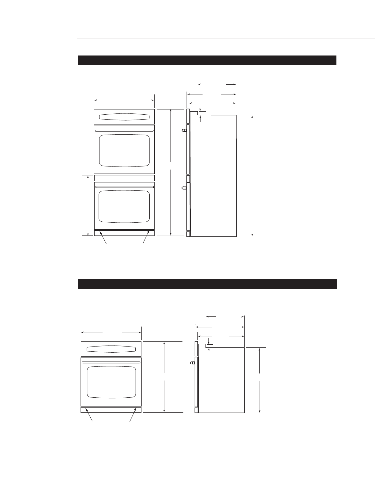
WALL OVEN DIMENSIONS
WOS-127 27” SINGLE WALL OVEN
WOS/WOSD-227 27” DOUBLE WALL OVEN
24-3/8"
26-7/8"
53-11/16"
26"
23-5/8"
1-9/16"
22-1/8"
51-5/16"
Bottom Trim screws
26-7/8"
Bottom Trim screws
Interior Dimension = 16"H x 22"W x 18-5/8"D
Rack Dimension = 21-3/8"W x 15"D
22-1/8"
24-3/8"
23-5/8"
1-9/16"
28-13/16"
Interior Dimension = 16"H x 22"W x 18-5/8"D
Rack Dimension = 21-3/8" W x 15"D
26-1/2"
Page 5
4
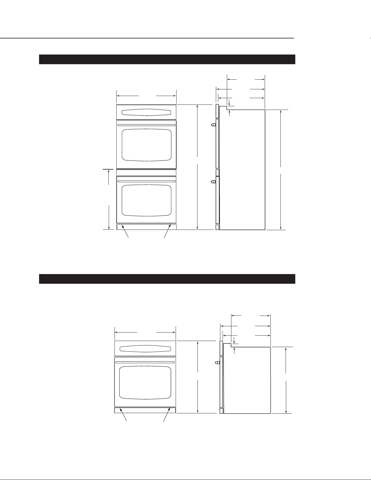
WALL OVEN DIMENSIONS
WOS/WOSD-230 30” DOUBLE WALL OVEN
WOS-130 30” SINGLE WALL OVEN
29-7/8"
1-9/16"
53-11/16"
26"
22-1/8"
24-3/8"
23-5/8"
51-5/16"
Bottom Trim screws
Interior Dimension = 16"H x 25"W x 18-5/8"D
Rack Dimension = 24-3/8"W x 15"D
29-7/8"
28-13/16"
22-1/8"
24-3/8"
23-5/8"
1-9/16"
26-1/2"
Bottom Trim screws
Interior Dimension = 16"H x 25"W x 18-5/8"D
Rack Dimension = 24-3/8"W x 15"D
Page 6
5
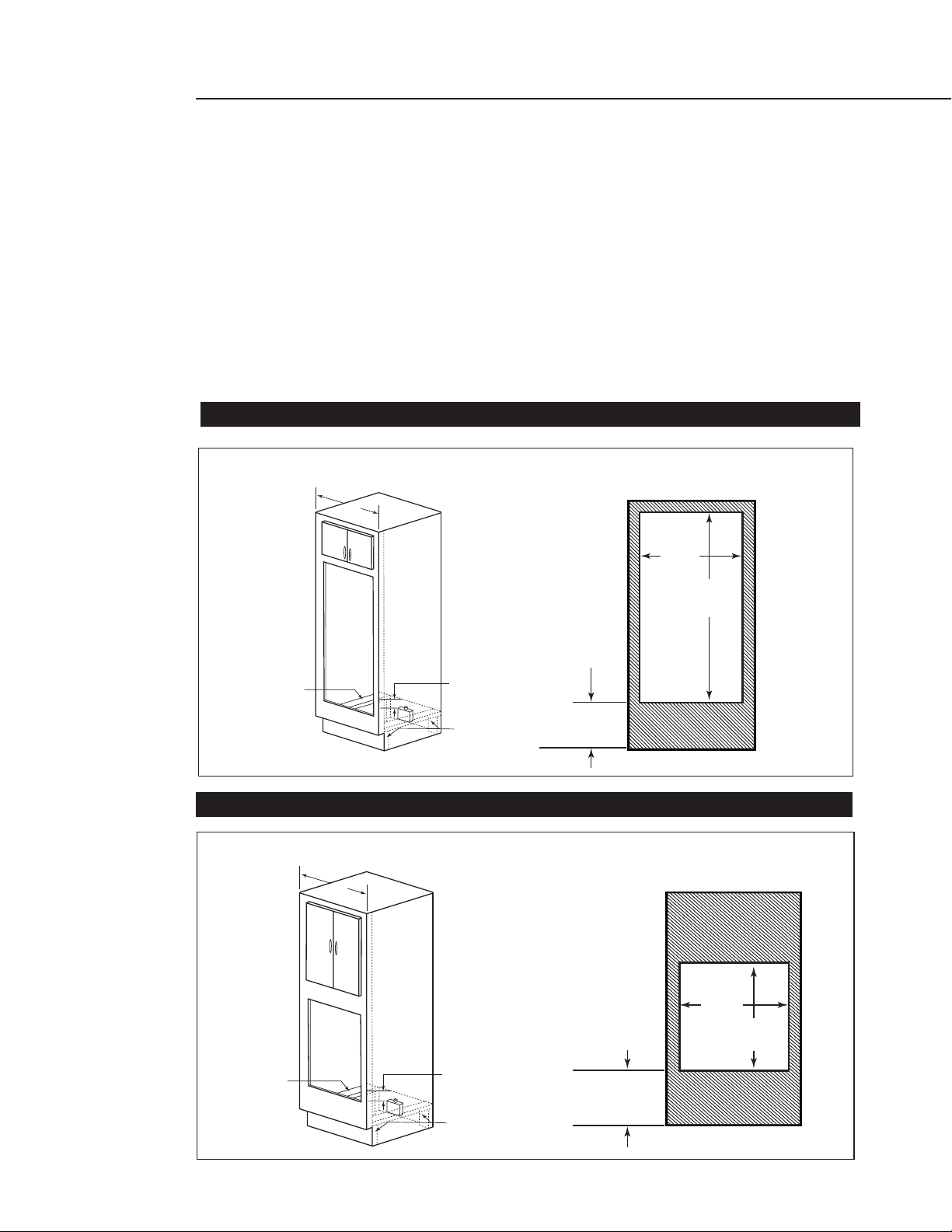
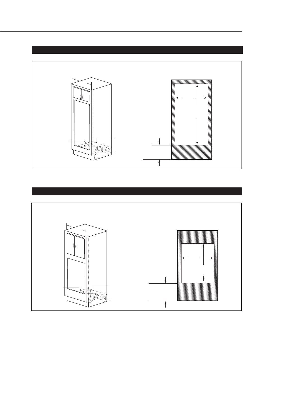
CABINET INSTALLATION
Our Ovens are designed to be installed into a 27” and 30” minimum width cabinet. For the best
appearance,to conceal the raw edges and to ensure a snug and secure fit,the cutouts must be precise.
Use the wall oven cutout dimensions provided for your installation. Ovens are very heavy, we suggest
two installers to lift ovens into the cabinet opening.
Cut 2”x 4” runners or create a solid shelf to support the oven unit at the bottom.
The bottom support must be level and capable of supporting the weight of the oven unit –
(i.e 445 pounds – double oven or 275 pounds – single oven.)
The electrical cable should be a 3 conductor or 4 conductor wire as required by local codes
(must be hard wired and dedicated).
U. L. Listed conduit connector required.
The conduit box is to be located in the center below the oven, 2 inches below the bottom.
Power supply wiring should be connected prior to installing the oven to the cabinet.
WAL L OVE N
Cut Out Dimensions
WAL L OVE N
Cabinet Dimensions
2x4's or
similar
runners
or solid
structure
support
Conduit
box centered
2" below bottom
of oven
2x4's or
similar supports
Floor
(Suggested
distance from
floor 12" min.)
27"
min.
25-1/2 "
53-1/4 "
+1/16"
- 0"
Floor
(Suggested
distance from
floor 20" min.)
WALL OVEN
Cut Out Dimensions
25-1/2 "
28-5/16 "
+1/16"
- 0"
Cabinet Dimensions
2x4's or
similar
runners
or solid
structure
support
Conduit
box centered
2" below bottom
of oven
2x4's or
similar supports
27"
min.
CABINET INSTALLATION
WOS/WOSD-227 27” DOUBLE WALL OVEN
WOS-127 27” SINGLE WALL OVEN
Page 7
6
NOTE: Do not use an extension cord with this appliance, the unit must be hard wired directly to the
electrical source.
CABINET INSTALLATION
WOS/WOSD-230 30” DOUBLE WALL OVEN
WOS-130 30” SINGLE WALL OVEN
2x4's or
similar
runners
or solid
structure
support
WAL L OVE N
Cabinet Dimensions
30"
min.
Conduit
box centered
2" below bottom
of oven
2x4's or
similar supports
(Suggested
distance from
floor 12" min.)
Floor
WAL L OVE N
Cut Out Dimensions
28-1/2 "
53-1/4 "
+1/16"
- 0"
WAL L OVE N
2x4's or
similar
runners
or solid
structure
support
Cabinet Dimensions
30"
min.
Conduit
box centered
2" below bottom
of oven
2x4's or
similar supports
(Suggested
distance from
floor 20" min.)
Floor
WAL L OVE N
Cut Out Dimensions
28-1/2 "
28-5/16 "
+1/16"
- 0"
Page 8
7
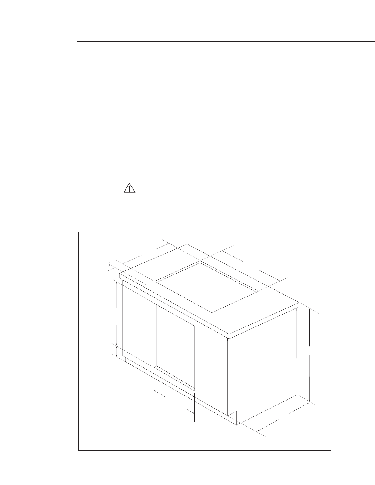
WOS-127 & 130 SINGLE WALL OVENS
The WOS-127 and WOS-130 single ovens may be installed below the DCS CT-365 gas cooktop in a
standard 36” tall (to counter surface) base cabinet. Refer to diagram shown below for cabinet and
countertop cutout dimensions.
The gas shut-off valve and power supply receptacle for the cooktop must remain accessible from the
front after the units are installed. It is suggested that the valve and receptacle be located in the
cabinet adjacent to the wall oven on the right. To prevent interference with the wall oven chassis,the
cooktop gas regulator must be mounted at the shut-off valve. Use approved flexible gas tubing to
make the connection between the regulator and the cooktop.
Install the cooktop into the countertop first. Make the connections to the gas and power supplies as
per the cooktop installation instructions. Verify that the electrical service to the oven is shut off. Make
the power supply connections for the wall oven and then slide the unit into the cabinet. Secure unit
to cabinet as noted in “Mounting the Wall Oven”section. Turn on all utilities and check both units for
proper operation.
WAR NING:
When pushing wall oven into cabinet, be careful not to pinch the gas
connection to the cooktop.
UNDER COUNTER INSTALLATION WITH CT-365
Cabinet Face
1-1/2"
Min.
28-5/16"
+ 1/16"
- 0"
4-3/4"
19-3/4"
25-1/2"
28-1/2"
34-3/4"
36"
(27" Oven)
(30" Oven)
24"
Page 9

8
Our built-in ovens require a dedicated and properly grounded 3-wire or 4-wire 120/240 volt, 60 Hz
power supply, protected by a time delay fuse or circuit breaker. Ovens are supplied with a flexible
power cable which must be attached to a junction box.
AMPERAGE:
WOS/WOSD-227& WOS/WOSD--230 = 50A WOS-127& WOS-130 = 30A
WARNING :
Electrical Shock Hazard!! Follow these instructions!
The electrical power to the oven branch circuit must be shut off while line connections are
being made.
Use the proper sized copper wiring only.
Electrical grounding is required on this appliance.The free end of the bare copper ground
wire must be connected to a suitable ground.This wire must remain grounded to the oven.
If cold water pipe is interrupted by plastic,non-metallic gaskets, union connections or other
insulating materials, DO NOT use for grounding.
DO NOT ground to a gas pipe.
DO NOT have a fuse in the Neutral or Grounding circuit. This could result in an electrical shock!
If you are in any doubt as to whether the appliance is properly grounded, check with a
qualified electrician.
FA ILURE TO FOLLOW THESE INSTRUCTION COULD RESULT IN SERIOUS INJURY OR DEATH!
MOUNTING THE WALL OVEN:
1) Remove all cardboard and packing materials.Remove the top wood pallet,bottom wood pallet
and metal mounting brackets. Remove the oven doors (see Use & Care manual page 18).
2) After creating your precision cabinet cutout and support and making power supply connection
as specified in this guide, with the oven in front of the cutout, slide the unit carefully into the
cabinet opening.
3) When in place, drill 3/32” holes into cabinet frame through mounting holes in the oven side
trim. See fig. 1.
4) Secure oven to cabinet with screws furnished as shown in figure 1 (uses 2 screws, 1 on each
side, top oven only).
5) Slip tabs on rear of bottom trim into mating slots in oven trim posts (see fig.2). Attach the
bottom trim with the 2 screws provided.
MOUNTING THE WALL OVENS
FIG. 2
FIG. 1
Page 10

9
SERVICE
HOW TO OBTAIN SERVICE:
For warranty service, contact your local DCS authorized service agency. Provide him/her with the
Model Number, Serial Number, and date of installation, and a brief description of the problem. If you
need assistance in locating the authorized service agency in your area please contact our DCS
Customer Service Representative for an authorized service agent near you, our number is
(888) 281-5698, Monday thru Friday, 6:00 am - 4:30 pm PST.
Your satisfaction is of the utmost importance to us. If a problem cannot be resolved to your
satisfaction, please write or email us at:
Write:
DCS
Attention: Customer Service
5800 Skylab Road
Huntington Beach, CA 92647
email: support@dcsappliances.com
BEFORE YOU CALL FOR SERVICE:
1. Is the circuit breaker tripped or the fuse blown?
2. Is there a power outage in the area?
3. Have you recently set the child safety mode? See page 17 for resetting in the Use and Care
Guide.
Page 11

WARRANTY
10
LENGTH OF WARRANTY
One (1) Year Full parts and Labor Covers the entire product.
Ten (10) Years Limited Porcelain oven, porcelain inner door panel.
DCS WILL PAY FOR
All repair labor and parts found to be defective due to materials or workmanship for one full year “IN
HOME” warranty from date of purchase. This does not apply if the unit was subjected to other than
normal household use. Service must be provided by Authorized Factory Technician during normal
working hours. No charges will be made for repair or replacement at the location of initial installation
or factory for parts returned pre-paid, through the dealer and claimed within the warranty period, and
found by DCS to be defective.
Replacement will be F.O.B. DCS, and DCS will not be liable for any transportation costs, labor costs,or
export duties. This warranty shall not apply, nor can we assume responsibility for damage that might
result from failure to follow manufactures instructions or local codes, where the appliance has been
tampered with or altered in anyway or which, in our judgement, has been subjected to misuse,
negligence, or accident.
DCS WILL NOT PAY FOR
Installation or start-up.
Shipping damage.
Service by an unauthorized agency.
Damage or repairs due to service by an unauthorized agency or the use of unauthorized parts.
Service during other than normal working hours.
Improper installation, such as improper hook-up,etc.
Service visits to teach you how to use the appliance; correct the installation; reset circuit
breakers or replace home fuses.
Repairs due to other than normal household use.
Damage caused from accident, abuse, alteration, misuse, incorrect installation or installation
not in accordance with local codes.
Units installed in non-residential application such as day care centers, bed and breakfast
centers, churches, nursing homes, restaurants, hotels, schools, etc.
This warranty applies to appliances used in residential applications; it does not cover their use in
commercial situations.
This warranty is for products purchased and retained in the 50 states of the U.S.A., the District of
Columbia and Canada. This warranty applies even if you should move during the warranty period.
Should the appliance be sold by the original purchaser during the warranty period, the new owner
continues to be protected until the expiration date of the original purchaser’s warranty period.
This warranty gives you specific legal rights. You may also have other rights which vary from state to
state.
This warranty is in lieu of all other warranties,express or implied, and all implied warranties, including
warranties of merchantability and fitness for a particular purpose, are hereby disclaimed to the full
extent permitted by law. To the extent that implied warranties may not be disclaimed,the duration of
any implied warranties, including implied warranties of merchantability and fitness for a particular
purpose, are limited to the duration of this express warranty. This warranty gives you specific legal
rights. You may also have other rights which vary from state to state.
Page 12

FOUR MURAL
Guide d'installation
MODÈLES :
WOS-227
WOS-230
WOSD-227
WOSD-230
WOS-127
WOS-130
Page 13

1
A L'INTENTION DE NOS CLIENTS
AV ER TI SSEMENT
To ute installation,ajustement, altération ou entretien incorrect peut causer des
dommages matériels, des blessures ou la mort.Veuillez lire soigneusement ces
instructions d'installation, d'utilisation et d'entretien avant d'utiliser, installer
ou effectuer l'entretien de cet appareil.
AV ER TI SSEMENT
Évitez de stocker ou d'utiliser de l'essence ou tous autres liquides et vapeurs
inflammables à proximité de cet appareil ou de tout autre appareil
électroménager.
AV ER TI SSEMENT RELATIF A LA SECURITE :
Coupez le circuit électrique au niveau du panneau de service et
verrouillez le panneau avant de brancher cet appareil électroménager.
Alimentation : Circuit de branchement de 120/240 V c.a., 60 Hz, 50 A
4 fil.
AV ER TI SSEMENT
NE VERSEZ PAS d'eau sur les feux de graisse. Éteignez le four mural, puis
étouffez le feu avec du bicarbonate de soude ou à l'aide d'un extincteur
à poudre ou à mousse.
VEUILLEZ CONSERVER CE MANUEL À TITRE DE RÉFÉRENCE.
Nous vous remercions d'avoir choisi ce four mural professionnel DCS.Nous avons conçu ce Manuel d'installation pour expliquer ses fonctions uniques. Il contient des informations extrêmement utiles sur la façon
d'installer correctement votre nouvel appareil. Vous pourrez ainsi en profiter pendant des années en toute
sécurité.
Si vous avez des questions au sujet de notre produit, communiquez avec un représentant du Centre de
service à la clientèle DCS par téléphone : 1-888-281-5698, du lundi au vendredi, de 6 h à 16 h 30, heure
normale du Pacifique,courriel : support@dcsappliances.com
ou par courrier :
DCS
Attention: Customer Service
5800 Skylab Road
Huntington Beach, CA 92647
Page 14

2
TABLE DES MATIERES
DIMENSIONS DU FOUR MURAL
Fours doubles WOS-227 27 po...........................................................................................................................3
Fours simples WOS-127 27 po............................................................................................................................3
Fours doubles WOS-230 30 po...........................................................................................................................4
Fours simples WOS-130 30 po............................................................................................................................4
INSTALLATION EN ARMOIRE
Fours doubles WOS/WOSD-227 27 po............................................................................................................5
Fours simples WOS-127 27 po............................................................................................................................5
Fours doubles WOS/WOSD-230 30 po............................................................................................................6
Fours simples WOS-130 30 po............................................................................................................................6
INSTALLATION SOUS COMPTOIR
Fours simples WOS-127 et 130...........................................................................................................................7
MONTAGE DU FOUR MURAL.............................................................................................................8
POUR L'OBTENTION DE SERVICE.....................................................................................................9
GARANTIE ....................................................................................................................................................................
10-11
Page 15

3
DIMENSIONS DU FOUR MURAL
FOUR SIMPLE WOS-127 27 PO
66 cm
FOUR DOUBLE WOS/WOSD-227 27 PO
56 cm
62 cm
68 cm
136 cm
60 cm
4 cm
130 cm
Vis de garniture inférieure
68 cm
Vis de garniture inférieure
Dimensions intérieures (H x l x p) = 40,6 x 55,9 x 47,3 cm
Dimensions de grille (l x p) = 54,3 x 38,1 cm
56 cm
62 cm
60 cm
4 cm
73 cm
Dimensions intérieures (H x l x p) = 40,6 x 55,9 x 47,3 cm
Dimensions de grille (l x p) = 54,3 x 38,1 cm
67 cm
Page 16

4
DIMENSIONS DU FOUR MURAL
FOUR DOUBLE WOS/WOSD-230 30 PO
FOUR SIMPLE WOS-130 30 PO
62 cm
76 cm
136 cm
66 cm
60 cm
4 cm
56 cm
130 cm
Vis de garniture inférieure
Dimensions intérieures (H x l x p) = 40,6 x 55,9 x 47,3 cm
76 cm
Vis de garniture inférieure
Dimensions intérieures (H x l x p) = 40,6 x 55,9 x 47,3 cm
Dimensions de grille (l x p) = 62 x 38,1 cm
56 cm
62 cm
60 cm
4 cm
73 cm
Dimensions de grille (l x p) = 62 x 38,1 cm
67 cm
Page 17

5
Nos fours sont conçus pour être installés dans une armoire d'une largeur minimum de 68,6 et 76,2 cm
(27 et 30 po). Pour donner une belle apparence à l'appareil,les découpes doivent être précises afin d'en
dissimuler les bords bruts et de permettre un ajustement serré et solide. Utilisez les dimensions de
découpe pour four mural fournies pour votre installation. Comme les fours sont très lourds, nous
suggérons que deux installateurs se chargent de les soulever et les placer dans l'ouverture de l'armoire.
Coupez des pièces d'appui 2 x 4 ou construisez une étagère solide pouvant supporter le four au
fond.
Le support inférieur doit être de niveau et capable de supporter le poids du four -
(c.-à-d.202 kg/445 livres - four double ou 125 kg/275 livres - four simple).
Le câble électrique doit comporter un fil à 3 ou 4 conducteurs conformément à la
réglementation en vigueur (doit être câblé et dédié).
Raccord de conduit homologué UL requis.
La boîte de raccordement doit être située au centre sous le four, à 5 cm (2 pouces) en dessous de
sa partie inférieure.
Le câblage d'alimentation doit être connecté avant l'installation du four dans l'armoire.
FOUR MURAL
Dimensions de découpe
FOUR MURAL
Dimensions de l'armoire
2x4 ou
pièces
d'appui
similaires
ou support
solide de
structure
Boîte de
raccordement
centrée 5 cm (2 po)
en dessous de la
partie inférieure
du four
2x4 ou
supports
similaires
Plancher
(Distance
suggérée à
partir du
plancher 30,5
cm/12 po min.)
68,6 cm
min.
64,8 cm
135,3 cm
+1,5 mm
-0 cm
Plancher
(Distance
suggérée à
partir du
plancher 50,8
cm/20 po min.)
FOUR MURAL
Dimensions de découpe
64,8 cm
71,9 cm
+1,5 mm
-0 cm
Dimensions de l'armoire
2x4 ou
pièces
d'appui
similaires
ou support
solide de
structure
Boîte de
raccordement
centrée 5 cm (2 po)
en dessous de la
partie inférieure
du four
2x4 ou
supports similaires
68,6 cm
min.
FOUR DOUBLE WOS/WOSD-227 27 PO
FOUR SIMPLE WOS-127 27 PO
INSTALLATION EN ARMOIRE
Page 18

6
REMARQUE : N'utilisez pas de rallonge avec cet appareil. Celui-ci doit être câblé directement à la
source électrique.
INSTALLATION EN ARMOIRE
FOUR DOUBLE WOS/WOSD-230 30 PO
FOUR SIMPLE WOS-130 30 PO
2x4 ou
pièces
d'appui
similaires
ou support
solide de
structure
FOUR MURAL
Dimensions de l'armoire
76,2 cm
min.
Boîte de
raccordement
centrée 5 cm (2 po)
en dessous de la
partie inférieure
du four
2x4 ou
supports
similaires
(Distance
suggérée à
partir du
plancher 30,5
cm/12 po min.)
Plancher
FOUR MURAL
Dimensions de découpe
72,4 cm
135,3 cm
+1,5 mm
-0 cm
FOUR MURAL
2x4 ou
pièces
d'appui
similaires
ou support
solide de
structure
Dimensions de l'armoire
76,2 cm
min.
Boîte de
raccordement
centrée 5 cm (2 po)
en dessous de la
partie inférieure
du four
2x4 ou
supports similaires
(Distance
suggérée à
partir du
plancher 30,5
cm/12 po min.)
Plancher
FOUR MURAL
Dimensions de découpe
72,4 cm
71,9 cm
+1,5 mm
-0 cm
Page 19

7
FOURS SIMPLES WOS-127 ET 130
Les fours simples WOS-127 et WOS-130 peuvent être installés sous la table de cuisson à gaz DCS CTR-365
dans un placard sur plancher standard de 36 po de haut (jusqu'à la surface du comptoir).Reportez-vous au
schéma ci-dessous concernant les dimensions de découpe du placard sur plancher et du comptoir.
Le robinet d'arrêt de l'alimentation de gaz et le bloc d'alimentation de la table de cuisson doivent rester
accessibles par l'avant une fois les appareils installés.Nous vous conseillons de les placer dans le placard
adjacent au four mural sur la droite.Pour éviter toute interférence avec le châssis du four mural,installez le
régulateur de gaz de la table de cuisson au niveau du robinet d'arrêt. Effectuez la connexion entre le
régulateur et la table de cuisson à l'aide d'un tuyau à gaz flexible homologué.
Installez la table de cuisson sur le comptoir en premier. Effectuez les raccords au gaz et au dispositif
d'alimentation conformément aux instructions d'installation de la table de cuisson. Vérifiez que l'alimentation électrique du four est coupée. Effectuez les connexions d'alimentation du four mural, puis glissez
l'appareil dans le placard. Fixez l'appareil au placard tel qu'indiqué dans la section « Montage du four
mural ». Activez toutes les sources d'alimentation et vérifiez le bon fonctionnement de chaque appareil.
AV ER TI SSEMENT :
Lorsque vous enfoncez le four mural dans le placard,faites attention de ne pas
pincer la connexion à gaz de la table de cuisson.
INSTALLATION SOUS COMPTOIR AVEC CT-365
Face d'armoire
3,8 cm
Min.
71,9 cm
+1,5 mm
- 0 cm
12 cm
50,2 cm
88,3 cm
91,4 cm
64,8 cm
72,4 cm
(Four 27 po)
(Four 30 po)
61 cm
Page 20

8
Nos fours encastrés nécessitent une alimentation électrique dédiée et correctement mise à la terre à 3 ou 4
fils de 120/240 V, 60 Hz protégée par un fusible ou disjoncteur temporisé. Les fours sont fournis avec un
câble d'alimentation flexible qui doit être branché à une boîte de jonction.
INTENSITE :
WOS/WOSD-227 et WOS/WOSD-230 = 50A WOS-127 et WOS-130 = 30A
AV ER TI SSEMENT :
Risque de choc électrique!! Suivez les instructions ci-dessous!
Coupez le courant électrique alimentant le circuit de branchement du four pendant que vous
effectuez toutes les connexions.
Utilisez uniquement un câblage de cuivre de diamètre approprié.
Cet appareil électroménager nécessite une mise à la terre électrique. L'extrémité libre du fil de terre
en cuivre nu doit être connectée à une terre adéquate.Ce fil doit rester mis à la terre sur le four.
ÉVITEZ d'utiliser le tuyau d'eau froide comme prise de terre s'il est interrompu par des joints non
métalliques en plastique,des connexions-unions ou d'autres matériaux isolants.
N'UTILISEZ PAS le tuyau de gaz comme prise de terre.
NE PLACEZ PAS de fusible dans le circuit neutre ou de terre. Cela pourrait provoquer un choc
électrique!
Consultez un électricien qualifié si vous avez des doutes concernant la mise à la terre de l'appareil.
LE FAIT DE NÉGLIGER CES INSTRUCTIONS PEUT ENTRAÎNER DES BLESSURES GRAVES OU MÊME
LA MORT!
MONTAGE DU FOUR MURAL :
1) Retirez tous les cartons et le matériel d'emballage. Retirez la palette de bois supérieure et inférieure,
et les supports de montage métalliques. Retirez les portes du four (voir le manuel d'utilisation et
d'entretien à la page 18).
2) Après avoir créé de façon précise la découpe et le support de l'armoire et effectué les connexions
d'alimentation tel que spécifié dans ce manuel, placez le four devant la découpe puis glissez
l'appareil soigneusement dans l'ouverture de l'armoire.
3) Une fois l'appareil en place,percez des trous de 2,4 mm (3/32 po) dans le cadre de l'armoire à travers
les trous de montage de la garniture latérale du four. Voir fig.1.
4) Fixez le four à l'armoire à l'aide des vis fournies tel qu'indiqué à la figure 1 (utilisez 2 vis,1 de chaque
côté, sur four du haut seulement).
5) Glissez les languettes à l'arrière de la garniture inférieure dans les fentes correspondantes des tiges
de la garniture du four (voir fig.2). Fixez la garniture inférieure à l'aide des 2 vis fournies.
MONTAGE DES FOURS MURAUX
Page 21

9
SERVICE
POUR L'OBTENTION DE SERVICE :
Pour le service sous garantie, contactez le centre de service DCS agréé le plus proche. Fournissez le
numéro de modèle, le numéro de série, la date d'installation ainsi qu'une brève description du
problème. Si vous avez besoin d'aide pour localiser les centres de service agréés de votre région,
veuillez communiquer avec le centre de service à la clientèle DCS qui vous indiquera l'agent agréé le
plus proche. Pour nous joindre :(888) 281-5698, du lundi au vendredi, de 6 h à 16 h 30, heure normale du
Pacifique.
Votre satisfaction revêt la plus haute importance pour nous. Si un problème n'est pas résolu à votre
entière satisfaction, veuillez communiquer avec nous :
Écrivez-nous à l'adresse suivante :
DCS
Attention: Customer Service
5800 Skylab Road
Huntington Beach, CA 92647
email : support@dcsappliances.com
AVANT D'APPELER LE SERVICE TECHNIQUE :
1.Est-ce que le disjoncteur s'est déclenché ou que le fusible est grillé?
2.Y a-t-il une coupure de courant dans le secteur?
3. Avez-vous récemment mis le mode de sécurité pour enfant? Voir la page 17 du Manuel d'utilisation et d'entretien concernant la façon de le faire.
Page 22

10
GARANTIE
DUREE DE LA GARANTIE
Un (1) an sur tout le produit,pièces et main-d'œuvre (pièces et main-d'œuvre)
Dix (10) ans de garantie limitée sur le four en porcelaine et le panneau de porte intérieur en
porcelaine.
DCS COUVRE LES FRAIS SUIVANTS
Frais de main-d'œuvre et de réparation de pièces jugées défectueuses pour cause de vice de matière
ou de fabrication, et ce pendant une année complète avec garantie « À DOMICILE » pendant la
première année d'achat. Cette garantie ne s'applique pas si l'appareil a été soumis à une utilisation
autre qu'une utilisation domestique normale. Le service doit être fourni par un agent agréé de l'usine
durant les heures ouvrables normales. Il n'y aura pas de frais facturés pour les réparations ou
remplacements effectués sur le site de l'installation initiale ou en usine pour des pièces renvoyées port
payé, par l'intermédiaire du distributeur, pendant la période de garantie, et jugées défectueuses par
DCS.
Les remplacements sont effectués franco à bord DCS et DCS n'est pas responsable des frais de
transport, de main-d'œuvre ou des tarifs douaniers s'appliquant à l'exportation. Cette garantie ne
saurait s'appliquer,et nous n'assumons aucune responsabilité pour les dommages pouvant résulter du
fait de ne pas avoir respecté les consignes du fabricant ou des codes en vigueur, ou d'avoir trafiqué ou
altéré l'appareil de quelque façon, ou d'avoir,selon nous, soumis l'appareil à une mauvaise utilisation,
à de la négligence ou à un accident.
DCS NE COUVRE PAS LES FRAIS SUIVANTS :
Installation ou démarrage.
Dommages subis durant le transport.
Service effectué par un centre non agréé.
Dommages ou réparations causés par un service effectué par un centre non agréé ou par l'utili-
sation de pièces non autorisées.
Service effectué en dehors des heures ouvrables normales.
Mauvaise installation, telle qu'un branchement incorrect, etc.
Visites de service pour vous apprendre comment utiliser l'appareil, corriger l'installation,réarmer
les disjoncteurs ou remplacer les fusibles de la maison.
Réparations dues à une utilisation autre qu'une utilisation domestique normale.
Dommages causés par accident, abus,altération, mauvaise utilisation, installation incorrecte ou
installation non conforme aux codes en vigueur.
Appareils installés dans le cadre d'applications non résidentielles telles que garderies,auberges,
lieux de culte, maisons de soin, restaurants, hôtels, écoles, etc.
Cette garantie s'applique aux appareils utilisés dans des applications résidentielles.Elle ne couvre pas
les utilisations commerciales.
Cette garantie couvre les produits achetés et utilisés dans les 50 états des États-Unis, le District de
Columbia et au Canada. La garantie s'applique même si vous déménagez durant la période de
garantie. Si l'appareil est vendu par l'acheteur initial durant la période de garantie, le nouveau
propriétaire continue de bénéficier de la protection jusqu'à la date d'expiration de la période de
garantie de l'acheteur initial.
Page 23

GARANTIE
11
Cette garantie vous donne des droits juridiques spécifiques. Il se peut que vous ayez d'autres droits
pouvant varier d'une juridiction à l'autre.
Cette garantie remplace toute autre garantie, explicite ou implicite. En outre, toutes les garanties
implicites, y compris les garanties de qualité marchande ou d'adaptation à un usage particulier,
sont déclinées par la présente dans toute la limite permise par la loi. Dans la mesure où les
garanties implicites ne peuvent être déclinées, la durée des garanties implicites, y compris les
garanties implicites de qualité marchande ou d'adaptation à un usage particulier, est limitée à la
durée de cette garantie expresse.Cette garantie vous donne des droits juridiques spécifiques. Il se
peut que vous ayez d'autres droits pouvant varier d'une juridiction à l'autre.
Page 24

12
NOTES
Page 25

NOTES
13
Page 26

5800 Skylab Road, Huntington Beach, CA 92647
Tel:714.372.7000 • Fax: 714.372.7001
Customer Service: (888) 281-5698
www.dcsappliances.com
DCS améliore constamment ses produits et se réserve le droit
de modifier les spécifications ou la conception de ses produits
sans aucun préavis.
As product improvement is an ongoing process at DCS, we
reserve the right to change specifications or design without
notice.
P/N 17534 Rev.C
Litho in USA 06/2004
 Loading...