

DCS WOSU30, WOSV30, WODU30, WODV30 Installation Guide

INSTALLATION INSTRUCTIONS
Wall Oven
WOSU30/WOSV30 and
WODU30/WODV30 models
US CA
www.dcsappliances.com
590731C 08.15
1 SAFETY AND WARNINGS
242 lb
110 kg
oven
409 lb
models
DOUBLE
186 kg
WARNING!
Electrical shock hazard
Before carrying out any work on the electrical section of the appliance, it
must be disconnected from the mains electricity supply.
Connection to a good ground wiring system is absolutely essential and
mandatory.
Alterations to the domestic wiring system must only be made by a
qualified electrician
Failure to follow this advice may result in electrical shock or death.
WARNING!
Fire hazard
Do not use adapters, reducers, or branching devices to connect this
appliance to the mains power supply.
Failure to follow this advice may result in overheating, burning, or fire.
WARNING!
Cut hazard
Take care - some panel edges are sharp.
Failure to use caution could result in injury or cuts.
WARNING!
Very Heavy
Do not attempt to lift this product unassisted.
Lifting unassisted may cause serious injury.
IMPORTANT SAFETY INSTRUCTIONS!
Save these instructions for the local inspectors use.
To avoid hazard, follow these instructions carefully before installing or using this appliance.
Please make this information available to the person installing the appliance - doing so could
reduce your installation costs.
This oven is to be installed and connected to the electricity supply only by an authorized
person.
If the installation requires alterations to the domestic electrical system, call a qualified
electrician. The electrician should also check that the socket cable section is suitable for the
electricity drawn by the oven.
The oven must be grounded.
Installation must comply with your local building and electricity regulations.
This appliance must be installed and connected to the mains power supply only by a suitably
qualified person according to these installation instructions and in compliance with any
applicable local building and electricity regulations. Failure to install the appliance correctly
could invalidate any warranty or liability claims.
If the power supply cable is damaged, it must be replaced by the manufacturer, its service
agent or similarly qualified person in order to avoid a hazard.
A circuit breaker is recommended.
Do not use adaptors, reducers or branching devices to connect the oven to the mains
electricity supply, as they can cause overheating and burning.
Make sure the cavity is completely sealed with no gaps. This is to ensure the oven cooling
system functions correctly.
Electrical requirements
Connect oven with copper wire only.
Do not cut the conduit.
A U.L. listed conduit connector must be provided at the junction box.
Do not ground to a gas pipe.
Do not have a fuse in the grounding or neutral circuit.
Fuse both sides of the line.
A time delay fuse or circuit breaker is recommended. If using a time delay fuse, then fuse
both sides of the line.
Flexible armored cable from the appliance should be connected directly to the junction box.
Connect directly to the fused disconnect (or circuit breaker box) through flexible, armored or
non-metallic sheathed, copper cable (with grounding wire).
If codes permit and a separate grounding wire is used, it is recommended that a qualified
electrician determine that the grounding path and wire gauge are in accordance with local
codes.
oven
242 lb
models
SINGLE
110 kg
IMPORTANT!
SAVE THESE INSTRUCTIONS
The models shown in this installation guide may not be available in all markets and are subject to change at any time. For current details about model and specification availability in your country, please go to our
website www.dcsappliances.com or contact your local DCS by Fisher & Paykel dealer.
2
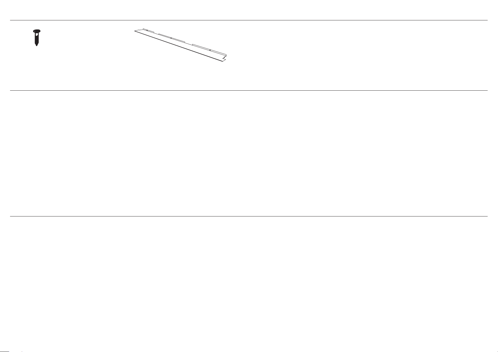
2 PARTS SUPPLIED
Screws
(2) for Single oven models
Long Trim (1)
(to be fitted in a flush installation)
(4) for Double oven models
Spacers
(2) for Single oven models
(4) for Double oven models
3 PRIOR TO INSTALLATION
The countertop and oven cavity are square and level, and are the required dimensions.
The installation will comply with all clearance requirements and applicable standards and regulations.
The isolating switch will be easily accessible to the customer with the oven installed.
The electrician provides sufficient free length of power supply cable to reach from the bottom rear of the cavity to at least 1.5 metres in front of the bottom edge of the opening.
The cable may enter the cavity from the side, top or bottom, but top entry must be at the rear of the cavity.
The oven connection socket (if fitted) is outside the cavity if the oven is flush to the rear wall.
The oven will rest on a surface that can support its weight.
The height from the floor suits the customer.
You consult local building authorities and by-laws if in doubt regarding installation.
IMPORTANT!
Some environmental factors and cooking habits can cause condensation in and around the oven during use. To protect surrounding cabinetry from possible damage caused by frequent or
excessive condensation, we recommend moisture-proofing the oven cavity.
4 AFTER INSTALLATION
IMPORTANT!
Please take extra care not to damage the lower trim of the oven during installation. The trim is important for correct air circulation and allows the door to open and close without obstruction.
The manufacturer does not accept any responsibility for damage resulting from incorrect installation.
The oven door(s) can open fully without obstruction.
Do not seal the oven into the cabinetry with silicone or glue. This makes future servicing difficult. DCS by Fisher & Paykel will not cover the costs of removing the oven, or of damage caused by this
removal.
The power supply cable does not touch any hot metal parts.
The isolating switch is easily accessible to the customer with the oven installed.
You complete the ‘Final checklist’ at the end of the installation.
If, after following the instructions given, correct performance cannot be achieved, please contact your nearest DCS by Fisher & Paykel Authorized Service Center, Customer Care, or contact us
through our local website listed on the cover of this document.
3
A
C F
B
E
G
H
D
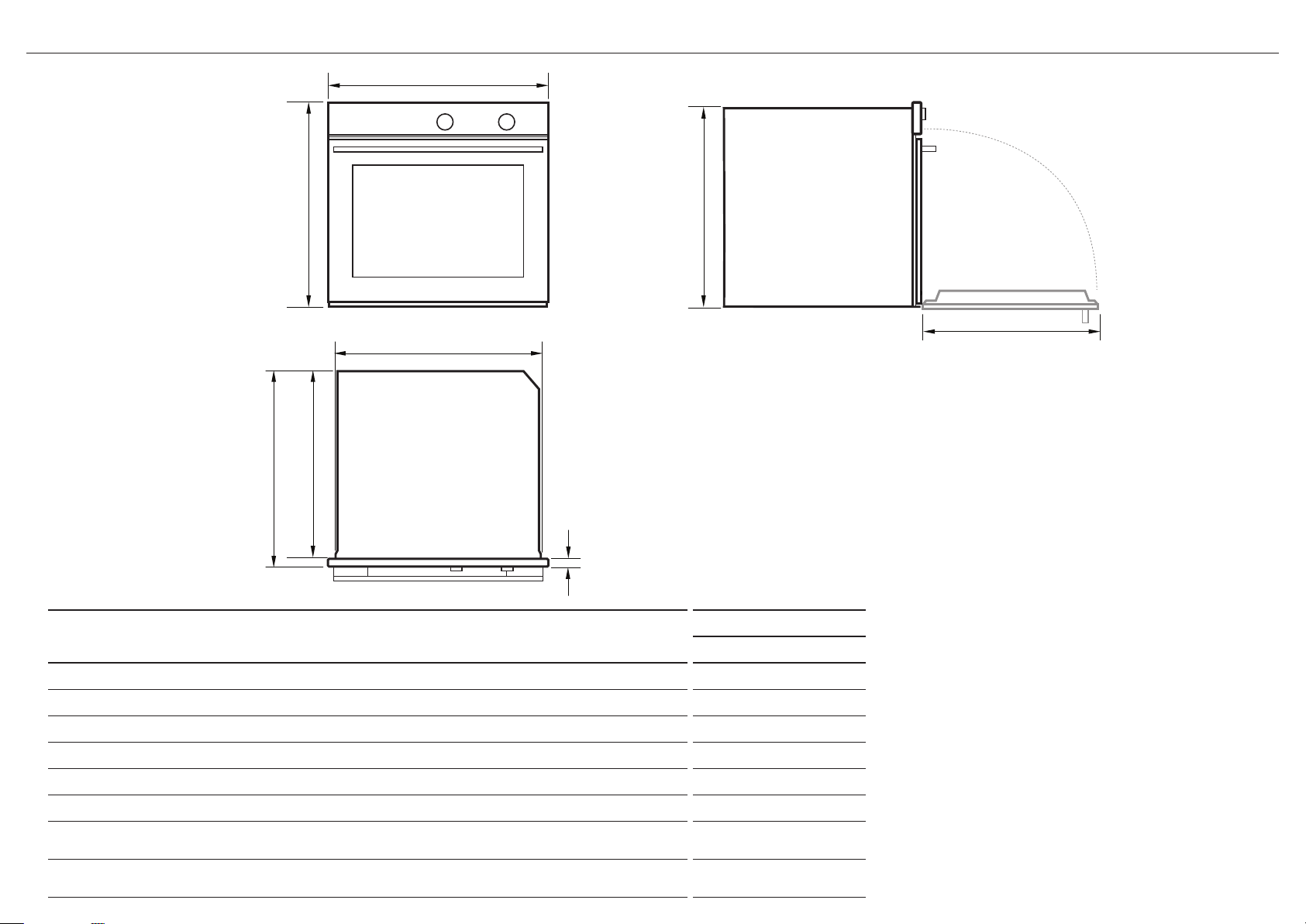
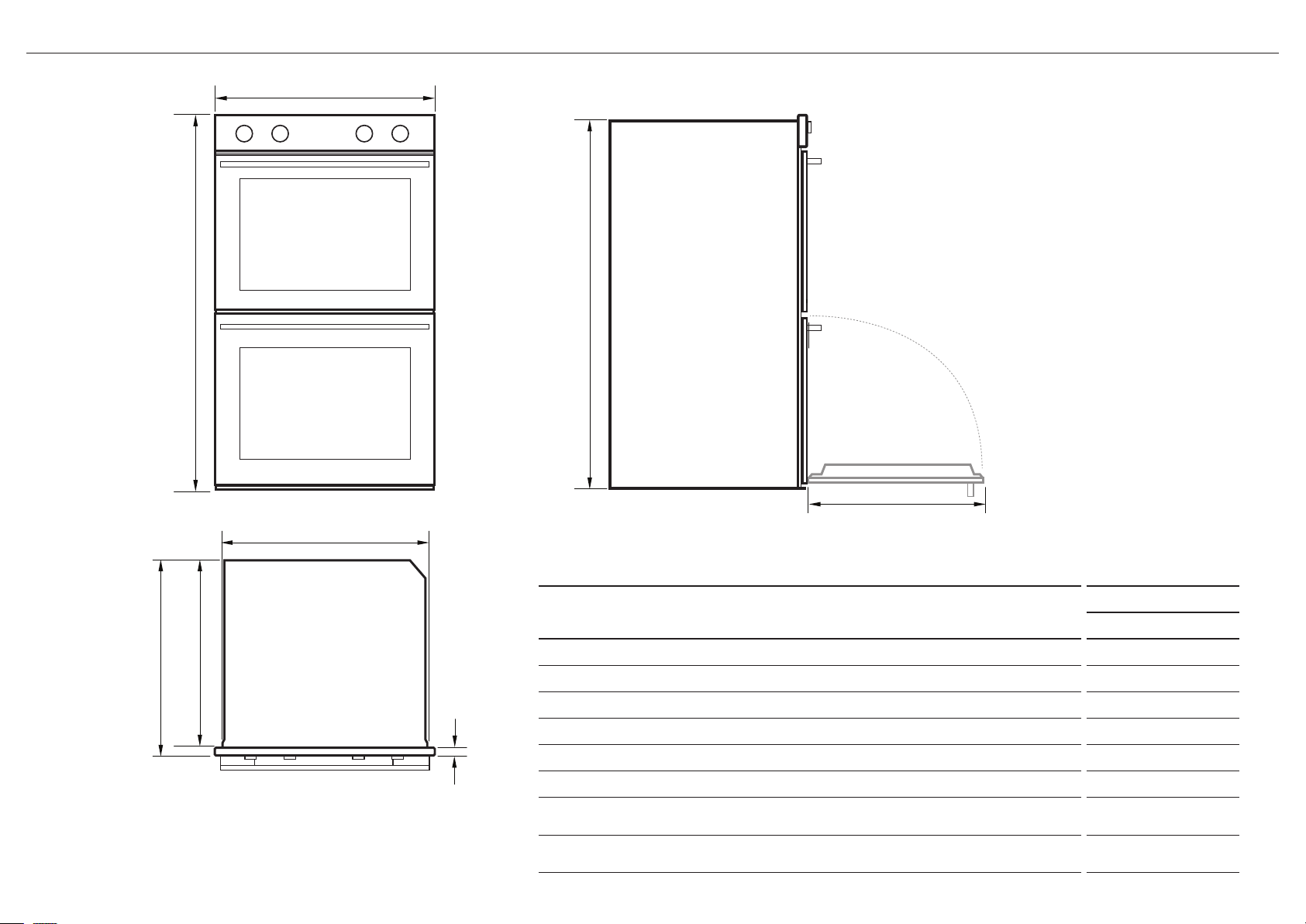
5 PRODUCT DIMENSIONS - SINGLE OVENS
PRODUCT DIMENSIONS
Overall height of product 27 1/8” (689)
A
Overall width of product 29 15/16” (760)
B
Overall depth of product (excluding handle and dials) 23 15/16” (608)
C
Height of chassis 26 9/16” (675)
D
Width of chassis 28 5/16” (720)
E
Depth of chassis 22 3/8” (569)
F
Depth of oven frame and control panel
G
(=distance between front of chassis and front of oven door, excl. knobs)
Depth of oven door when fully open
H
4
(measured from front of control panel)
FRONT
TOP
SIDE
WOSU30 WOSV30
INCHES (MM)
1 1/2” (39)
20 7/8” (530)
C F
E
G
H
I
J
K
L
M
Electrical supply
(16-20 mm)
5/8 - 13/16"
(16-20 mm)
5/8 - 13/16"
1-1/2"
1/16"
(2 mm)
min.
1/16"
(2 mm)
min.
(39 mm)
1-1/2"
(39 mm)
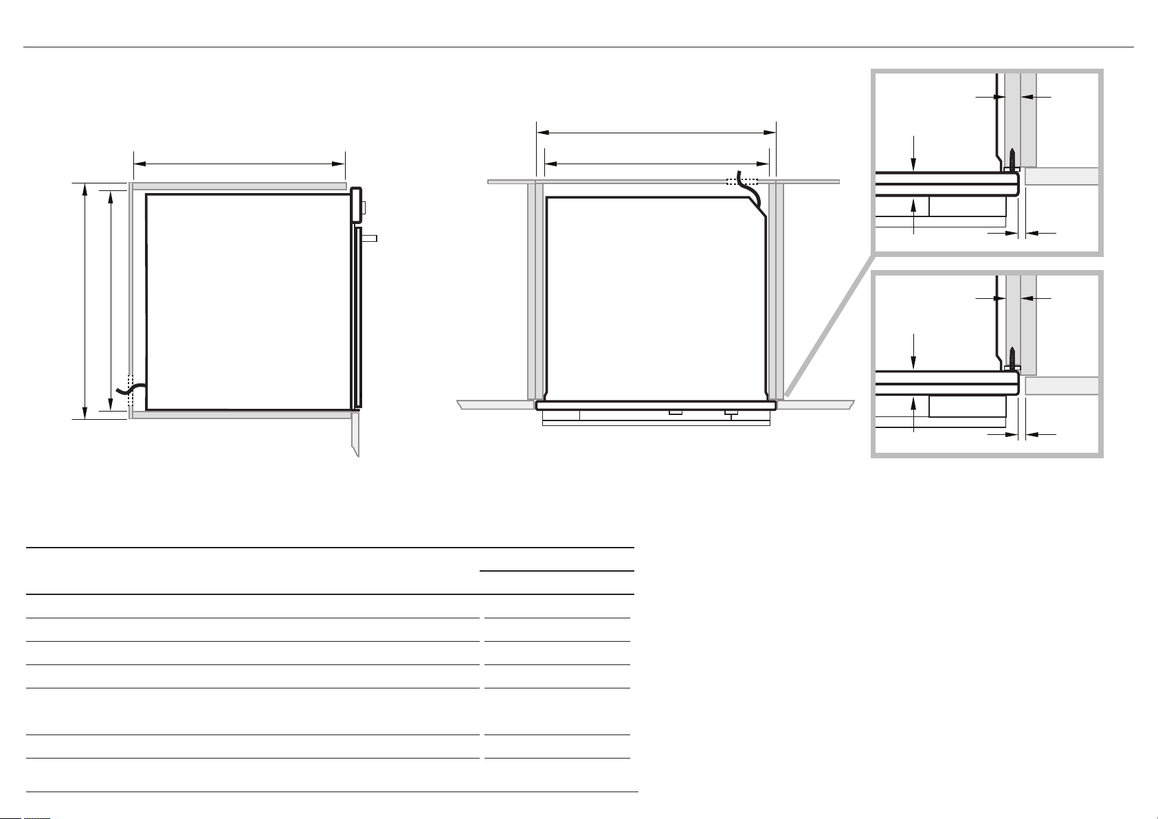
5 CABINETRY DIMENSIONS - SINGLE OVENS
PROUD INSTALL
CABINETRY DIMENSIONS
Minimum inside width of cavity 28 1/2” (724)
I
Overall width of cabinetry 30 1/8” (764)
J
Minimum inside height of cavity 26 13/16” (681)
K
Overall height of cabinetry 27 3/8” (693)
L
Minimum inside depth of cavity
M
Proud install
Flush install
Note: If installing a cooktop above the oven, ensure adequate clearance is provided for the cooktop as
per the cooktop manufacturer’s instructions.
SIDE
WOSU30 WOSV30
INCHES (MM)
22 5/8” (575)
24 1/8” (613)
TOP
FLUSH INSTALL
IMPORTANT!
FLUSH INSTALLATION
The depth of the control panel (G)
is larger than conventional ovens.
Ensure you have created a
1 1/2” (39 mm) recess in cabinetry.
If flush installing, you need to
replace the lower trim with the
supplied long trim at the base
of the oven. Refer to Step 11 for
instructions.
IMPORTANT!
Make sure the cavity is completely
sealed with no gaps.
This is to ensure the oven cooling
system functions correctly.
5
A
C F
B
E
G
H
D
16-20 mm
5 PRODUCT DIMENSIONS - DOUBLE OVENS
FRONT
TOP
SIDE
PRODUCT DIMENSIONS
Overall height of product 48 1/2” (1232)
A
Overall width of product 29 15/16” (760)
B
Overall depth of product (excluding handle and dials) 23 15/16” (608)
C
Height of chassis 47 15/16” (1218)
D
Width of chassis 28 5/16” (720)
E
Depth of chassis 22 3/8” (569)
F
Depth of oven frame and control panel
G
(=distance between front of chassis and front of oven door, excl. knobs)
Depth of oven door when fully open
H
(measured from front of control panel)
WODU30 WODV30
INCHES (MM)
20 7/8” (530)
1 1/2” (39)
6

C F
G
K
L
M
I
J
(16-20 mm)
5/8 - 13/16"
(16-20 mm)
5/8 - 13/16"
1-1/2"
1/16"
(2 mm)
min.
1/16"
(2 mm)
min.
(39 mm)
1-1/2"
(39 mm)
Electrical supply
5 CABINETRY DIMENSIONS - DOUBLE OVENS
PROUD INSTALL
SIDE
TOP
CABINETRY DIMENSIONS
Minimum inside width of cavity 28 1/2” (724)
I
Overall width of cabinetry 30 1/8” (764)
J
Minimum inside height of cavity 48 3/16” (1224)
K
Overall height of cabinetry 48 11/16” (1236)
L
Minimum inside depth of cavity
M
Proud install
Flush install
WODU30 WODV30
INCHES (MM)
22 5/8” (575)
24 1/8” (613)
FLUSH INSTALL
IMPORTANT!
FLUSH INSTALLATION
The depth of the control panel (G) is larger
than conventional ovens. Ensure you have
created a
1 1/2” (39 mm) recess in cabinetry.
If flush installing, you need to replace the
lower trim with the supplied long trim at
the base of the oven. Refer to Step 11 for
instructions.
IMPORTANT!
Make sure the cavity is
completely sealed with no gaps.
This is to ensure the oven
cooling system functions
correctly.
7
1
2
Single model shown for
illustration purposes only
Oven may vary
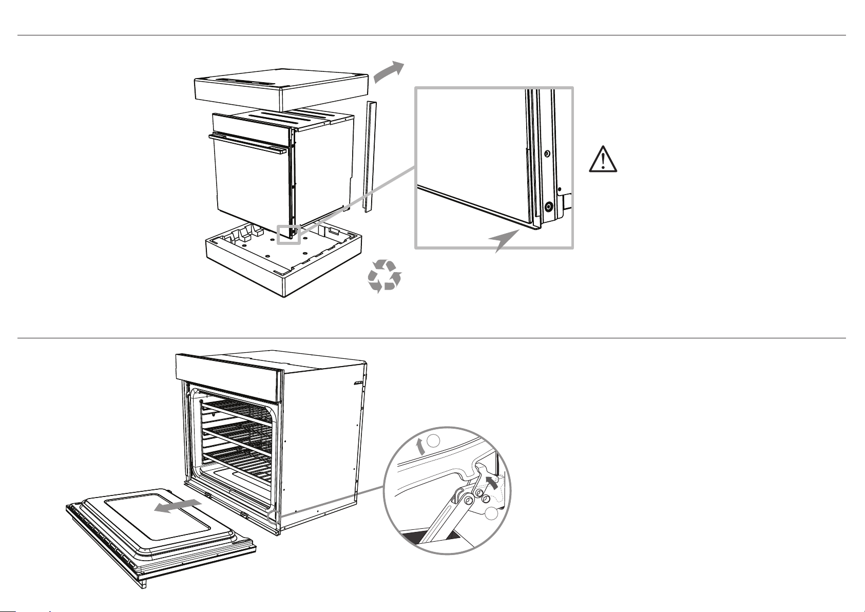
6 DISCARD PACKAGING RESPONSIBLY
Lower trim
Recycle responsibly
IMPORTANT!
When you remove the oven from the carton be
careful not to damage the lower trim. The trim is
important for both ventilation and to ensure the
door opens fully without obstruction.
Make sure you remove the Long Trim from the
packaging.
7 REMOVE THE DOOR(S)
IMPORTANT!
Do not lift the oven by the door handle.
1 Hook the door swivel retainers onto the metal bar above them.
2
1
8
2 Lift the oven door slightly to disengage the hinge.
3 Pull the door forward off the appliance and lie it on a flat
surface.
Double oven models only:
Remove both doors.
 Loading...