

Page 1

INSTALLATION INSTRUCTIONS
Framed Cabinetry
ActiveSmart™ Integrated Door Drawer Refrigerator
RS36W80 models
US CA
www.fisherpaykel.com
www.dcsappliances.com
844189 A 04.16
Page 2

Page 3
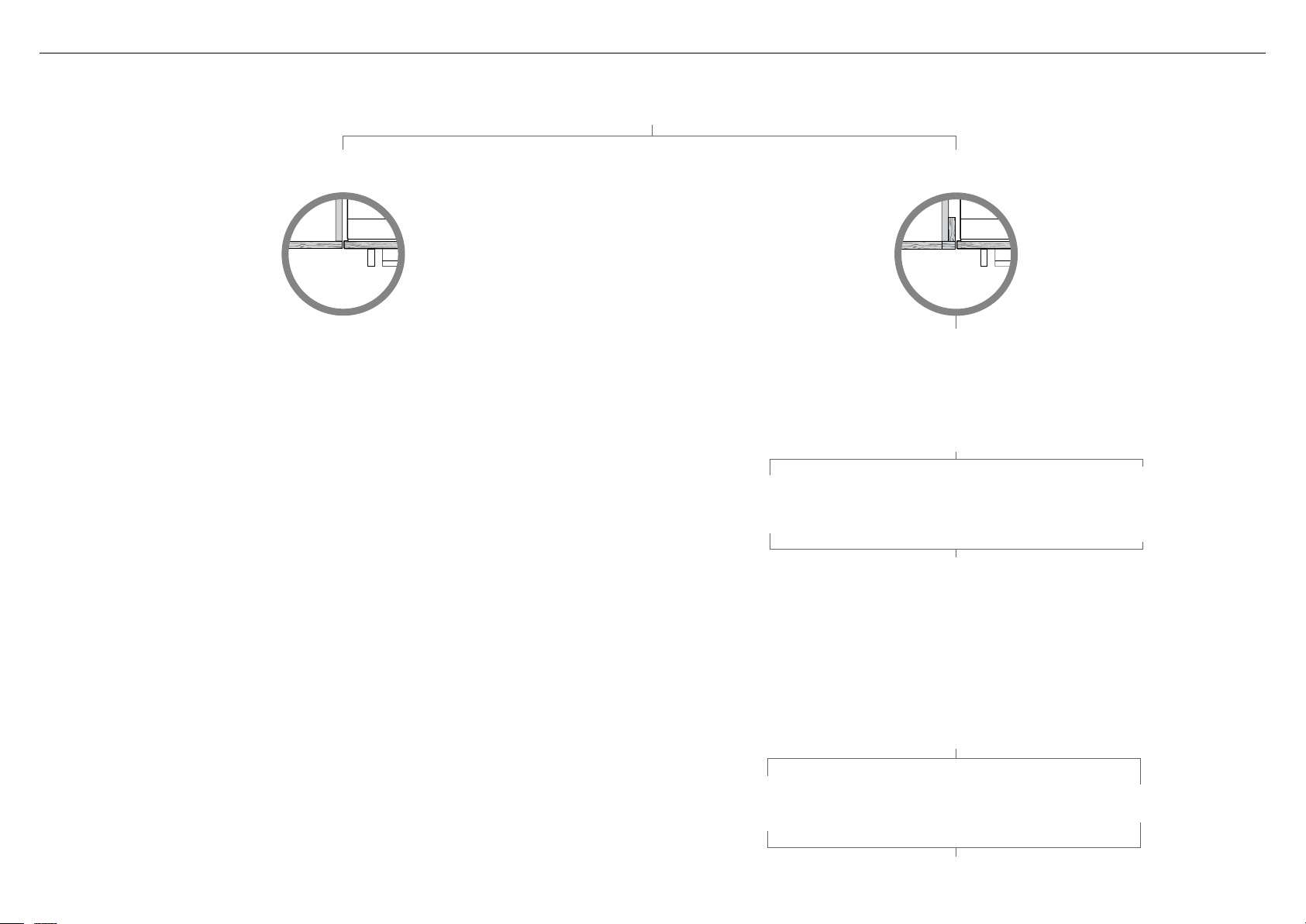
FOLLOW THE INSTALLATION SEQUENCE RELEVANT TO YOUR CABINETRY
NOTE: PRODUCT IS DESIGNED FOR FLUSH INSET INSTALLATION ONLY
FISHER & PAYKEL: RS36W80(R/L)J and RS36W80RU models
DCS: RS36W80(R/L)JC and RS36W80RUC models
FRAMELESS CABINETRY
(Frameless: Aligns the product with the cabinetry)
Note: shown with
custom panel and handles
attached to fridge
(refer to the flip side of the booklet)
(Framed: Aligns the product with the frame of the cabinetry)
4 MAXIMUM DISTANCE OF HOSE AND POWER CORD
8 80” CAVITY
(2032 mm)
ATTACH ANTI-TIP BRACKET
9
ATTACH SIDE BASE BRACKETS AND DOOR STUDS
!0 CONNECT TO WATER AND ELECTRICAL SUPPLY
!1 PRE-ALIGN YOUR PRODUCT INSIDE CABINETRY
!2 INSTALL WATER FILTER CARTRIDGE AND KICKSTRIPS
!5 HANG NON-WATER DISPENSING DOOR PANELS
FRAMED CABINETRY
Note: shown with
custom panel and handles
attached to fridge
1 SAFETY AND WARNINGS
2 BEFORE INSTALLATION
3 COMPONENTS LIST
5 PRODUCT AND CAVITY DIMENSIONS
6 CAVITY PREPARATIONS
7 CUSTOM DOOR PANEL DIMENSIONS
OR
!3 ASSEMBLE DOOR PANEL SET
!4 HANG ICE & WATER DOOR PANEL
!6 ICE AND WATER INITIATION
!7 ATTACH FIXING BRACKETS
!8 ATTACH COVERS AND TOE KICK
!9 ATTACH BOTTOM GRILLES
8 84” CAVITY
(2134 mm)
ATTACH ANTI-TIP BRACKET
ATTACH TOP TRIM
@0 ATTACH SIDE TRIM BRACKETS –
(A) FLEXIBLE SPRING CLIP METHOD
(Recommended method)
@1 ADJUST HINGE TENSIONING SCREWS
OR
@2 FINAL CHECKLIST
@0 ATTACH SIDE TRIM BRACKETS –
(B) FIXED SCREW METHOD
1
Page 4

Page 5
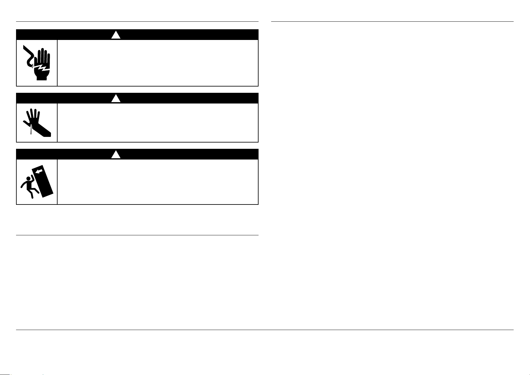
1 SAFETY AND WARNINGS
2 BEFORE INSTALLATION
!
WARNING!
Electric Shock Hazard
Read and follow the safety and warnings outlined in this installation
instructions guide before operating this appliance.
Failure to do so can result in death, electric shock, fire or injury
topersons.
!
WARNING!
Cut Hazard
Take care – panel edges are sharp. Failure to use caution could result in
injury or cuts.
!
WARNING!
This appliance is top-heavy and must be secured to prevent the
possibility of tippingforward.
To ensure that the appliance is stable under all loading conditions,
theanti-tip bracket and fittings supplied must be installed according
tothe following installation instructions by a professional installer.
Power
To ensure that the appliance is not accidentally switched off, connect your refrigerator to its
own isolating switch. Do not plug in any other appliance at this isolating switch.
For power requirements, please refer to the information on the serial plate. This is located
atthe front right-hand side of the drawer when open.
It is essential that the appliance is properly grounded (earthed).
Connect the appliance to the electrical supply (115VAC, 60Hz) with the fitted plug and lead.
Follow the National Electrical Code and all local codes and ordinances when installing
thisproduct.
Warning: Ground Fault Circuit Interrupters (GFCI) may trip during normal operation of your
refrigerator and interrupt the power supply. The use of a GFCI is not recommended with
thisproduct.
Location
Your refrigerator should not be located in direct sunlight or next to any heat generating
appliance such as a cooktop, oven or dishwasher.
Your product is fitted with front and rear rollers designed for moving the product in
forwards and backwards direction.
Avoid moving the product in a sideways direction as this may damage the rollers or the floor
covering/surface.
Plumbing
Your product must be installed by a qualified appliance installer as incorrect plumbing can
lead to water leaks.
Fisher & Paykel Appliances and DCS by Fisher & Paykel Appliances do not accept
responsibility for damage (including water damage) caused by faulty installation or plumbing.
Door panel set
2 BEFORE INSTALLATION
Please follow the installation steps specified to ensure your appliance is installed and
operatescorrectly.
The standard appliance does not include a door panel set.
Custom door panels can only be used with non-Water dispensing models.
For a custom integrated design on non-Water dispensing models, customers would supply
their own custom door panel set to match their cabinetry. All the hardware required to
mount the door panel sets to the refrigerator doors is supplied with the appliance.
Refrigeration alcove preparation
Door panel sets are available through your Fisher & Paykel dealer.
– Fisher & Paykel door panel sets are available (EZKleen stainless steel door panels) model
For integrated installation, a finished return of solid material is required across the top and
sides of the new or existing alcove.
It is recommended that the return be at least 3 1/2” (88.9mm) deep across the sides.
Refer to page13 prior to installation of the appliance.
numbers: RD3680(L/R), RD3680RU, RD3684(L/R) and RD3684RU.
– DCS door panel sets are available (stainless steel door panels) model numbers:
RD3680(L/R)C, RD3680RUC, RD3684(L/R)C and RD3684RUC.
Handle sets are optional for custom door panels and can also be purchased through your
Fisher & Paykel dealer.
IMPORTANT!
SAVE THESE INSTRUCTIONS
The models shown in this installation guide may not be available in all markets and are subject to change at any time. For current details about model and specification availability in your country, please go to
our website www.fisherpaykel.com or www.dcsappliances.com or contact your local Fisher & Paykel dealer.
3
Page 6
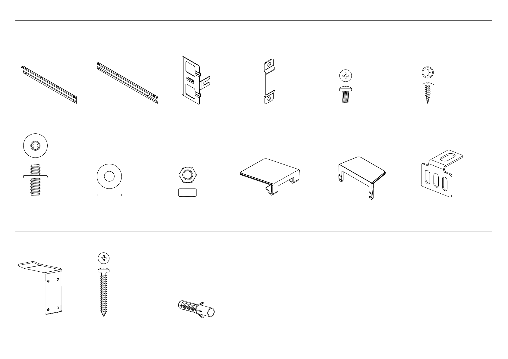
Door panel fittings – Included with standard appliance.
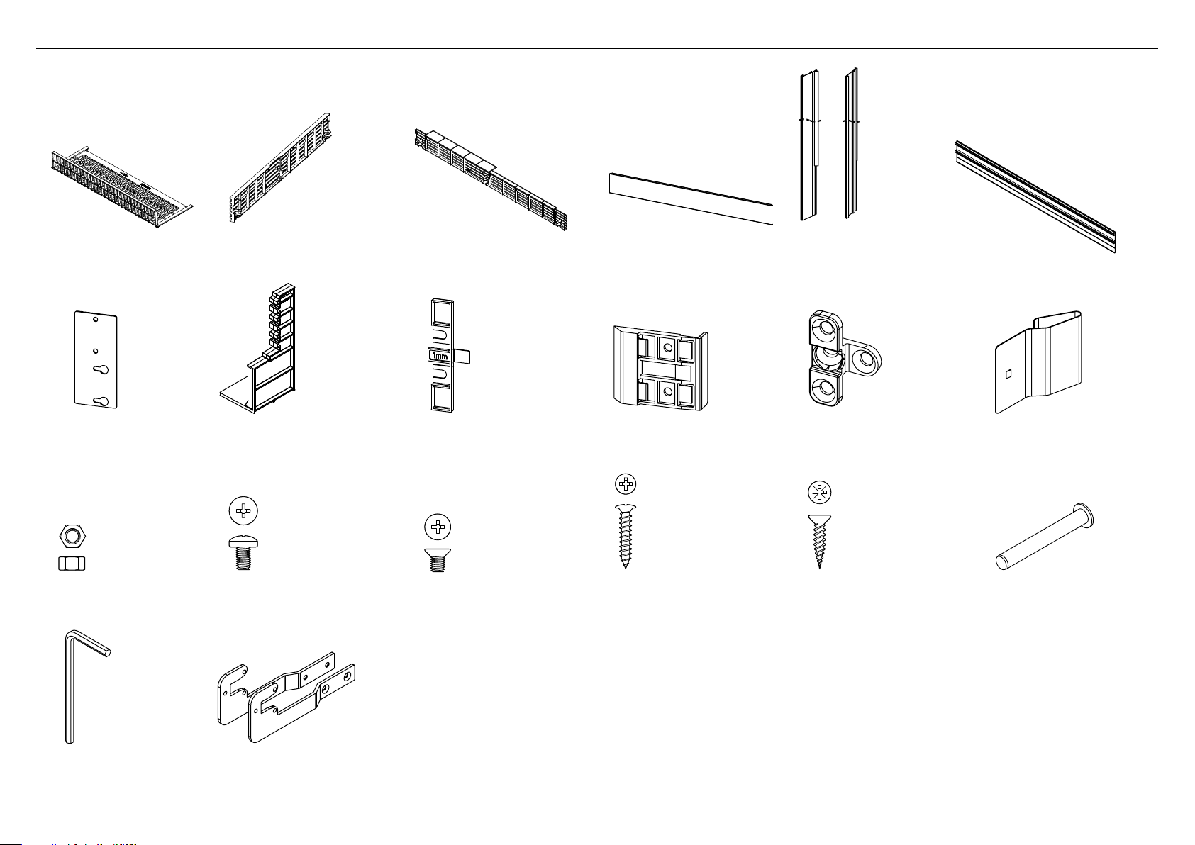
3 COMPONENTS LIST
Door hanging bracket
(1)
M8 stud
(5)
Anti-tip bracket fittings – Included with standard appliance.
Drawer hanging bracket
(1)
M8 washer
(4)
Side bracket
(6)
M8 nut
(4)
Side strap
(6)
Top cover
(2)
M5x10 pan head
Phillips screw
(6)
Side cover
(10)
#8 x 16 mush washer screw
(35)
((12) for Side trim attachment:
Fixed screw method only)
Locking bracket
(1)
Anti-tip bracket
(1)
4
#10x40 pan head
Phillips screw
(4)
Masonry plug
(4)
Page 7
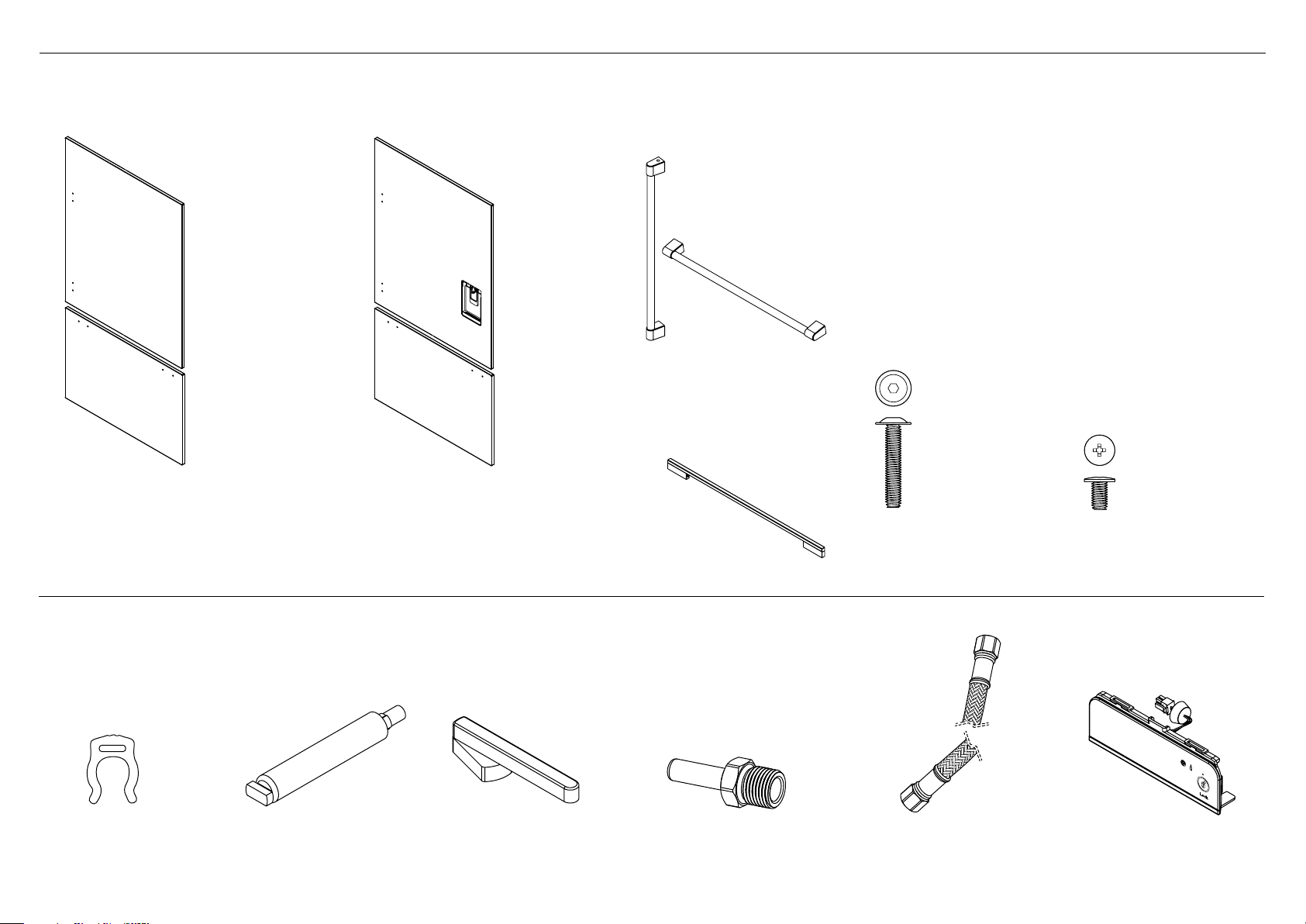
3 COMPONENTS LIST
Optional accessories – The standard appliance does not include a door panel set.
Fisher & Paykel (EZKleen stainless steel) and DCS (Stainless steel) door panel sets are available. For models with a water dispenser, the stainless steel door panel sets are required.
For complete integration of non-Water dispensing models a custom door panel set is required. Door handle kits are available as an accessory for custom door panels.
DCS: Door handle (1)
DCS: Drawer handle (1)
OR
Door panel set:
Non-Water dispensing door panel (1)
Drawer panel (1)
Part numbers:
F&P: RD3680(L/R) or RD3684(L/R)
DCS: RD3680(L/R)C or RD3684(L/R)C
Water fittings – Included with the standard appliance
Collet locking key
(1)
Water filter cartridge (1)
Part number: 81099
Door panel set:
Ice & Water door panel (1)
Drawer panel (1)
Part numbers:
F&P: RD3680RU or RD3684RU
DCS: RD3680RUC or RD3684RUC
Filter cartridge tool
(1)
F&P: Door handle (2)
1/4” (6mm) Adaptor
(1)
M5x25 pan head
socket screw
(8)
1/4” (6mm) comp.
Stainless Steel braided hose
(1)
M5x14 Mush Phillips SS
(34)
External display module (1)
(included with RS36W80U
and RS36W80UC DCS
standard appliance)
5
Page 8
Product hardware – Included with standard appliance.
3 COMPONENTS LIST
Kickstrip filter
(1)
Top trim joining bracket*
(2)
M5 nut
(4)
Top kickstrip grille
(1)
Air divider
(1)
M5 x 8 pan head
Phillips screw
(4)
Bottom kickstrip grille
(1)
Screw cover
(4)
M5 x 8 countersunk
Phillips screw
(12)
Stainless steel toe kick
(1)
Side trim bracket
(6)
#8 x 5/8” (16mm)
panhead screw
(3)
Side trim
(2)
Fixing bracket
(4)
#8 x 19 twin thread screw
(8)
Top trim*
(1)
Spring Clip (6)
(for Side trim attachment:
Flexible spring clip method
only)
Hinge limiting pin
(1)
Allen key
(1)
* To be used when finished enclosure is 84” (2134mm).
6
Side base bracket
(2)
Page 9
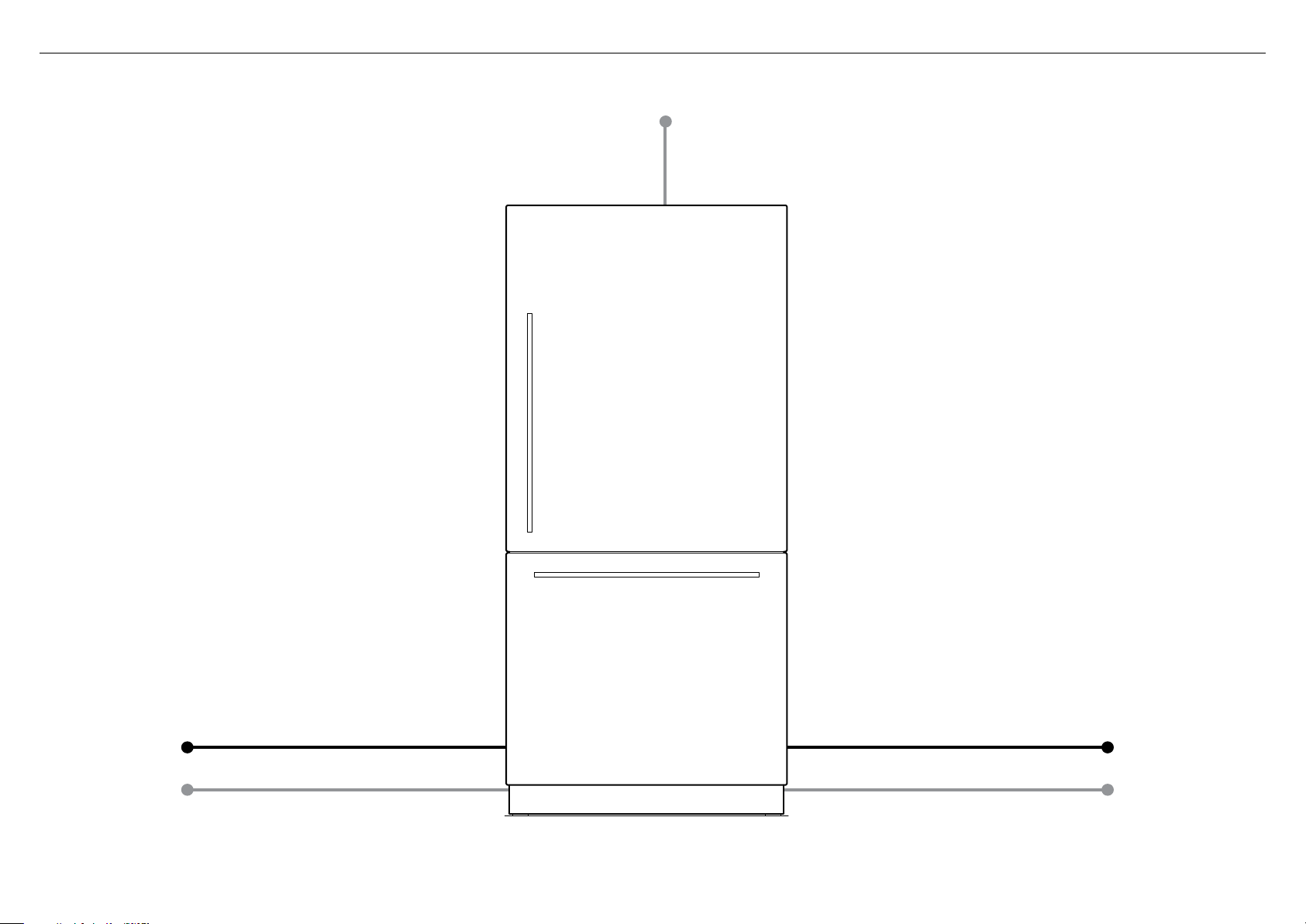
4 MAXIMUM DISTANCE OF HOSE AND POWER CORD
Power cord (excl. plug) – 31 1/2” (800mm)
LEFT HAND SIDE
Water inlet hose – 53” (1350mm) Water inlet hose – 84 1/4” (2120mm)
Power cord (excl. plug) – 80 3/4” (2051mm)
Power cord (excl. plug) – 80 3/4” (2051mm)
RIGHT HAND SIDE
7
Page 10
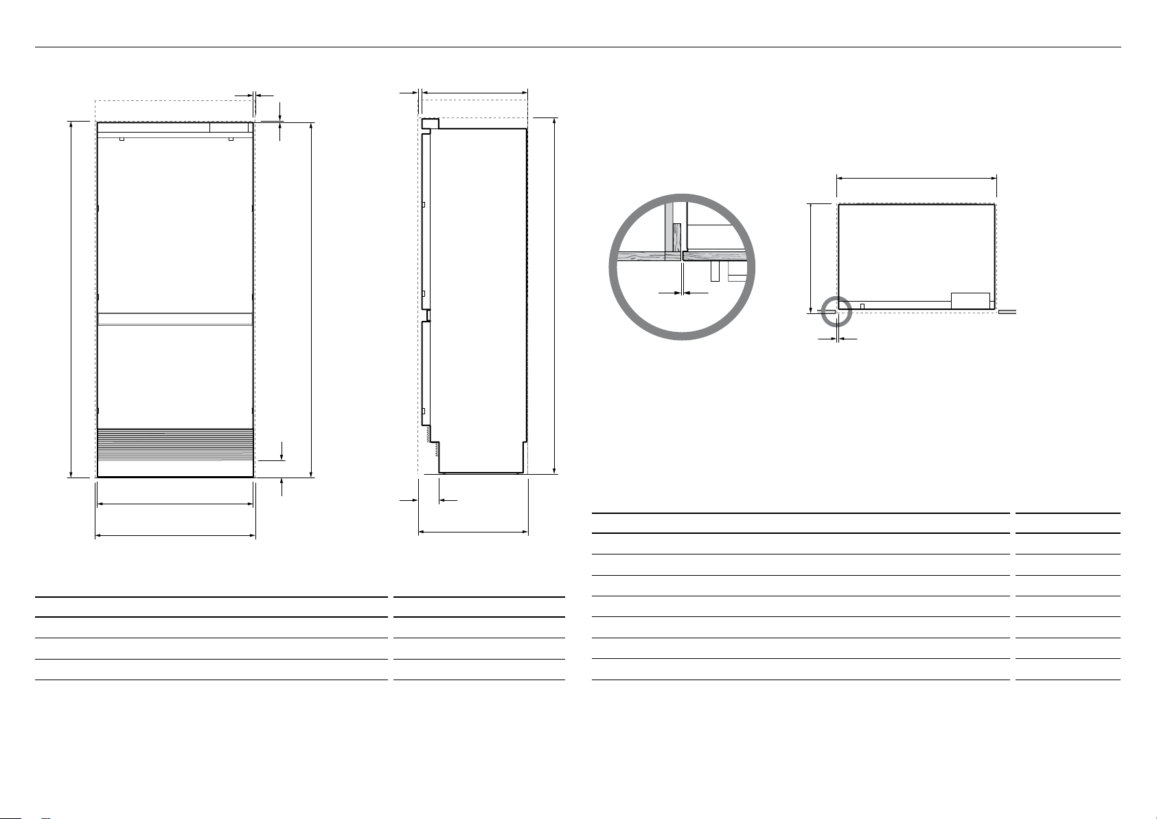
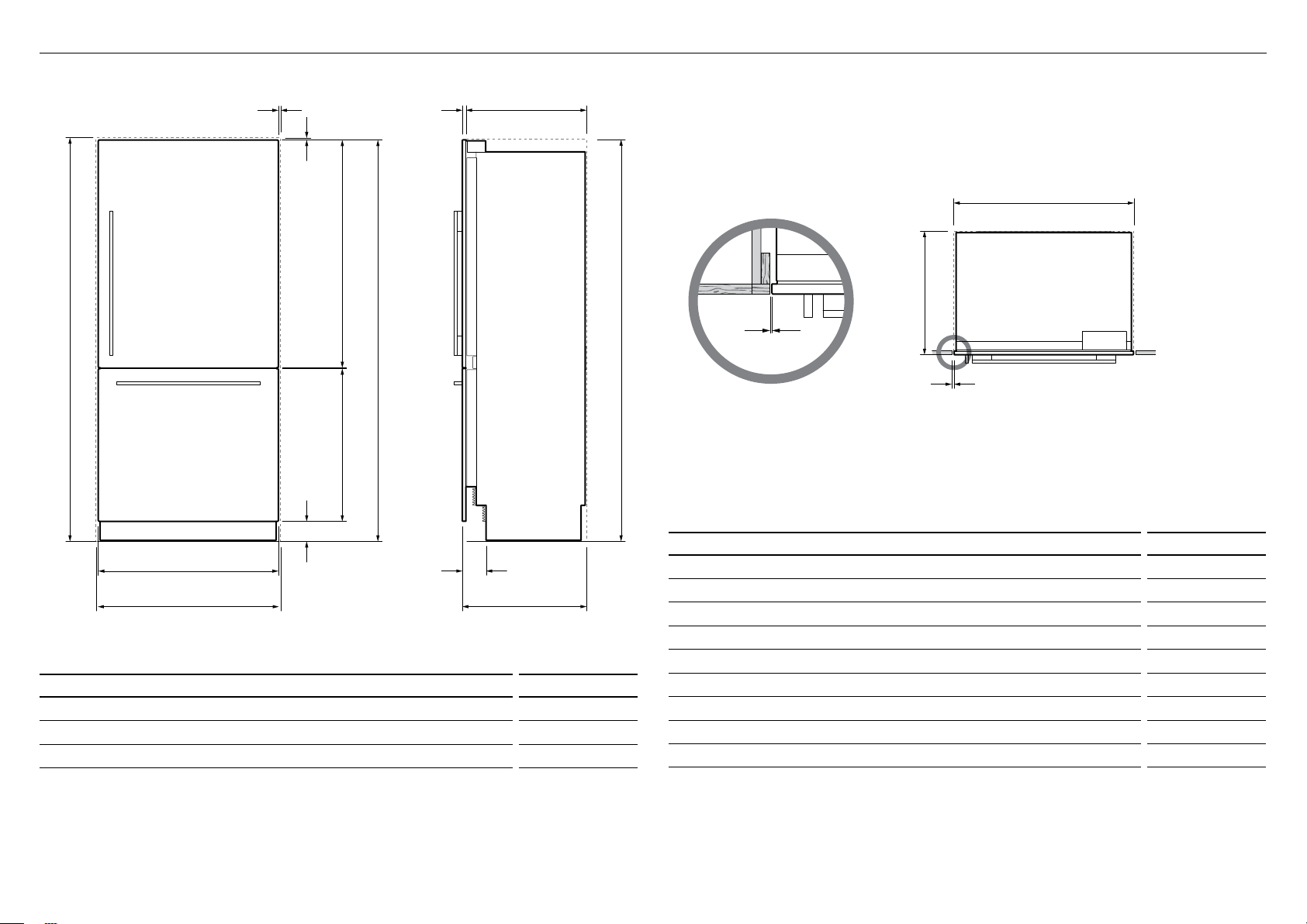
5 PRODUCT AND CAVITY DIMENSIONS
H
C
A
J G
C
B
F
D
AA
C
B
A
F
F
J G
5/32” (4mm)
Note: shown with custom
panel and handles attached
to fridge
C
F
B
Flush with front
of cabinetry
PLAN VIEW
E
I
B
CAVITY DIMENSIONS inches (mm)
Overall height of cavity 80 – 84” (2032 – 2134)
A
Overall width of cavity 36” (914)
B
Overall depth of cavity* 24 3/4” (629)
C
Total front panel width with required gaps at sides = 36” (914mm). (Refer to ‘Custom door panel dimensions’
section – panel width + 2 x
* Assumes a door panel thickness of 3/4” (19mm).
RS36W80RJ or RS36W80RJC DCS models shown only.
When designing custom door panels, these are only available for non-Water dispensing models.
8
F cabinetry gaps).
H
C
PROFILE VIEWFRONT VIEW
PRODUCT DIMENSIONS
Overall height of product* (does not include front panels) 79 7/8” (2028)
D
Overall width of product (does not include front panels) 35 1/16” (890)
E
Minimum cabinetry gap clearance from edge of custom panels** 5/32” (4)
F
Overall depth of product (excl. front door panels) 23 3/4” (603)
G
Depth of toe kick (measured from front of door panels***) 4 3/4” (120)
H
Height of stainless steel toe kick**** 4” (102)
I
Depth of product front panels (excludes handles)*** 3/4” (19)
J
* Includes mounted feet.
** Refer to ‘Custom door panel dimensions’ section.
*** Door panels to be manufactured and fitted by cabinetmaker, maximum thickness 3/4” (19mm).
**** Stainless steel toe kick provided with appliance. Alternatively customers can supply their own toe kick, height
4–6” (102–152mm).
inches (mm)
Page 11
5 PRODUCT AND CAVITY DIMENSIONS
b
b
a
d
a
Z
c
b
d
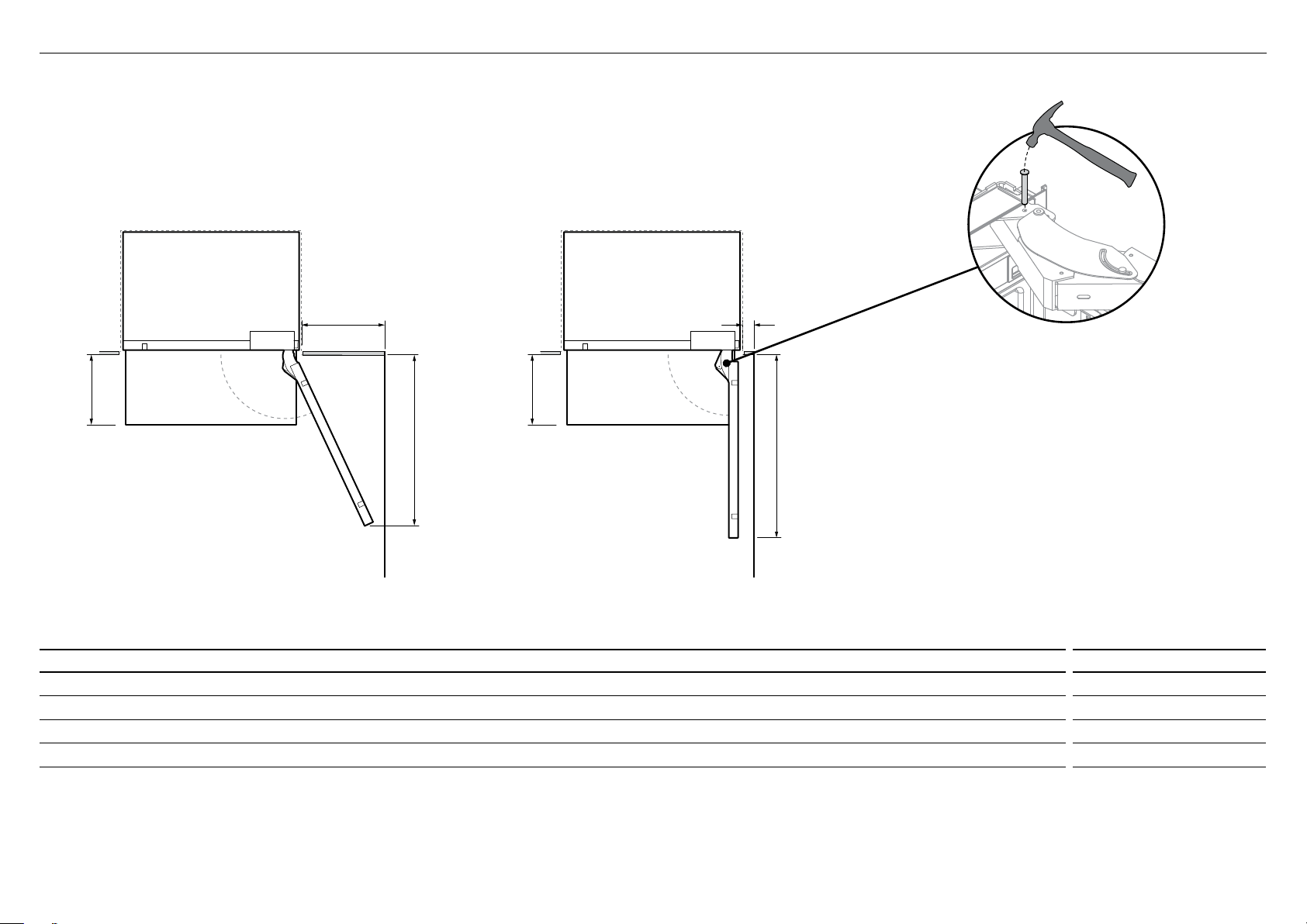
For 90° door swing a hinge limiting pin is supplied with
your appliance. This pin fits in the boreholes of the top
hinge (refer to Z).
WARNING!
A
115° DOOR OPENING
(FULL ROTATION)
Wall Wall
DOOR OPENING AND CLEARANCE DIMENSIONS inches (mm)
Depth of door (widest opening) measured from front of door 37” (940)
A
Depth of drawer (open) measured from front of cabinetry* 14 3/16” (360)
B
Minimum door clearance** to adjacent wall* (115° – full internal access) 16 1/8” (410)
C
Minimum door clearance** to adjacent wall* (90° – reduced internal access) 4 3/8” (110)
D
* Does not include the custom door panels or handles to be manufactured and fitted by cabinetmaker.
** Measured from front cabinetry edge.
90° DOOR OPENING
Before opening doors to the product, ensure the product
is on its base packer and the polystyrene stability blocks
are still in place. Failure to follow these instructions
could lead to serious injury or death.
Drawer must be closed when fitting hinge limiting pin.
Open door to 90°.
1
Using a hammer, drive the hinge limiting pin through the
2
boreholes which are now vertically aligned.
9
Page 12
H
C
A
D
L G
PLAN VIEW
C
B
F
PRODUCT & CAVITY DIMENSIONS
A
PRODUCT & CAVITY DIMENSIONS
B
PRODUCT & CAVITY DIMENSIONS
5 PRODUCT AND CAVITY DIMENSIONS – WITH RD3680 OR RD3680C DOOR PANEL SET
F
F
L G
K
A
J
E
B
I
H
C
FRONT VIEW PROFILE VIEW
CAVITY DIMENSIONS inches (mm)
Overall height of cavity 80” (2032)
A
Overall width of cavity 36” (914)
B
Overall depth of cavity 24 3/4” (629)
C
Total front panel width with required gaps at sides = 36” (914mm) ( E product width + 2 x F cabinetry gaps).
Height of front panels with required gap above = 80” (2032mm) (
D product height + F cabinetry gap).
B
C
5/32” (4mm)
F
PRODUCT DIMENSIONS
Overall height of product* 79 7/8” (2028)
D
Overall width of product 35 11/16” (906)
E
Minimum cabinetry gap clearance from edge of product 5/32” (4)
F
Overall depth of product (excl. front door panels) 23 3/4” (603)
G
Depth of stainless steel toe kick (measured from front of door panels) 4 3/4” (120)
H
Height of stainless steel toe kick** 4” (102)
I
Height of bottom drawer panel 30 3/8” (772)
J
Height of top door panel 45 5/16” (1150)
K
Depth of product front panels (excludes handles)*** 3/4” (19)
L
* Includes mounted feet.
** Alternatively customers can supply their own toe kick, height 4–6” (102–152mm).
*** Optional Fisher & Paykel EZKleen stainless steel or DCS stainless steel front panels - Model no. RD3680(R/L) or
RD3680(R/L)C (non-Water dispensing model) and model no. RD3680RU or RD3680RUC (Ice & Water model).
PLAN VIEW
Flush with front
of cabinetry
inches (mm)
RS36W80RJ or RS36W80RJC models shown with RD3680 or RD3680RC door panels.
10
Page 13

H
C
A
A
L G
PLAN VIEW
C
B
F
PRODUCT & CAVITY DIMENSIONS
A
PLAN VIEW
C
B
F
PRODUCT & CAVITY DIMENSIONS
B
PRODUCT & CAVITY DIMENSIONS
5 PRODUCT AND CAVITY DIMENSIONS – WITH RD3684 AND RD3684C DOOR PANEL SET
F
F
K
L G
D
J
E
I
B
CAVITY DIMENSIONS inches (mm)
Overall height of cavity 84” (2134)
A
Overall width of cavity 36” (914)
B
Overall depth of cavity 24 3/4” (629)
C
Total front panel width with required gaps at sides = 36” (914mm) ( E product width + 2 x F cabinetry gaps).
Height of front panels with required gap above = 84” (2134mm) (
D product height + F cabinetry gap).
H
C
PROFILE VIEWFRONT VIEW
5/32” (4mm)
PLAN VIEW
PRODUCT DIMENSIONS
Overall height of product* 83 7/8” (2130)
D
Overall width of product 35 11/16” (906)
E
Minimum cabinetry gap clearance from edge of product 5/32” (4)
F
Overall depth of product (excl. front door panels) 23 3/4” (603)
G
Depth of stainless steel toe kick (measured from front of door panels) 4 3/4” (120)
H
Height of stainless steel toe kick** 4” (102)
I
Height of bottom drawer panel 30 3/8” (772)
J
Height of top door panel 49 5/16” (1252)
K
Depth of product front panels (excludes handles)*** 3/4” (19)
L
* Includes mounted feet.
** Alternatively customers can supply their own toe kick, height 4 – 6” (102 – 152mm).
*** Optional Fisher & Paykel EZKleen stainless steel or DCS stainless steel front panels - Model no. RD3684(R/L) or
RD3684(R/L)C (non-Water dispensing model) and model no. RD3684RU or RD3684RUC (Ice & Water model).
Flush with front
of cabinetry
inches (mm)
RS36W80RJ or RS36W80RJC models shown with RD3684R or RD3684RC door panels.
11
Page 14

5 PRODUCT AND CAVITY DIMENSIONS – WITH RD3680/RD3684 DOOR PANEL SET
DOOR OPENING & CLEARANCE DIMENSIONS
b
c
a
e
d
b
c
A
115° DOOR OPENING
(FULL ROTATION)
Wall
b
c
90° DOOR OPENING
Wall
e
a
Z
For 90° door swing a hinge limiting pin is supplied with
your appliance. This pin fits in the boreholes of the top
hinge (refer to Z).
WARNING!
Before opening doors to the product, ensure the product
is on its base packer and the polystyrene stability blocks
are still in place. Failure to follow these instructions
could lead to serious injury or death.
Drawer must be closed when fitting hinge limiting pin.
Open door to 90°.
1
Using a hammer, drive the hinge limiting pin through the
2
boreholes which are now vertically aligned.
DOOR OPENING AND CLEARANCE DIMENSIONS inches (mm) inches (mm)
Depth of door (widest opening) measured from front of door 37” (940) 37” (940)
A
Depth of drawer (open) measured from front of drawer, including handle 16 1/2” (420) 15 3/4” (400)
B
Depth of drawer (open) measured from front of drawer, excluding handle 14 3/16” (360) 14 3/16” (360)
C
Minimum door clearance to adjacent wall* (115° – full internal access) 16 15/16” (430) 16 1/8” (410)
D
Minimum door clearance to adjacent wall* (90° – reduced internal access) 5 1/8” (130) 4 3/8” (110)
E
* Measured from front cabinetry edge.
12
12
RS36W80RUC
RS36W80(R/L)JC
RS36W80RU
RS36W80(R/L)J
Page 15

6 CAVITY PREPARATIONS
A
C
Electrical
Plumbing
Alternative area above cavity
for electrical connections
Left side of cavity
29 3/4” (756mm)
5 5/8” (143mm)
Floor
2” (51mm)
Electrical and water connections must be within
this space if located behind the refrigerator
REAR OF CAVITY
2 7/8” (73mm)
IMPORTANT!
For ease of installation, ensure cavity width is consistent top to bottom and height is
consistent left to right.
Electrical
Plumbing
B
3 1/2”
(89mm)
Framed: Finished return
top and sides
For integrated installation, ensure dimensions of finished return dimensions are as shown.
CAVITY DIMENSIONS inches (mm)
Overall height of cavity 80/84” (2032/2134)
A
Overall width of cavity 36” (914)
B
Overall depth of cavity 24 3/4” (629)
C
ELECTRICAL SPECIFICATIONS
Supply 115VAC, 60Hz
Service 10 amp circuit
PLUMBING SPECIFICATIONS
Supply 1/4” (6mm) comp. stainless steel braided hose
Pressure min 22psi (150kPa)
max 120psi (827kPa) @ 68°F (20°C)
Note: electrical connection can be located in an adjacent cabinet to either side of the fridge or above the fridge cavity.
13
Page 16

CUSTOM PANEL DIMENSIONS
Note: Top trim supplied for
84" installation
f
D
A
B
c
e
A
d
e
g
c
Note: top trim supplied for
84” (2134mm) installation
7 CUSTOM DOOR PANEL DIMENSIONS
ISO VIEW
RS36W80RJ or RS36W80RJC models shown only.
When designing custom door panels, these are only available for non-Water
dispensing models.
14
A
e
c
d
CUSTOM PANEL DIMENSIONS inches (mm)
Height of top door panel 45 5/16–49 5/16” (1150–1252)
A
Width of top door and bottom drawer panel 35 11/16” (906)
B
Height of bottom drawer panel* 28 3/8 – 30 3/8” (722 – 772)
C
Height from bottom of product to top of bottom drawerpanel 34 3/8” (874)
D
Gap between top door panel and bottom drawer panel 5/32” (4)
E
Height of toe kick panel* 4 – 6” (102 – 152)
F
Depth of custom panels min. 5/8, max. 3/4” (min. 16, max. 19)
G
Maximum weight of top door panel** 44 lbs (20kg)
Maximum weight of bottom drawer panel** 24 1/4 lbs (11kg)
Custom door panels to be manufactured and fitted by cabinetmaker.
Door handle kit is available as an optional accessory.
* Stainless steel toe kick, height 4” (102mm) is supplied with the appliance. For integrated installation, a custom toe kick 4 – 6”
(102–152mm) can be manufactured and fitted by cabinetmaker. The bottom grille can be reduced to allow for a higher toe kick.
Adjust the height of the bottom drawer panel accordingly.
** Includes weight of handle.
PROFILE VIEW
RS36W80J
RS36W80JC
Page 17

7 CUSTOM DOOR PANEL DIMENSIONS
The drawings below apply to non-Water dispensing models only (RS36W80(R/L)J/RS36W80(R/L)JC). Dimensions apply for the preparation and installation of custom door panels.
For Dwg and Dxf files of the below panel preparation download the folder on http://thekitchentools.fisherpaykel.com or http://www.dcsappliances.com/designers-architects/
301/16”
22”
1311/16”
59/16”
Ø 3/32” REF
12x Pilot holes recommended for bracket attachment.
(Do not penetrate front surface).
Ensure handle is mounted
29/16” from edge of panel
to the center – this will avoid
interference with brackets.
2415/16”
2615/16”
385/8”
40”
153/16”
51/16”
Ø 3/32” REF
10x Pilot holes recommended for
bracket attachment.
(Do not penetrate front surface).
All measurements
to be made from
bottom left corner.
17/16”
341/4”
TOP PANEL – REAR VIEW
415/16”
615/16”
215/16”
11/8”37/16”
All measurements to be made
from top and centerline.
193/8”
163/8”
Cutouts are located in attachment bracket for Fisher & Paykel and DCS handles only.
If locating custom handle in the shaded area shown above, ensure handle screw heads
are countersunk into back of panel to avoid interference with hanging bracket.
BOTTOM PANEL – REAR VIEW
15
Page 18

8 80” (2032mm) CAVITY – ATTACH ANTI-TIP BRACKET
IMPORTANT!
Safety requires refrigerators be stable when door and/or drawer, are open. The anti-tip bracket and fittings supplied must be fitted to the wall of the finished enclosure to withstand
a220.5lb (100kg) load. This will prevent the possibility of the appliance tipping forward, when door and/or drawer, are open.
WARNING!
Failure to follow instructions can lead to serious injury or death.
When fastening with masonry plugs and/or screws:
Ensure the screws avoid electrical, gas and water conduits.
Ensure the surface the bracket is fastened to withstands a 220.5lb (100kg) load.
Ensure light-weight masonry material such as cinder block and new concrete (no curing time) are not used in installation.
Do not use metallic materials that may corrode, stain and/or damage the enclosure.
For 80” (2032mm) cavity installation
Wooden/plaster board wall installation
Project the end of the above finished enclosure to the center of the back wall and
1
subtract 27/16” (62mm). This will locate the contact surface between the bracket and
the appliance (refer toA).
Ensure a structural beam/wall stud closest to the center of the wall enclosure is located.
Fix bracket to the wall with screws x4 (#10 x 40 pan head Phillips screws).
2
Ensure screws hold tight and the bracket overlaps the appliance when it is positioned
(23/8” min. (60mm)) for a secure hold.
Solid wall installation
Project the end of the above finished enclosure to the center of the back wall and
1
subtract 27/16” (62mm). This will locate the contact surface between the bracket
and the appliance (refer toB).
Mark screw locations to drill Ø1/4” x 13/8” (Ø6mmx35mm) deep holes. Hammer
2
masonry plugs into the wall until flush x4. Fix bracket to the wall with screws x4
(#10 x 40pan head Phillips screws). Ensure screws hold tight.
Spacer installation
If a minimum 23/8” (60mm) overlap cannot be achieved we recommend
fastening a solid spacer (wooden beam etc) behind the bracket.
Ensure the length of the spacer corresponds to the enclosure’s width. Always
1
secure the spacer to existing studs on the enclosure wall (refer toC).
Fix bracket to the spacer with screws x4 (#10 x 40 pan head Phillips screws).
2
Ensure screws hold tight and the bracket overlaps the appliance when it is
positioned (23/8” min. (60mm)) for a secure hold.
16
Subtract 27/16” (62mm) from
above finished enclosure
23/8” min.
(60mm)
overlap
PROFILE VIEW
Subtract 2 7/16” (62mm) from
above finished enclosure
23/8” min.
(60mm)
overlap
PROFILE VIEW
Subtract 27/16” (62mm) from
above finished enclosure
23/8” min.
(60mm)
overlap
PROFILE VIEW
A
Bracket
B
Bracket
C
Spacer
Bracket
Page 19

8 84” (2134mm) CAVITY – ATTACH ANTI-TIP BRACKET
IMPORTANT!
Safety requires refrigerators be stable when door and/or drawer, are open. The anti-tip bracket and fittings supplied must be fitted to the wall of the finished enclosure to withstand
a220.5lb (100kg) load. This will prevent the possibility of the appliance tipping forward, when door and/or drawer, are open.
WARNING!
Failure to follow instructions can lead to serious injury or death.
When fastening with masonry plugs and/or screws:
Ensure the screws avoid electrical, gas and water conduits.
Ensure the surface the bracket is fastened to withstands a 220.5lb (100kg) load.
Ensure light-weight masonry material such as cinder block and new concrete (no curing time) are not used in installation.
Do not use metallic materials that may corrode, stain and/or damage the enclosure
For 84” (2134mm) cavity installation
Wooden/plaster board wall installation
Project the end of the above finished enclosure to the center of the back wall and
1
subtract 61/2” (164mm). This will locate the contact surface between the bracket and
the appliance (refer toA).
Ensure a structural beam/wall stud closest to the center of the wall enclosure is located.
Fix bracket to the wall with screws x4 (#10 x 40 pan head Phillips screws).
2
Ensure screws hold tight and the bracket overlaps the appliance when it is positioned
(23/8” min. (60mm)) for a secure hold.
Solid wall installation
Project the end of the above finished enclosure to the center of the back wall and
1
subtract 61/2” (164mm). This will locate the contact surface between the bracket
and the appliance (refer toB).
Mark screw locations to drill Ø1/4” x 13/8” (Ø 6mm x 35mm) deep holes. Hammer
2
masonry plugs into the wall until flush x4. Fix bracket to the wall with screws x4
(#10 x 40 pan head Phillips screws). Ensure screws hold tight.
Spacer installation
If a minimum 23/8” (60mm) overlap cannot be achieved we recommend
fastening a solid spacer (wooden beam etc) behind the bracket.
Ensure the length of the spacer corresponds to the enclosure’s width. Always
1
secure the spacer to existing studs on the enclosure wall (refer toC).
Fix bracket to the spacer with screws x4 (#10 x 40 pan head Phillips screws).
2
Ensure screws hold tight and the bracket overlaps the appliance when it is
positioned (23/8”min. (60mm)) for a secure hold.
Subtract 61/2” (164mm) from above
finished enclosure
23/8” min.
(60mm)
overlap
PROFILE VIEW
Subtract 61/2” (164mm) from above
finished enclosure
23/8” min.
(60mm)
overlap
PROFILE VIEW
Subtract 61/2” (164mm) from above
finished enclosure
23/8” min.
(60mm)
overlap
PROFILE VIEW
A
Bracket
B
Bracket
C
Spacer
Bracket
17
Page 20

8 84” (2134mm) CAVITY – ATTACH TOP TRIM
WARNING!
Take care when working with the appliance outside of the finished enclosure, as the
appliance is not secured and has the possibility of tipping forward. Tipping of appliance
can lead to serious injury or death.
Ensure all external packaging material is removed from the appliance before installation.
1
~
13” (330mm)
~
13” (330mm)
A
On the right side of the top trim, insert M5 nuts x2 onto the top and bottom slide.
2
Slide nuts towards the center of the trim, ~ 13” (330mm).
Repeat this process on the opposite side.
~
13” (330mm)
~
13” (330mm)
Position joining brackets over the M5 nuts. Thread screws x2 (M5 x 8 pan head Phillips
3
screws) through bracket hole and secure.
Repeat this process on the opposite side.
18
At the top of the appliance, place the assembled top trim behind the existing appliance
4
trim. Bring the top trim forward and insert screw heads through the key holes of the joining
brackets (refer toA).
B
Slide the screws located on the appliance sideways towards the narrow side of the key holes
5
on the joining bracket, and tighten screws to lock top trim in position (refer toB).
Page 21

9 ATTACH SIDE BASE BRACKETS AND DOOR STUDS
WARNING!
Take care when working with the appliance outside of the finished enclosure, as the
appliance is not secured and has the possibility of tipping forward. Tipping of appliance
can lead to serious injury or death.
Ensure all external packaging material is removed from the appliance before installation.
1
At the base LH side of the appliance attach the LH side bracket to the dedicated
2
threaded holes and secure with screws x2 (M5 x 8 countersunk Phillips screws).
Repeat this process on the RH side of the appliance.
LH orientation
Secure M8 studs into the refrigerator
3
doors, ensure the open end faces the top
and the studs go all the way in.
Repeat this process for all
refrigeratordoors.
Loosely screw (1–2 turns) M5 x 10 pan
4
head Phillips screws into doors.
Repeat this process for all
refrigeratordoors.
1 – 2 turns
19
Page 22

!0 CONNECT TO WATER AND ELECTRICAL SUPPLY
IMPORTANT!
The water connection instructions below are intended only for the professional installer.
DO NOT use with water that is microbiologically unsafe or of unknown quality.
WARNING – connect to potable drinkable water supply only.
DO NOT install on line pressure above 120psi (827kPa) or below 22psi (150kPa).
DO NOT use on hot water supply (100°F [38°C max.]).
AVOID contamination of pipes during installation.
Old water fittings (hose-sets) should not be reused.
The standard appliance includes a stainless braided water line hose. 1/4 ” copper tubing is compatible with the system, it needs to be purchased separately and must comply with local
regulations.
The shut off valve should be accessible.
Ensure the refrigerator is NOT plugged into a power supply. Locate isolating faucet for
1
water connection – cold water supply only. Tee and faucet fittings are not supplied.
Position the appliance 1.5–2ft. (450–600mm) in front of the finished enclosure. This
will allow access behind the appliance for power and water connections.
1.5–2ft.
(450–600mm)
Firmly insert the tube end of the adaptor into the PLV, until the end is no longer visible.
3
Once inserted, pull gently on tubing to ensure it is locked in (refer to A).
Note: dislodge the PLV if required.
PLV
A
B
At the front of the appliance, fasten
2
the adaptor onto one end of the
braided water line hose.
Note: the adaptor is not required for
installation, if 1/4”PEX plastic tubing
isused.
20
Secure connection by attaching the locking key in between the PLV and tube end of the
4
adaptor (refer to B).
Note: if PLV was dislodged for installation (3), mount PLV back into clip.
Page 23

!0 CONNECT TO WATER AND ELECTRICAL SUPPLY
Thread the free end of the water line hose into the dedicated hole located in the base of the
5
appliance, through to the back of the appliance (refer to C).
At the back of your appliance, connect the appliance to the electrical supply (115VAC, 60Hz)
7
with the fitted plug and lead, and turn on. Ensure the appliance is connected to its own
isolating switch (refer toE).
23/8” min.
(60mm)
overlap
I
D
C
At the back of the appliance, loosely coil the water line hose (
6
end of the hose to the cold water supply (refer to D).
Take care not to over-tighten the connection. Turn the isolating faucet on and check that
all connections are dry and free of drips.
2 – 3 times) and fasten the
~
E
G
Final location
F
In order to push appliance into correct position:
8
Stop midway, reach through base to locate power cord. Pull power cord through the front left
side of the appliance (refer to F), tucking it neatly in the left side of the base (refer to G).
Reach through base to locate water line hose coil. Tuck coil neatly into front right side of
base (refer to H).
of power cord,
left side of base
Final location
of water tube,
right side of base
IMPORTANT!
Failure to do this can result in running over the hose causing damage and possible
waterleaks.
Push product until doors are in line with the frame. Ensure the appliance is centered.
Firm contact must be achieved between the appliance and the anti-tip bracket,
23/8”min.(60mm) overlap (refer to I ).
H
WARNING!
Failure to follow this instruction can lead to serious injury or death.
21
Page 24

!1 PRE-ALIGN YOUR PRODUCT INSIDE CABINETRY
IMPORTANT!
It is important that the doors are in line with the frame and the appliance is centered before following these steps.
It is important that all four corners of the appliance are supported firmly onto the floor to eliminate any movement.
Installing the appliance on a soft, uneven, or not level floor may result in twisting of the product and poor door sealing.
Raise the appliance using an 7/16” (11mm) hex socket or 3/16” (4mm) hex Allen key. One turn of height adjusting nuts is equivalent to 1/16” (1mm) height travel.
Note: maximum travel is 13/16” (20mm).
Use low torque setting to avoid damage to height adjustment system.
Use the front and rear adjustment nuts (A) to align the front of the doors top to bottom on both
1
sides. Depending on your installation design the refrigerator door may be flush with the cabinet
frame or the cabinet door. Place a ruler on the front of the product to check flushness top and
bottom, left and right. This step will help ensure the refrigerator is level with the adjacent cabinetry.
IMPORTANT!
Failure to achieve flushness top to bottom and/or uneven gaps left to right greater than 1/16”
(1.5mm) can lead to difficulties achieving final alignment. Final alignment will be achieved once
door panels have been installed and the appliance is pushed back to sit flush with cabinetry.
Turn adjustment nuts clockwise to raise or counter-clockwise to lower (refer to A).
Check gaps between appliance and adjacent cabinetry are even on both sides (refer to B).
Gently push the front of the product to check the stability.
Place a ruler on the front of
the product to check flushness
top and bottom, left and right.
B
22
A A
Front roller adjustment
Rear roller adjustment
Page 25

!2 INSTALL WATER FILTER CARTRIDGE AND KICKSTRIPS
IMPORTANT!
The water filter head must be firmly pushed into the product and secured, incorrect installation can lead to water leaks.
It is not necessary to shut off the water supply when installing the water filter.
Remove the red protective cap on the spigot head and align the filter cartridge tool over the
1
filter handle
Front view
Pull the freezer drawer out slightly and insert the filter cartridge and tool into the bottom
2
left of the product. Firmly push the cartridge in until the filter head cannot be pushed
anyfurther.
A
Installing kickstrip filter
4
Remove filter from inside the product. Fit the filter onto the rails and push to the rear until it
clips securely (refer to A).
C
B
Filter cartridge in the locked position.
Turn 90° clockwise to tighten. Remove filter cartridge tool and close freezer drawer.
3
Top kickstrip grille
5
Ensure the top grille is inserted in the correct orientation (refer to B). Align the top grille
clips to the top plinth slots then firmly push grille onto appliance until the clips engage
(refer to C).
23
Page 26

!3 ASSEMBLE DOOR PANEL SET
The assembly of Fisher & Paykel (EZKleen stainless steel) and DCS (Stainless steel) door panels and custom door panels are outlined below. To protect the finish of the Fisher & Paykel EZKleen
stainless steel and DCS stainless steel door panels, leave protective film on the panels when hanging and remove film only when installation is complete.
If using custom door panels ensure they are prepared as per ‘Custom door panel dimensions’ section.
Door panel
Mounting handle (refer to A)
1
For Fisher & Paykel door panel sets or DCS door
panel sets, remove the plastic plugs from the
handle holes x4. Align the handle to the holes
and secure with screw handle x4 (M5 x 25 pan
head socket screws).
For custom panels, ensure handle is secured
29/16” (65mm) from the inner edge of the
panel to the center – this will avoid interference
with bracket installation.
Hanging bracket (refer to B)
2
For Fisher & Paykel door panel sets or DCS door
panel sets, align the bracket to the holes and
secure with screws x6 (M5 x 14 Mush Phillips SS).
For custom panels, secure bracket with screws
x6 (#8 x 16 Mush washer screws).
Side brackets and straps (refer to C)
3
For Fisher & Paykel door panel sets or DCS
door panel sets, align bracket and strap to the
holes on the side of the panel and secure with
screws x2 (M5 x 14 Mush Phillips SS).
Drawer door panel
Mounting handle (refer to D)
4
For Fisher & Paykel door panel sets or DCS
door panel sets, remove the plastic plugs from
B
A
the handle holes x4. Align the handle to the
holes and secure with screw handle x4 (M5 x
25 pan head socket screws).
For custom panels, ensure handle screw heads
are counter sunk into the back of the panel to
avoid interference with hanging bracket.
Hanging bracket (refer to E)
5
For Fisher & Paykel door panel sets or DCS
door panel sets, align the bracket to the holes
and secure with screws x6 (M5 x 14 Mush
Phillips SS).
For custom panels, secure bracket with screws
x6 (#8 x 16 Mush washer screws).
Side brackets and straps (refer to F)
6
For Fisher & Paykel door panel sets or DCS
door panel sets, align bracket and strap to the
holes on the side of the panel and secure with
screws x2 (M5 x 14 Mush Phillips SS).
E
D
For custom panels, secure bracket with
screws x2 (#8 x 16 Mush
washer screws).
Repeat this
process for all
brackets and
straps.
24
For custom panels, secure bracket with screws
x2 (#8 x 16 Mush washer screws).
Repeat this process for all brackets and
straps.
C
F
Page 27

!4 HANG ICE & WATER DOOR PANEL
For Fisher & Paykel EZKleen stainless steel and DCS stainless steel door panels only.
Remove the external display
1
module from inside the product.
Thread the display harness
through the door panel cavity.
Ensure the grommet is engaged.
Angle top display tabs into the
2
door panel. Ensure the harness
is free of pinching. Firmly push
against bottom display tabs
and insert into the door panel
until you feel it clip securely.
Ensure the display is flush with
the door panel.
Connect display harness
5
onto the refrigerator door
by inserting firmly until
you feel it clip securely
(refer to B).
On the external display,
enable the dispenser lock,
this will help prevent any water
from dispensing during water
connection. To lock, press the button
for 4 seconds. The LED above the button
will illuminate.
B
A
Remove water tube from holder
3
on the refrigerator door.
Hang door panel onto M8 studs.
4
Ensure the panel is free to pivot
for water connections (refer to A).
Firmly push the water
6
tube into the spigot
behind the door panel
until the marked line is not
visible.
Ensure the water tube is routed away from
any sharp objects, sharp corners, and not
in a location where it can be kinked or
squashed when the door panel is secured,
(as this will stop water flow).
Flush water filtration system. See page 27.
To secure door panel, follow the instructions
in the next section: ‘Hang non-Water
dispensing door panels’.
25
Page 28

!5 HANG NON-WATER DISPENSING DOOR PANELS
For Fisher & Paykel EZKleen stainless steel and DCS stainless steel door panels and custom panels.
IMPORTANT!
Remove protective film from white product
doors before hanging door panels.
Hang all door panels onto M8 studs and align
1
the side bracket forks onto the refrigerator door.
– Ensure the forks are positioned around the
body of the side screws (M5 x 10 pan head
Phillips screw).
Push the product until the door panels are flush.
2
Depending on your installation design this will
be flush with your adjacent cabinetry or your
framework. Place a ruler on the front of the
product to check flushness top and bottom, left
and right (refer to drawing below).
Ensure the gap between the top of the door
3
panel and the top cabinetry is no greater
than 1/4” (7mm). To reduce this gap, raise the
product by turning all four adjustment nuts the
same number of turns.
IMPORTANT!
Failure to follow these steps can lead to
difficulties in door panel adjustment and
cosmetic cap fitment.
All door panels have full axis adjustment to ensure
5
they are flush with adjacent walls. To adjust the
height of each panel turn clockwise to raise stud or
counter-clockwise to lower stud (refer to A).
A
B
Once satisfied with all door panels, secure M8 studs
6
with M8 washer and M8 nut (refer to B). The top of the
stud must remain below the top face of the door panel.
C
Lock top panel side screw to allow
4
opening the door without affecting
adjustment.
26
Place a ruler on the front of
the product to check flushness
top and bottom, left and right.
D
Secure side bracket forks by tightening side screws (C).
7
Repeat this process for all door panels.
Note: for depth adjustment loosen side screws x4,
adjustpanels and then retighten oncesatisfied.
Note: further adjustment of door panels can be achieved by removing door panels
then loosening the fixing screws for the hanging bracket and moving the bracket
sideways to suit.
Loosely install locking bracket into the pocket on the underside of the door using a
8
M8 stud (D). Slide the locking bracket out until it touches the back of the door panel.
Screw in place using a #8 x 16 screw through one of the three slotted holes. Fully
tighten the M8 stud.
Page 29

!6 ICE AND WATER INITIATION
Now it is time to carry out the ice and water initiation to ensure you are free of leaks before fully installing the product. Ensure the appliance is switched on and the isolation faucet has been
connected and turnedon.
Ice maker initiation
To initiate ice maker before use:
When the appliance is first turned on after installation, the ice maker will be off.
To activate the automatic ice maker, press the ‘Ice On/Off’ button once. The LED light
above the button will illuminate indicating the ice maker is on.
Press and hold the , and together for 4seconds then close the doors. The ice tray
will flip twice and empty the water into the bin below. The ice tray will flip only after the
doors are closed.
Force another cycle, this step helps remove any manufacturing and transportation dust in
the ice tray.
Empty the water and correctly replace the bin, ensuring the scoop is located at the front of
the bin.
Once the ice maker is in operation, discard the first 24hours of ice. This will flush away any
impurities in the water line.
For more information on making ice please refer to the User Guide supplied with
thisappliance.
Water dispenser initiation (Ice & Water models only)
To flush the water filtration system before use:
Press the water dispenser pad until water dispenses, this will
displace trapped air in the water tank and filter system. This
will take at least 2 minutes. Once the water has dispensed,
rest the dispenser for 2 minutes.
Dispense and discard 4qt (4L) of water, then rest the
dispenser pad for a further 2 minutes.
Dispense and discard a further 4qt (4L) of water. Failure to
do this will result in excessive dripping from the dispenser.
Once installation is complete, a few drips may appear out of
the dispenser over the next few days to clear the remaining
trapped air.
Ensure the refrigerator has cooled for at least 2hours
beforeuse.
Water dispenser
IMPORTANT!
Do not continually dispense water for longer than 2minutes at a time.
For more information on water dispensing please refer to the User Guide supplied with
thisappliance.
27
Page 30

!7 ATTACH FIXING BRACKETS
Carefully open the refrigerator door
1
to attach fixing brackets. Place fixing
bracket over the side of the appliance and
secure mid-way with screws x2 (M5 x 8
countersunk Phillips screws).
Secure the center of each fixing bracket to the
2
side of the adjacent wall with screws x2 (#8 x 19
twin thread screws).
Repeat this process for the remaining brackets.
Slide screw cover in between the fixing
3
bracket and the side bracket on the
appliance x1.
Repeat this process for the remaining
screw covers.
Fix screw cover by tightening screws x2
4
(M5x8 countersunk Phillips screws).
Repeat this process for the remaining screw.
28
Page 31

!8 ATTACH COVERS AND TOE KICK
The standard appliance includes a stainless steel toe kick (4” (102mm)) and the hardware required to mount the toe kick (4” (102mm)). Alternatively the customer can supply their own toe kick
(4– 6” (102 – 152mm)) for complete integration of the appliance.
If applicable, remove any remaining
1
protective film on your door panels.
A
B
Open the refrigerator door, firmly push top
2
cover over the top studs.
Repeat this process for the freezer drawer.
Open the refrigerator door, firmly push side
3
cover over the side studs.
Repeat this process for the freezer drawer.
Installing toe kick
4
Unscrew the toe kick bracket screws mid-way, and bring forward (refer to A and B).
Repeat this process on the opposite side.
C
Place toe kick in front of the brackets and gently push towards the appliance until flush with
5
surrounding cabinetry. Once satisfied, remove the toe kick.
Tighten the toe kick bracket screws to lock brackets into position and remove the backing
6
from the Velcro strip (refer toC). Attach toe kick to the adhesive surface.
29
Page 32

!9 ATTACH BOTTOM GRILLES
SCALE 1 : 1
IF TOEKICK IS HIGHER THAN 4" USE SIDE CUTTER TO
1.
CUT UNREQUIRED VANES FROM DOTTOM
DRILL HOLES THROUGH DIMPLES
2.
USE PROVIDED SCREWS TO FIX GRILL TO
3.
MATCHING HOLES ON PLASTIC PARTS
DETAIL A
SCALE 1 : 1
DETAIL A
SCALE 1 : 1
SCALE 1 : 1
IF TOEKICK IS HIGHER THAN 4" USE SIDE CUTTER TO
1.
CUT UNREQUIRED VANES FROM DOTTOM
DRILL HOLES THROUGH DIMPLES
2.
USE PROVIDED SCREWS TO FIX GRILL TO
3.
MATCHING HOLES ON PLASTIC PARTS
DETAIL A
SCALE 1 : 1
DETAIL A
SCALE 1 : 1
DETAIL A
SCALE 1 : 1
For custom toe tick greater than 4” (102mm)
Measure the required height for the bottom grille. On a board, carefully score/cut
1
theun-required vanes from the bottom of the kickstrip grille and discard (refer to A).
Drill Ø5/32” (4mm) holes into the dimples of the grille (refer toB).
2
Repeat this process for all dimples.
Cut un-required vanes from the bottom of the grille
Grille tabs
B
C
Front right view
A
For toe kick installation at 4” (102mm)
With the grille tabs facing upwards, align the grille clips to the bottom of the plinth’s slots,
1
then firmly push grille onto the plinth (refer to A).
A
Grille tabs
Align the air flow divider underneath the grille tabs indicator and clip onto the vanes of the
2
bottom grille (refer to B).
With the grille tabs facing upwards, align the grille to the bottom of the plinth where the
3
screw holes are located and secure with screws x3 (#8 x 5/8” pan head screws) (refer to C).
Align the air flow divider underneath the grille tabs indicator and clip onto the vanes of the
4
bottom grille (refer to D).
D
30
B
Page 33

TWO METHODS ARE AVAILABLE FOR ATTACHING SIDE TRIM BRACKETS:
0
(A) FLEXIBLE SPRING CLIP METHOD – RECOMMENDED METHOD
(B) FIXED SCREW METHOD – METHOD TO USE IF CABINET IS NOT TO SPECIFICATION
(Attempt method A. If method A results in poor fitment of side trims due to cabinetry that is uneven or out of specification, use method B).
@0 ATTACH SIDE TRIM BRACKETS – (A) FLEXIBLE SPRING CLIP METHOD
IMPORTANT!
Before installing your appliance, ensure the dimensions of the finished enclosure are correct for your appliance following the‘Product and cavity dimensions’ sections.
Break off the datum lip to each side
1
trim bracket and discard.
Repeat for all side trim brackets.
For 80” (2032 mm) cavity installation only
Measure 4” (102mm) from the top, shorter side trim
2
and carefully cut using a fine tooth hacksaw to a
length of 76“ (1930mm). Referto A for orientation
of side trim.
Note: ensure cut is straight and square as this is an
exposed surface. Also ensure the plastic part does
not bend as this can causevisual stress marks.
Repeat this process for the remaining sidetrim.
Discard
Position 3 side trim brackets onto each side trim.
3
Note: measure from the top of the trim, with the
shorter lip at the bottom. (Refer to B for 80” and
84” bracket locations and trim orientation).
80” = 9” (229mm)
84” = 13” (330mm)
IMPORTANT!
Each bracket has two engagement points for the
side trim to locate. Ensure the trim is engaged in
both points (refer to C).
Repeat this process for the remaining side trim.
A
PlasticAluminum
Side trim
bracket
Side trim
Top view of side trim engaged
correctly in side trim bracket
C
80” = 36” (914mm)
84” = 40” (1016mm)
80” = 65” (1651mm)
84” = 69” (1753mm)
B
31
Page 34

@0 ATTACH SIDE TRIM BRACKETS – (A) FLEXIBLE SPRING CLIP METHOD
Spring clip
G
Side trim lip
F
D
Top view of spring clip correctly inserted
between side trim and side trim bracket
Insert the spring clip into the gap between the side trim and side trim bracket,
4
orientation as shown in figures D and E.
E
IMPORTANT!
Ensure spring clip is correctly oriented with the open loop facing the side trim lip.
Repeat this process for the remaining side trim.
32
Open refrigerator door. Place the assembled side trim with brackets and spring clips against
5
the alcove side wall with the shorter lip facing the bottom (refer to F).
IMPORTANT!
Ensure the side trim is positioned as high as it will go.
Push the side trim at each bracket location until there are no visible gaps between the trim
and cabinetry (refer to G).
Repeat this process for the remaining side trim.
Page 35

@0 ATTACH SIDE TRIM BRACKETS – (B) FIXED SCREW METHOD
If method A has resulted in poor fitment of side trims due to cabinet being out of spec, use method B.
IMPORTANT!
Before installing your appliance, ensure the dimensions of the finished enclosure are
correct for your appliance following the‘Product and cavity dimensions’ sections.
Break off the datum lip to each side
1
trim bracket and discard.
Repeat for all side trim brackets.
Discard
69” (1753mm)
~
40” (1016mm)
~
2” (50mm)
2” (50mm)
C
For 80” (2032 mm) cavity installation only
Measure 4” (102mm) from the top, shorter side trim
2
and carefully cut using a fine tooth hacksaw to a
length of 76“ (1930mm). Referto A for orientation
of side trim.
Note: ensure cut is straight and square as this is an
exposed surface. Also ensure the plastic part does
not bend as this can causevisual stress marks.
Repeat this process for the remaining sidetrim.
A
PlasticAluminum
10” (254mm)
~
Front of
cabinet
B
Position three side trim brackets on each side (refer to B for bracket locations). Open the
3
appliance door. Measure 2” (50mm) from the front of refrigerator (from behind the door),
to the front of the alcove and accurately mark a vertical line (refer to C).
Align the bracket edge with the marked line and using screws x2 (#8 x 16 mush washer)
fix the bracket to the cabinetry x3.
Repeat on the opposite side.
IMPORTANT!
Inaccurate positioning of bracket can result in inability to fit side trim or gaps between
side trim and appliance.
33
Page 36

Suggestion by Derek showing
engagement in 2 places
“ensure they are fully engaged”
@0 ATTACH SIDE TRIM BRACKETS – (B) FIXED SCREW METHOD
Place the side trim against the alcove side wall with the shorter lip facing the bottom (refer to D).
4
Ensure the side trim is positioned as high as it will go.
Engage the side trim with the brackets by pushing the trim inwards at the locations of the top and middle side trim brackets. Once the trim has engaged with top and middle brackets, then push
and engage the side trim at the location of the bottom bracket (refer to E).
IMPORTANT!
Ensure there are no visual gaps between the product and side trims.
Each bracket has two engagement points for the trim to locate. Ensure the trim is engaged at both points (refer to F).
Repeat this process for the remaining side trim.
Correct visual gaps by loosening side trim screws and moving trim within clearance. Iffurther adjustment is required, relocate brackets to desired position.
34
Side trim
D
E
Top view of side trim engaged
correctly in side trim bracket
F
Side trim bracket
Page 37

@1 ADJUST HINGE TENSIONING SCREWS
Hinge tensioning screws can be tightened if increased door closing force is required.
To ensure the door shuts on its own, when pushed within the self close activation range, the hinge tensioning screws need to be tightened. The hinge tensioning screw is located in the door
1
hinge. To tighten the screw, rotate the screw to the right (refer to A).
Repeat this process on bottom hinge tensioning screw.
A
Hinge tensioning screw
35
Page 38

@2 FINAL CHECKLIST
TO BE COMPLETED BY THE INSTALLER
All models
Check all parts are installed.
Ensure the appliance is level.
Ensure the appliance is securely fastened to the cabinetry with the supplied
anti-tip bracket and fittings.
Ensure the door/drawer can open and close freely with no resistance from
surrounding cabinetry.
Ensure hinge limiting pin is fitted for 90° door swing.
Ensure all internal and external packaging is removed from the appliance
before use.
Ensure a manual ice maker cycle has been forced.
Ice & Water models only
Ensure the water filtration system has been flushed.
Complete and keep for safe reference:
Model
Serial No.
Purchase Date
Purchaser
Dealer Address
Installer’s Name
Installer’s Signature
Installation Company
Installation Date
36
Page 39

Page 40

www.fisherpaykel.com
www.dcsappliances.com
The product specifications in this booklet apply to the specific products
and models described at the date of issue. Under our policy of continuous
product improvement, these specifications may change at any time. You
should therefore check with your Dealer to ensure this booklet correctly
© Fisher & Paykel Appliances 2016. All rights reserved.
describes the product currently available.
US CA
844189 A 04.16
 Loading...