

DCS RGU486GDN, RGU305L, RGU364GLN, RGU364GDL, RGU484GGL Specification Sheet
...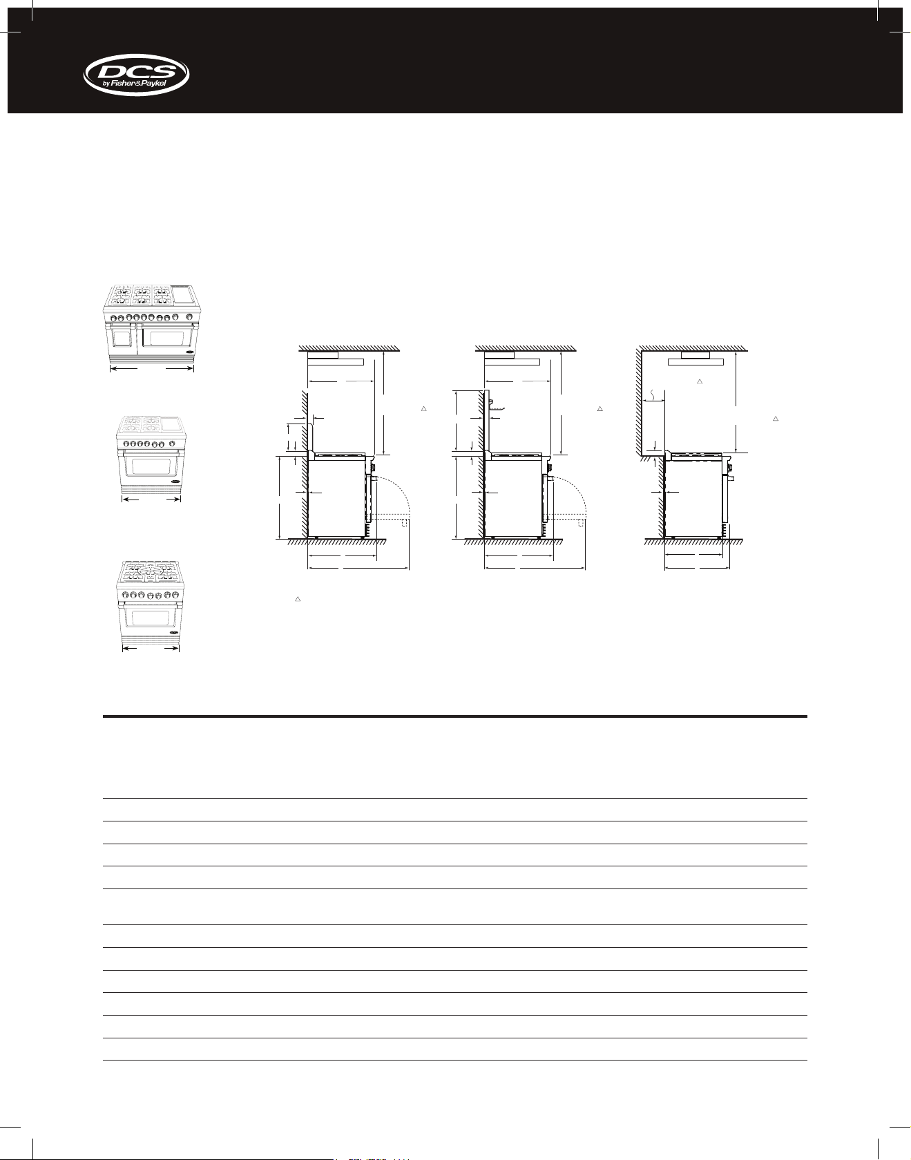
GAS RANGES PRODUCT DIMENSIONS
RGU-48, RGU-36, RGU-30 & RGUC-30
RGU-48
Standard Installation:
using the appropriate range mount
Standard backguard model: BGRU1248, BGRU-1236, or BGRU-1230
Full Backguard Installation:
using the appropriate wall mount Full
backguard model: BGRU-3048,
BGRU-3036, or BGRU-3030
www.dcsappliances.com p. 888-936-7872
Island Installation:
using the integral island trim only
a
RGU-36
a
RGU-30
RGUC-30
a
PRODUCT DIMENSIONS (INCHES)
Hood
H
51” Min. to
I I
combustibles
B
Hood Hood
H
C
D
0” Clearance 0” Clearance
E
D
E
F
G
As defined in the “National Fuel Gas Code” (ANSI Z223.1, latest edition).
The horizontal surfaces of the cooktop trim must not be below countertop level.
G
51” Min. to
combustibles
12” Min. to
combustibles
without backguard
,
51” Min. to
combustibles
D
0” Clearance
F
J
K
Important!
If using the island trim only, a 12” clearance is
required between the back of the range and a
combustible surface (above the cooking surface).
If the clearance is less than 12”, the back wall
must be non-combustible and made of heatresistant material.
RGU-48
7
Width of product 47 –
A
Height of full backguard 26 –
B
Height of standard backguard 8 –
C
Height of integral island trim 3 –
D
Height of product (from floor to cooktop trim, excluding grates
E
and island trim)
Maximum depth from wall to front of product (including handle) 30 –
F
Maximum depth from wall to front of product with door open 46 –
G
Maximum depth from wall to front of product (excl. handle and knobs) 29” 29” 29
H
Depth of Backguard 1 –
I
Depth from wall to front of range side panel 25” 25” 25”
J
Depth of product from wall to oven door front (excl. handle) 27 –
K
Product dimensions and specifications are listed as a guide only. For complete installation instructions and specifications, refer to the product Use & Care Guide/Installation Instructions available at www.dcsappliances.com
6467_USA_DCS_RANGE SPEC SHEETS_FLI.indd 7 31/03/14 10:07 AM
/
1
/
1
/
1
/
min. 35 –
max. 36 –
1
/
11
/
5
/
16
1
/
” 35 –
8
” 26 –
2
” 8 –
2
” 3 –
2
3
/
”
4
3
/
”
4
” 30 –
4
” 46 –
16
” 1 –
” 27 –
2
RGU-36
7
/
1
/
1
/
1
/
min. 35 –
max. 36 –
1
/
11
/
5
/
16
1
/
” 29 –
8
” 26 –
2
” 8 –
2
” 3 –
2
3
/
”
min. 35 –
4
3
/
”
max. 36 –
4
” 30 –
4
” 46 –
16
” 1 –
” 27 –
2
RGU-30
RGUC-30
7
/
1
/
1
/
2
1
/
2
1
/
11
/
5
/
16
1
/
”
8
”
2
”
”
3
/
”
4
3
/
”
4
”
4
”
16
”
”
2
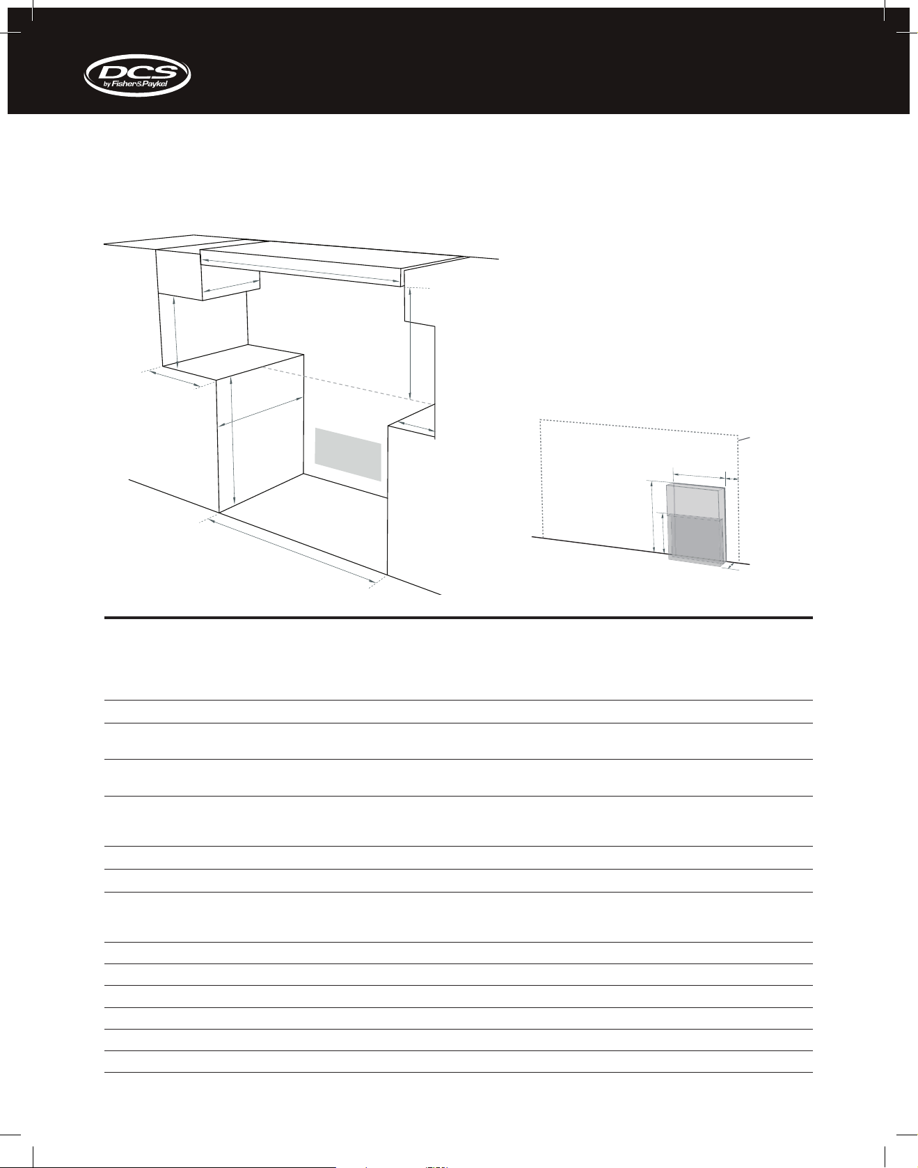
GAS RANGES CABINETRY DIMENSIONS
RGU-48, RGU-36, RGU-30 & RGUC-30
a
E
www.dcsappliances.com p. 888-936-7872
B
Cooking Surface
D
C
LOCATION OF ELECTRICAL AND GAS SUPPLY
H
see diagrams
following for
G
electrical and gas
connection details
C
RG U & RG UC
J
M
L
F
CABINETRY DIMENSIONS (INCHES)
RGU-48
Minimum width of ventilation hood installed above range 48” 36” 30” 30”
A
Minimum vertical distance between countertop and cabinet extending
B
18” 18” 18” 18”
RGU-36
RGU-30
above counter
Minimum clearance from left and right edge of range to nearest vertical
C
12” 12” 12” 12”
combustible surface
Minimum clearance from cooking surface to:
D
- combustible surface centered above the cooking surface
- non-combustible surface centered above the cooking surface
Maximum overall depth of overhead cabinetry 13” 13” 13” 13”
E
Width of cabinetry opening 48” 36” 30” 30”
F
Maximum height from floor to countertop:
G
- with range levelling legs fully retracted
- with range levelling legs fully extended
Maximum depth from wall to cabinet front 25” 25” 25” 25”
H
Distance from right edge of range to supply area 1 –
I
Width of supply areas 6” 6” 6” 9”
J
Depth of supply areas (ie maximum protrusion of gas connection from wall) 2” 2” 2” 2”
K
Height of gas supply area (from floor) 12” 12” 12” 4 –
L
Height of electrical supply area (from floor) 19” 19” 19” 11”
M
51”
30”
35 –
36 –
3
3
1
/
/
”
4
/
”
4
” 1 –
2
35 –
36 –
51”
30”
3
/
”
4
3
/
”
4
1
/
” 1 –
2
51”
30”
35 –
36 –
3
3
1
/
/
”
4
/
”
4
” 1 –
2
Final position of
range against wall
I
K
35 –
36 –
RGUC-30
51”
30”
3
/
”
4
3
/
”
4
1
/
”
2
1
/
”
2
Product dimensions and specifications are listed as a guide only. For complete installation instructions and specifications, refer to the product Use & Care Guide/Installation Instructions available at www.dcsappliances.com
6467_USA_DCS_RANGE SPEC SHEETS_FLI.indd 8 31/03/14 10:07 AM
 Loading...