

DCCOM BR158, BR156, BR1505, BR1510, BR151 Datasheet
...
DC COMPONENTS CO., LTD.
NEXT
BACK
EXIT
BACK
EXIT
EXIT
R
RECTIFIER SPECIALISTS
BR1505
THRU
BR1510
TECHNICAL SPECIFICATION
S OF
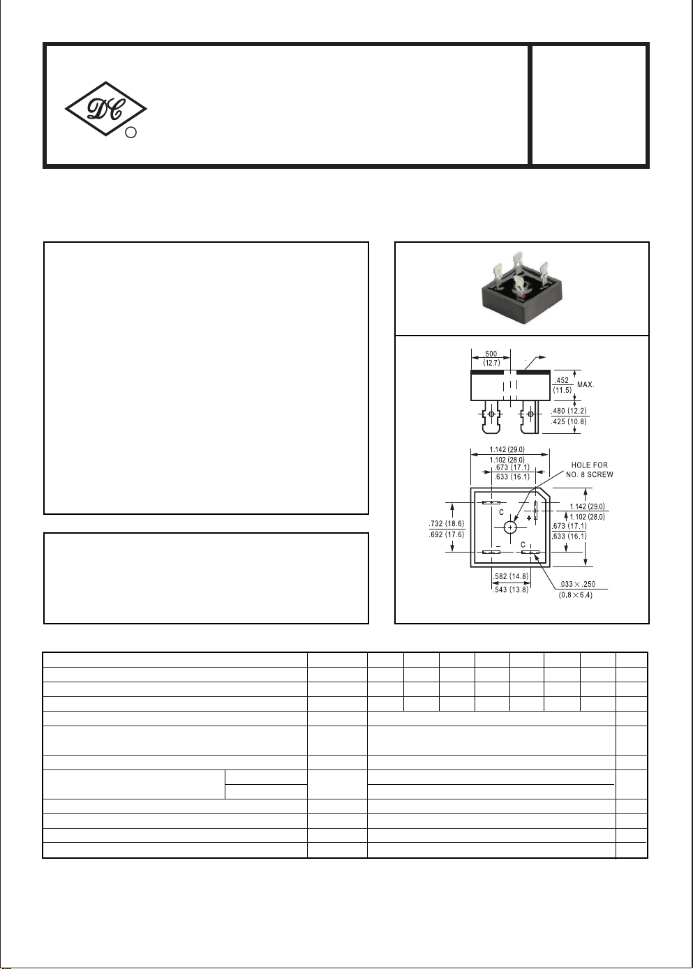
SINGLE-PHASE SILICON BRIDGE RECTIFIER
VOLTAGE RANGE - 50 to 1000 Volts CURRENT - 15 Amperes
FEATURES
* Plastic case with heatsink for Maximum Heat Dissipation
* Surge overload ratings-300 Amperes
* Low forward voltage drop
BR-25
METAL HEAT SINK
TYP
MECHANICAL DATA
* Case: Molded plastic with heatsink
* Epoxy: UL 94V-0 rate flame retardant
* Terminals: Plated .25"(6.35mm) Faston lugs, Solderable per
MIL-STD-202E, Method 208 guaranteed
* Polarity: As marked
* Mounting position: Any
* Weight: 30 grams
MAXIMUM RATINGS AND ELECTRICAL CHARACTERISTICS
Ratings at 25oC ambient temperature unless otherwise specified.
Single phase, half wave, 60 Hz, resistive or inductive load.
For capacitive load, derate current by 20%.
Dimensions in inches and (millimeters)
SYMBOL
Maximum Recurrent Peak Reverse Voltage
Maximum RMS Bridge Input Voltage
Maximum DC Blocking Voltage
Maximum Average Forward Rectified Output Current at Tc = 55oC
Peak Forward Surge Current 8.3 ms single half sine-wave
superimposed on rated load (JEDEC Method)
Maximum Forward Voltage Drop per element at 7.5A DC
Maximum DC Reverse Current at Rated
DC Blocking Voltage per element
I2t Rating for Fusing (t<8.3ms) I2t 374 A2Sec
Typical Junction Capacitance ( Note1)
Typical Thermal Resistance (Note 2)
Operating and Storage Temperature Range
NOTES : 1.
Measured at 1 MHZ and applied reverse voltage of 4.0 volts
2. Thermal Resistance from Junction to Case per leg.
@TA= 25oC
@TA= 100oC
V
V
RθJC
TJ,T
BR1505 BR151 BR152 BR154 BR156 BR158 BR1510
V
I
RRM
RMS
DC
I
O
FSM
V
I
R
C
F
J
STG
50 200 400100 600 800 1000
35 140 28070 420 560 700
50 200 400100 600 800 1000 Volts
15
300
1.1
10
500
300 pF
2.5 0C
-55 to + 150
UNITS
uAmps
244
Volts
Volts
Amps
Amps
Volts
/W
0
C
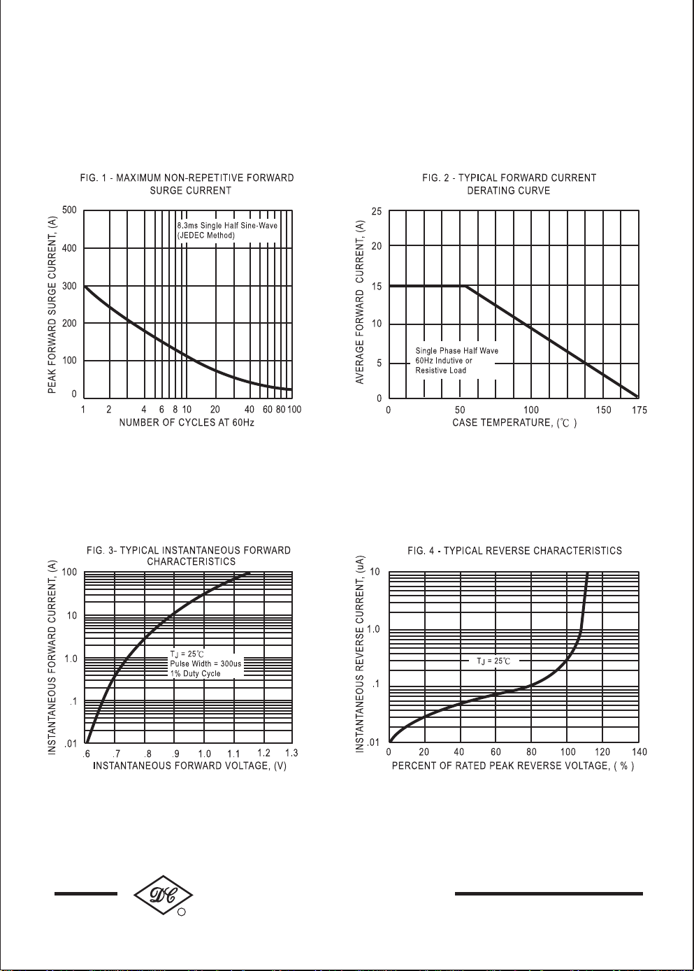
RATING AND CHARACTERISTIC CURVES ( BR1505 THRU BR1510 )
NEXT
BACK
EXIT
BACK
EXIT
EXIT
DC COMPONENTS CO., LTD.
R
245
 Loading...