

DCCOM BR1010, BR108, BR106, BR101, BR1005 Datasheet
...
DC COMPONENTS CO., LTD.
NEXT
BACK
EXIT
BACK
EXIT
EXIT
R
RECTIFIER SPECIALISTS
BR1005
THRU
BR1010
TECHNICAL SPECIFICATIONS
VOLTAGE RANGE - 50 to 1000 Volts
OF
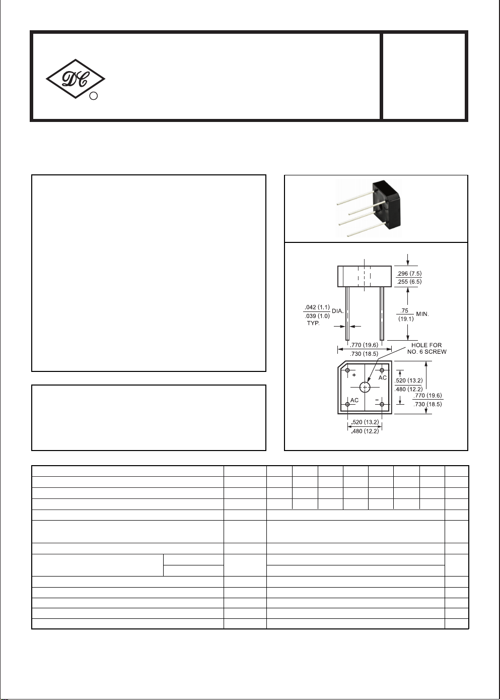
SINGLE-PHASE SILICON BRIDGE RECTIFIER
FEATURES
* Surge overload rating: 200 Amperes peak
* Low forward voltage drop
MECHANICAL DATA
* Case: Molded plastic
* Epoxy: UL 94V-0 rate flame retardant
* Lead: MIL-STD-202, Method 208 guaranteed
* Polarity: Symbols molded or marked on body
* Mounting position: Any
* Weight: 6.9 grams
MAXIMUM RATINGS AND ELECTRICAL CHARACTERISTICS
Ratings at 25oC ambient temperature unless otherwise specified.
Single phase, half wave, 60 Hz, resistive or inductive load.
For capacitive load, derate current by 20%.
Dimensions in inches and (millimeters)
CURRENT - 10 Amperes
BR-8/10
SYMBOL
Maximum Recurrent Peak Reverse Voltage
Maximum RMS Voltage
Maximum DC Blocking Voltage
Maximum Average Forward Rectified Output Current at
Peak Forward Surge Current 8.3 ms single half sine-wave
superimposed on rated load (JEDEC Method)
Maximum Forward Voltage Drop per element at 5.0A DC
Maximum DC Reverse Current at Rated
DC Blocking Voltage per element
I2t Rating for Fusing (t<8.3ms) I2t 166 A2Sec
Typical Junction Capacitance ( Note1)
Typical Thermal Resistance (Note 2)
Operating Temperature Range
Storage Temperature Range
NOTES : 1.
Measured at 1 MHZ and applied reverse voltage of 4.0 volts
2. Thermal Resistance from Junction to Ambient and from junction to lead mounted on P.C.B. with 0.5 x 0.5" (13x13mm) copper pads.
Tc = 50oC
= 25oC
@T
A
@TC= 100oC
V
V
T
BR1005 BR101 BR102 BR104 BR106 BR108 BR1010
RRM
RMS
V
DC
O
I
I
FSM
V
F
I
R
C
RθJA
T
J
STG
50 100 200 400 600 800 1000
7035 140 280 420 700
100
50 200 400 600 800 1000
10
200
1.1
10
500
J
200 pF
21 0C
-55 to + 125
-55 to + 150
UNITS
560
uAmps
240
Volts
Volts
Volts
Amps
Amps
Volts
/W
0
C
0
C
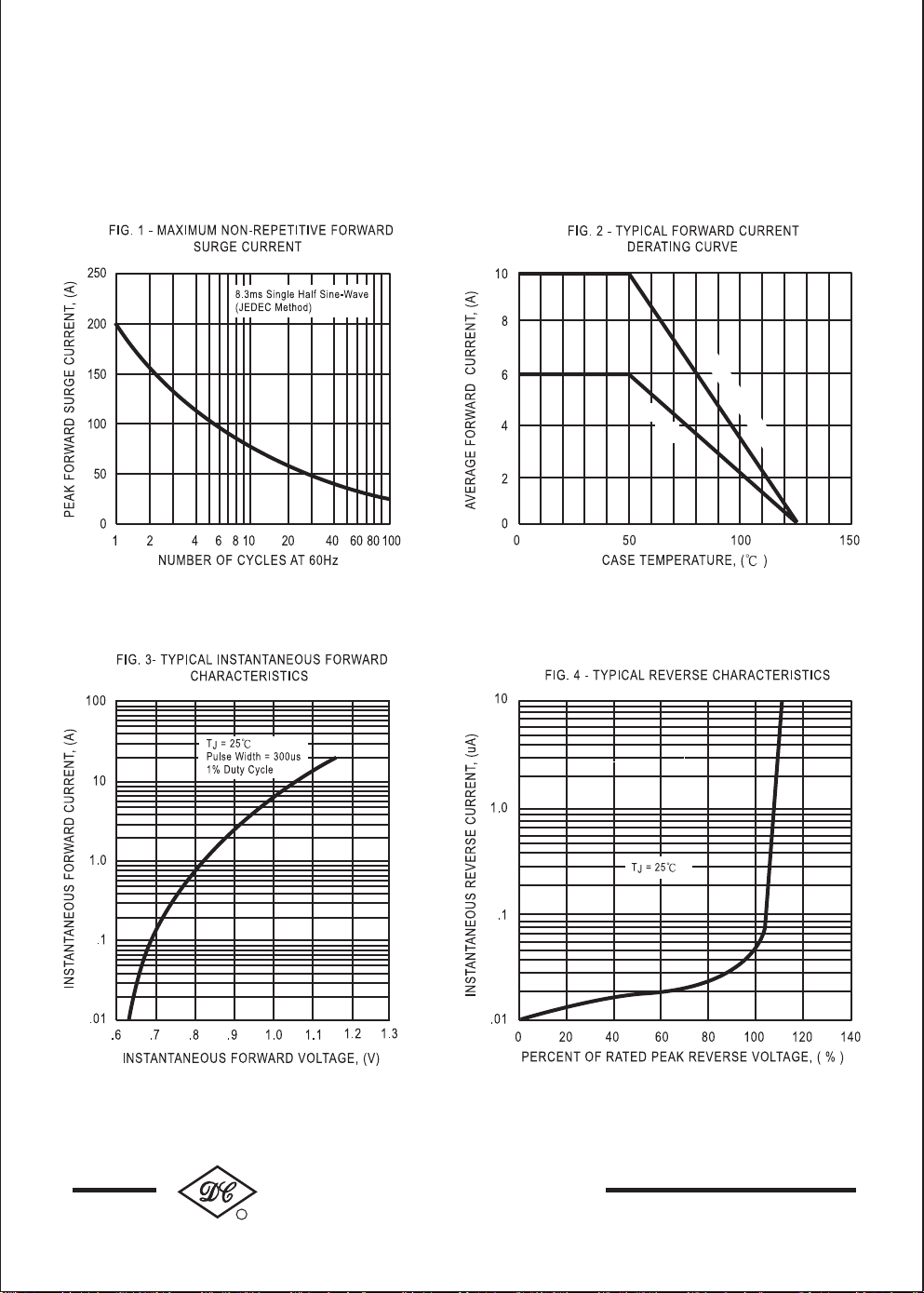
RATING AND CHARACTERISTIC CURVES (BR1005 THRU BR1010)
NEXT
BACK
EXIT
BACK
EXIT
EXIT
Heat-Sink Mounting
PC Board Mounting
DC COMPONENTS CO., LTD.
R
241
 Loading...