

dbx 160S Owner's Manual

¨
Stereo
Compressor/Limiter
160S
Owner’s Manual
Mode d’emploi
Bedienungsanleitung
Modo de empleo

WARNING
FOR YOUR PROTECTION, PLEASE READ THE FOLLOWING:
WATER AND MOISTURE:Appliance should not be used near water (e.g. near a ba thtub, wash-
bowl, kitchen sink, laundry tub,in a wet basement, or near a swimming pool,etc). Care should
be taken so that objects do not fall and liquids are not spilled into the enclosure through openings.
POWER SOURCES: The appliance should be connected to a power supply only of the type
described in the operating instructions or as marked on the appliance.
GROUNDING OR POLARIZATION: Precautions should be taken so that the grounding or polarization means of an appliance is not defeated.
POWER CORD PROTECTION: Power supply cords should be routed so that they are not likely to
be walked on or pinched by items placed upon or against them, paying particular attention to
cords at plugs, convenience receptacles, and the point where they exit from the appliance.
SERVICING: To reduce the risk of fire or electric shock, the user should not attempt to service
the appliance beyond that described in the operating instructions. All other servicing should be
referred to qualified service personnel.
FOR UNITS EQUIPPED WITH EXTERNALLY ACCESSIBLE FUSE RECEPTACLE: Replace fuse
with same type and rating only.
MULTIPLE-INPUT VOLTAGE: This equipment may require the use of a different line cord,attachment plug,or both, depending on the available power source at installation.Connect this equipment only to the power source indicated on the equipment rear panel.To reduce the risk of fire
or electric shock, refer servicing to qualified ser vice personnel or equivalent.
SAFETY INSTRUCTIONS
NOTICE FOR CUSTOMERS IF YOUR UNIT IS EQUIPPED WITH A POWER CORD.
WARNING: THIS APPLIANCE MUST BE EARTHED.
The cores in the mains lead are coloured in accordance with the following code:
GREEN and YELLOW - Earth BLUE - Neutral BROWN - Live
As colours of the cores in the mains lead of this appliance may not correspond with
the coloured markings identifying the terminals in your plug, proceed as follows:
• The core which is coloured green and yellow must be connected to the terminal in the plug marked with the letter E, or with the earth symbol, or
coloured green, or green and yellow.
• The core which is coloured blue must be connected to the terminal marked
N or coloured black.
• The core which is coloured brown must be connected to the terminal
marked L or coloured red.
This equipment may require the use of a different line cord, attachment plug, or
both, depending on the available power source at installation. If the attachment
plug needs to be changed, refer servicing to qualified service personnel who
should refer to the table below. The green/yellow wire shall be connected directly to the unit's chassis.
WARNING: If the ground is defeated, certain fault conditions in the unit or in the
system to which it is connected can result in full line voltage between chassis and
earth ground. Severe injury or death can then result if the chassis and earth
ground are touched simultaneously.
U.K. MAINS PLUG WARNING
A
moulded mains plug that has been cut off from the cord is unsafe. Discard
the mains plug at a suitable disposal facility. NEVER UNDER ANY CIRCUM-
STANCES SHOULD YOU INSERT A DAMAGED OR CUT MAINS PLUG INTO A
13 AMP POWER SOCKET. Do not use the mains plug without the fuse cover
in place. Replacement fuse covers can be obtained from your local retailer.
Replacement fuses are 13 amps and MUST be ASTA approved to BS1362.
The symbols shown above are internationally accepted symbols that warn of
potential hazards with electrical products. The lightning flash with arrowpoint in
an equilateral triangle means that there are dangerous voltages present within the
unit. The exclamation point in an equilateral triangle indicates that it is necessary
for the user to refer to the owner’s manual.
These symbols warn that there are no user serviceable parts inside the unit. Do
not open the unit. Do not a ttempt to service the unit yourself. Refer all servicing
to qualified personnel. Opening the chassis for any reason will void the manufacturer’s warranty. Do not get the unit wet. If liquid is spilled on the unit, shut it off
immediately and take it to a dealer for service. Disconnect the unit during storms
to prevent damage.
CAUTION
ELECTROMAGNETIC COMPATIBILITY
This unit conforms to the Product Specifications noted on the Declaration of Conformity.
Operation is subject to the following two conditions:
• this device may not cause harmful interference, and
• this device must accept any interference received, including interference that
may cause undesired operation.
Operation of this unit within significant electromagnetic fields should be avoided.
• use only shielded interconnecting cables.
DECLARATION OF CONFORMITY
ManufacturerÕs Name: dbx Professional Products
ManufacturerÕs Address: 8760 S. Sandy Parkway
Sandy, Utah 84070, USA
declares that the product:
dbx 160S
conforms to the following Product Specifications:
Safety: EN 60065 (1993)
IEC65 (1985) with Amendments 1, 2, 3
EMC: EN 55013 (1990)
EN 55020 (1991)
Supplementary Information:
The product herewith complies with the requirements of
the Low Voltage Directive 73/23/EEC and the EMC
Directive 89/336/EEC as amended by Directive
93/68/EEC.
dbx Professional Products
Vice-President of Engineering
8760 S. Sandy Parkway
Sandy, Utah 84070, USA
March 31, 1997
European Contact: Your Local dbx Sales and Service Office or
International Sales Office
68 Sheila Lane
Valparaiso, Indiana
46383, USA
Tel: (219) 462-0938
Fax: (219) 462-4596
RISK OF ELECTRIC SHOCK
DO NOT OPEN
ATTENTION: RISQUE DE CHOC ELECTRIQUE - NE PAS OUVRIR
WARNING: TO REDUCE THE RISK OF FIRE OR ELECTRIC
SHOCK DO NOT EXPOSE THIS EQUIPMENT TO RAIN OR MOISTURE
CONDUCTOR
L
N
E
LIVE
NEUTRAL
EARTH GND
WIRE COLOR
Normal Alt
BROWN
BLUE
GREEN/YEL
BLACK
WHITE
GREEN

Introduction . . . . . . . . . . . . . . . . . . . . . . . . . . . . . . . . . . . . . . . . . . . . . . . . . . . . . . . . . .3
Why you need compression . . . . . . . . . . . . . . . . . . . . . . . . . . . . . . . . . . . . . . . .3
The difference between compressors and limiters
. . . . . . . . . . . . . . . . . . . . . .4
The compression and limiting effects
. . . . . . . . . . . . . . . . . . . . . . . . . . . . . . . . .5
Limiters and PeakStopPlus™
. . . . . . . . . . . . . . . . . . . . . . . . . . . . . . . . . . . . . . . .6
Connection To Your System . . . . . . . . . . . . . . . . . . . . . . . . . . . . . . . . . . . . . . . . .9
Operating Controls
. . . . . . . . . . . . . . . . . . . . . . . . . . . . . . . . . . . . . . . . . . . . . . . . . .10
Front Panel Description . . . . . . . . . . . . . . . . . . . . . . . . . . . . . . . . . . . . . . . . . . . .10
Rear Panel Description
. . . . . . . . . . . . . . . . . . . . . . . . . . . . . . . . . . . . . . . . . . . . .15
Operating Notes . . . . . . . . . . . . . . . . . . . . . . . . . . . . . . . . . . . . . . . . . . . . . . . . . . . . . .19
OverEasy® and hard knee . . . . . . . . . . . . . . . . . . . . . . . . . . . . . . . . . . . . . . . . . .19
Using the Compression Control
. . . . . . . . . . . . . . . . . . . . . . . . . . . . . . . . . . . . . .19
Using the Stereo Couple Switch
. . . . . . . . . . . . . . . . . . . . . . . . . . . . . . . . . . . . .20
Using the Auto Switch
. . . . . . . . . . . . . . . . . . . . . . . . . . . . . . . . . . . . . . . . . . . . .20
Setting the Attack and Release Controls
. . . . . . . . . . . . . . . . . . . . . . . . . . . . . . .20
Using PeakStop®/PeakStopPlus™
. . . . . . . . . . . . . . . . . . . . . . . . . . . . . . . . . . . .21
Specific Applications
. . . . . . . . . . . . . . . . . . . . . . . . . . . . . . . . . . . . . . . . . . . . . . .22
Sidechain Applications
. . . . . . . . . . . . . . . . . . . . . . . . . . . . . . . . . . . . . . . . . . . . .23
Technical Support/Factory Service . . . . . . . . . . . . . . . . . . . . . . . . . . . . . . . . . .27
Warranty
. . . . . . . . . . . . . . . . . . . . . . . . . . . . . . . . . . . . . . . . . . . . . . . . . . . . . . . . . . . . .27
Block Diagram
. . . . . . . . . . . . . . . . . . . . . . . . . . . . . . . . . . . . . . . . . . . . . . . . . . . . . .108
Specifications
. . . . . . . . . . . . . . . . . . . . . . . . . . . . . . . . . . . . . . . . . . . . . . . . . . . . . . .109
Warranty Registration Card
contents
Manual
160S


Why You Need A Compressor
A remarkable feature of the human ear is that it can detect an extremely wide range of amplitude
changes - from the slightest whisper to a deafening clap of thunder. If one tries to record or reproduce
this wide spectrum of sound with the help of amplifiers, cassette recorders, records, or even digital
recorders, one is immediately restricted by the physical limitations of electronic and acoustic sound
reproduction technology.
The useable dynamic range of electronic audio equipment is limited as much at low levels as at high
levels. The thermal noise of electrons in the components results in an audible noise floor and thus represents the bottom limit of the transmission range. In such equipment, this is referred to as “hysteresis”.
Referring to any magnetic media, hysteresis is the amount of electrical impulse it takes for the tape
recorder to begin to rearrange the magnetic particles of the tape (record signal onto the tape). The more
energy it takes, the more noise is introduced onto the tape, making the noise floor more audible. The
amount of hysteresis varies depending on the brand of tape used, and depends on the materials used
in the manufacture of the tape.
When magnetic tape was first used to record audio, hysteresis was a real concern, because it made the
useable dynamic range of magnetic tape very narrow. In the early 1960s, it was discovered that if a tape
recorder supplied an extremely high frequency tone to its record head (much higher than the magnetic
tape could possibly record), the tape’s hysteresis was greatly reduced, or, it took less electrical activity
to start to rearrange the magnetic particles of the tape. The result: a much lower noise floor level and a
wider dynamic range. This tone is called a “bias tone” or “bias frequency.” Today tape manufacturers
produce tape optimized for specific bias frequencies, and studio technicians align tape recorders’ heads
according to these specifications, in order to take full advantage of the tape recorders’ electronics, and
the magnetic tape’s ability to record sound on its magnetic particles.
The upper limit of useable dynamic range is determined by the levels of the internal operating voltages;
if they are exceeded, audible signal distortion is the result. Although in theory the useable dynamic range
sits between these two limits, it is considerably smaller in practice, since a certain reserve must be maintained to avoid distortion of the audio signal if sudden noise peaks occur. Technically speaking, we refer
to this reserve as headroom--usually about 10-20dB. A reduction of the operating level would allow for
greater headroom, i.e. the risk of signal distortion due to high level peaks would be reduced. However
at the same time, the basic signal to noise ratio of the program material would be increased significantly. It is therefore useful to keep the operating level as high as possible without risking signal distortion
in order to achieve optimum transmission quality. It is possible to further improve the transmission quality by constantly monitoring the program material with the aid of a volume fader, which manually
changes the level of the program material. During low passages the gain is increased, and during loud
passages the volume is decreased. Of course it is fairly obvious that this kind of manual control is rather
restrictive; it is difficult to detect signal peaks and almost impossible to level them out. Manual control
is simply not fast enough to be satisfactory.
The need therefore arises for a fast acting automatic gain control system which will constantly monitor
the signals and which will always adjust the gain to maximize the signal-to-noise ratio without incurring
signal distortion. This device is called a compressor or limiter.
3
Introduction
160S
The Difference Between Compressors and Limiters
By measuring the dynamic range of musical instruments in live recording situations, you will experience
extreme amplitudes which will often lead to overload in subsequent signal processing equipment.
Especially in broadcasting and digital recording, these signal peaks can lead to heavy distortion. To avoid
this kind of distortion or, to avoid loudspeakers being damaged by overload, compressors and limiters
are used.
The principle function of these devices is automatic gain control, as mentioned in the previous paragraphs, which reduces the the amplitude of loud passages and therefore restricts the original signal
dynamics within a desired range. This is useful, especially in conjunction with microphone recording
techniques, to compensate for level changes which are caused by inconsistent microphone techniques
on the part of the player, or to restrict the natural dynamic range of voices or intruments to achieve a
more even level.
Although compressors and limiters perform similar tasks, one essential point makes them different:
Limiters abruptly limit the signal above a certain level, while compressors control the signal “gently” over
a wide range. A limiter continuously monitors the signal and intervenes as soon as an adjustable level
is exceeded. This level is called the “threshold”. Any signal exceeding this threshold level will be immediately held below the set threshold level.
A compressor also monitors the program material continuously and also has a set threshold level.
However, in contrast to the limiter, signals exceeding the threshold are not reduced abruptly, but gradually. Above the threshold the signal is reduced in level relative to the amount the signal exceeds this
point.
Generally, threshold levels for compressors are set below the normal operating level to allow for the
upper dynamics to be musically compressed. For limiters, the threshold point is set above the normal
operating level in order to provide peak signal limiting and thus protects subsequent equipment.
4
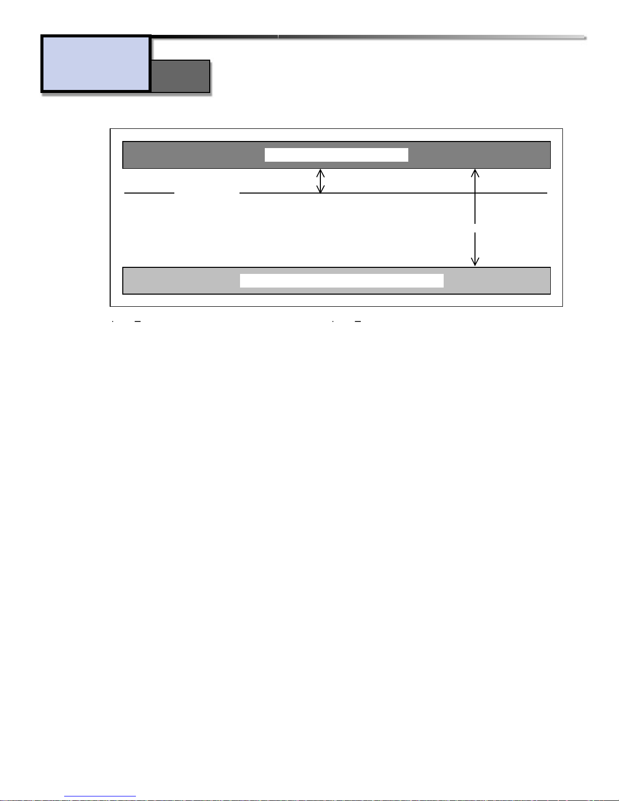
Dynamic
Range
Introduction
160S
Clipping
Noise Floor
Operating Level
Audio levels below here are not heard, because of noise
Clipped signal heavily distorted
Headroom
Useable dynamic range
The Compression and Limiting Effects
On a compressor, there is a relationship between the input signal, and the threshold level, input, output, and ratio settings. Look at an input signal applied to the inputs of two compressors. The threshold
level of the second unit is set ten decibels higher than the threshold of the first unit. Since a compressor only affects signals that exceed the threshold level, it is obvious that the signal of the first compressor will be compressed more, because it exceeds the threshold level more than the level of the second
unit, because the second compressor’s threshold level is set higher.
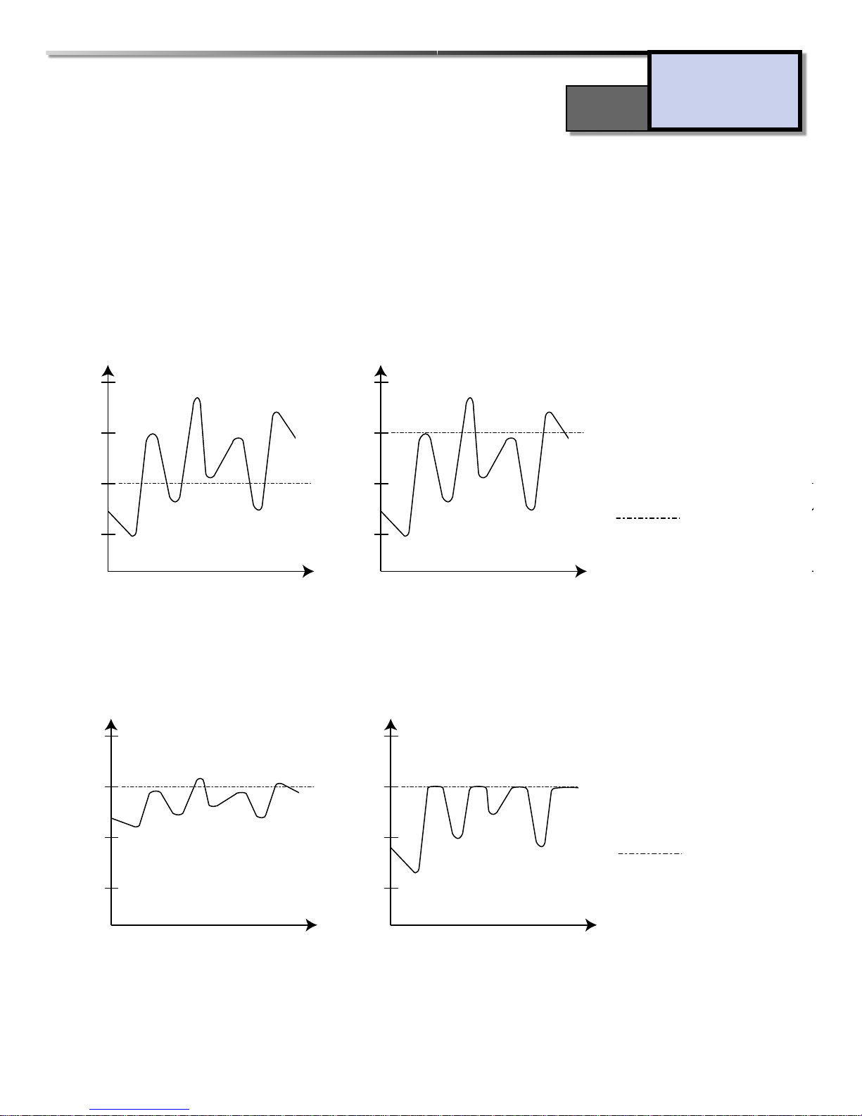
The difference between compression and limiting is shown visually below. In the first diagram below,
compression “squashes” the signal. Its peaks are lowered, but the overall level of the signal is raised due
to applied make-up gain (Output Gain). In the second diagram, the peaks are lowered to the threshold
level, but the rest of the signal has not been altered.
Obviously, there is a large difference between these two signals in relation to their dynamic range and
the processed signal. In the third figure, it is shown to have been compressed, and in the fourth figure,
it has been limited.
5
Input of compressors at
different threshold settings.
= th reshold
Introduction
Difference in output of
compressors and limiters.
= th reshold
160S
input
dBu
input
dBu
input
dBu
+10
0
-10
-20
time
output
dBu
+10
0
-10
Figure 1
+10
-10
-20
+10
0
output
0
-10
time
dBu
+10
0
-10
-20
Figure 2 Figure 1
time
-20
time
Figure 3 Figure 4
-20
time

6
Furthermore, it is interesting to note that by comparing the input and output waveforms for the compressed mode, the quietest sections of the input signal have been effectively raised in level, whereas the loudest sections have been effectively decreased in level. The overall effect is that both ends
of the dynamic range have been pushed toward the middle. This squashing effect of compression is
important to remember and highlights the major difference between compressing and limiting.
Compressing and limiting differ in one more aspect: the dynamic settings for attack and release times.
Attack time is defined as the time taken to for a compressor to respond to program levels which have
exceeded the threshold point. Release time is the amount of time a compressor takes to return the
program level to its original level, after the last excursion over the threshold point. For compression,
a preferably longer attack and release time are generally the best in order to keep the overall output
signal within a specified dynamic range. For limiting applications, considerably shorter attack and
release times are necessary to control fast transient signals or to increase headroom.
To achieve inaudible compression, it is advisable to work with program dependent attack and release
times. The advantage of program dependent compression is most apparent when processing musical material that is varied.
The dbx 160S Stereo Compressor is suitable for all applications because of its ability to be manually
set at both attack and release parameters.
Limiters and PeakStopPlus™
Lower frequencies work best when compressed with slower attack times. When compressing a mix
that includes a wide range of frequencies, a compromise is made when setting the attack time. The
attack setting would generally suit the lowest frequency components of the material. For general
dynamic range control with a compressor, this is of no serious consequence.
However, in a “limiting” situation, where we are restricting the peaks of our signal to a maximum
operating level to avoid distortion in subsequent devices, a slow attack time is not acceptable. This
would result in very fast high frequency signal transients passing through unaffected by gain reduction. These transients could then cause distortion in the following equipment such as tape recorders
and radio transmitters. It is therefore necessary to choose an attack time which is as close to “zero”
attack as possible, independent of the frequency.
This makes the limiter necessary, and it’s why we include a peak limiter on almost all of our compression products. The dynamics of the dbx limiters are set to handle these fast transients through a
process called PeakStop® and the newer, improved two-stage process called PeakStopPlus®.
The first stage of PeakStopPlus is the Instantaneous Transient Clamp™ which clamps the signal with a soft logarithmic clamp function. This logarithmic function assures that the signal will not exceed the level set by the
PeakStopPlus™ LEVEL control by more than 2 dB typically, and that it will not introduce harsh artifacts. The
second stage is a unique program limiter featuring Intelligent Predictive Limiting™. Its function is to monitor
the input signal and intelligently predict the amount of gain reduction needed to keep the output signal below
the ceiling set by the Instantaneous Transient Clamp™. Note, since the PeakStopPlus™ limiter is a fail-safe limiter it must come after the OUTPUT GAIN control. If the output gain is set too high as compared to the
Introduction
160S

7
PeakStopPlus™ Level control, continuous limiting can occur . While PeakStopPlus™ is typically used as a protective function, creative effects can be achieved by intentionally driving the signal into heavy PeakStopPlus™
limiting. Great care has gone into the design of the PeakStopPlus™ limiter to keep it acoustically transparent.
Appropriate use of it can protect your gear while keeping the signal free of artifacts.
For best results the Limiter functions of your compressor should be used in conjunction with the
Compressor functions.
When we at dbx decided to make a premium compressor that would perform to the industry’s highest standards, it became readily obvious that every component and design strategy had to be chosen
with high-performance foremost in mind. After the evolutionary process of engineering design and
implementation was complete, the result was stunning. Here is a partial list of the features found on
the 160S. You won’t hear about most of them anywhere else, but they are critical to the amazing
specs, comprehensive functionality, and visionary design of the 160S Stereo Compressor.
• New dbx V8™ VCA module exhibits a dynamic range of 127dB
with extremely low distortion!
• V8™ VCA is encased in a specially-designed zinc-aluminum housing for shielding and thermal characteristics. This allows for peak
performance of the VCA in any environment.
• Precision 0.1% and 1% metal film resistors.
• Gold-palladium-nickel board-to-board connectors.
• Jensen® transformers.
• Gold-plated Neutrik® XLR connectors.
• Rare earth magnet relays with gold contacts in a hermetically
sealed nitrogen environment.
• Military-grade glass epoxy circuit boards.
• Double-shielded Toroid transformer ensures no self-generated
power supply noise enters the audio path.
• High-drive output transformers are capable of driving 1000 feet of
Belden 8451 cable to +30dBm.
• Striking blue custom-machined, 1/4” thick front panel.
• Hand-crafted, solid aluminum knobs.
• LEDs mounted in machined, stainless steel housings.
• Custom dbx VU meters with peak indicators.
• Heavy-gauge chassis.
• Switchable OverEasy®/hard knee characteristics enable the 160S to
sound like the traditional 165A as well as the old and still popular
160.
• Program dependent Auto mode, or fully variable attack and
release.
• PeakStop/PeakStopPlus™ switchable limiting topologies, the perfect complement to the 160S feature set.
• Sidechain capabilities, switchable from the front panel.
Introduction
160S
 Loading...