

Page 1
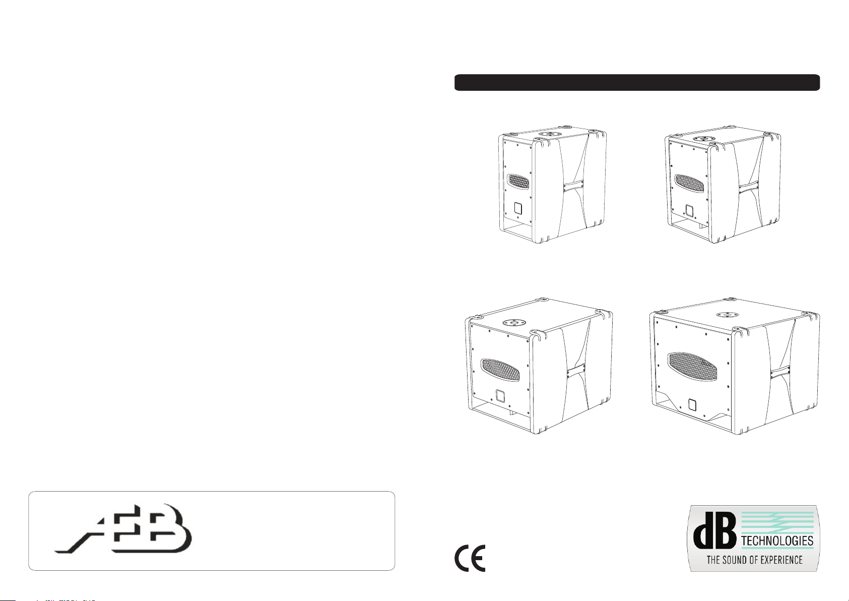
SUB D
ACTIVE DIGITAL SUBWOOFERS
H.E.T. Series
A.E.B. INDUSTRIALE s.r.l.
Via Brodolini, 8 - 40056 Crespellano (Bo) - ITALIA
Tel. + 39 051 969870 - Fax. + 39 051 969725
Internet: www.dbtechnologies.com
E-mail: info@dbtechnologies-aeb.com
SUB 28D
SUB 05D
MANUALE D’USO - Sezione 1
USER MANUAL - Section 1
BEDIENUNGSANLEITUNG - Abschnitt 1
CARACTERISTIQUES TECHNIQUES - Section 1
DESIGNED & DEVELOPED in ITALY
Made in China
COD. 420120181 REV.1
SUB 12D
SUB 808D
Page 2

DESCRIZIONE
I diffusori SUB28D, SUB 12D, SUB 05D e SUB 808D sono subwoofer realizzati con
tecnologia ibrida H.E.T. (Hybrid Enclosure Technology), sviluppata nei laboratori dB
Technologies.
Il box infatti è realizzato in legno multistrato leggero, rivestito in PVC ed i fianchi sono in
polipropilene.
I diffusori della serie “SUB D" H.E.T. utilizzano moduli amplificatori digitali multicanale di
ultima generazione DIGIPACK .
Questi amplificatori, ad alta efficienza, permettono di ottenere elevate potenze di uscita
con ingombri ridotti. Grazie alla bassa potenza dissipata il raffreddamento del modulo
amplificatore avviene in modo statico, evitando l’uso di ventola.
Il preamplificatore digitale con DSP (Digital Signal Processing) gestisce la risposta in
frequenza, il limiter, l’incrocio audio in caso di più diffusori collegati.
La regolare accensione del diffusore è garantita da una procedura di inizializzazione;
durante questa fase di test, entrambe i LED “LIMITER” e “ON SIGNAL” rimangono accesi
contemporaneamente per circa 2 sec.
Al termine della procedura di avvio il LED verde “ON SIGNAL” lampeggia lentamente, nel
caso di assenza di segnale.
Durante il normale funzionamento il LED verde “ON SIGNAL” funge da Vu-Meter
monitorando il livello audio riprodotto.
Il LED rosso "LIMITER" si illumina per indicare l'intervento del circuito limitatore, il quale
evita la distorsione dell'amplificatore e protegge gli altoparlanti da sovraccarichi.
Manuale d’usoManuale d’uso
I SUB D (H.E.T.) sono subwoofers attivi studiati per sonorizzare ambienti medio grandi;
sono costruiti utilizzando la tipologia “BAND PASS” che permette di ottenere alte pressioni
acustiche in dimensioni ridotte.
Questi diffusori sono stati progettati per funzionare in modalità stereo o modalità mono.
Tramite due pulsanti è possibile impostare la risposta in frequenza e la rotazione di fase (0°
oppure 180°). I segnali di uscita possono essere link oppure pilotati dall’uscita XOVER.
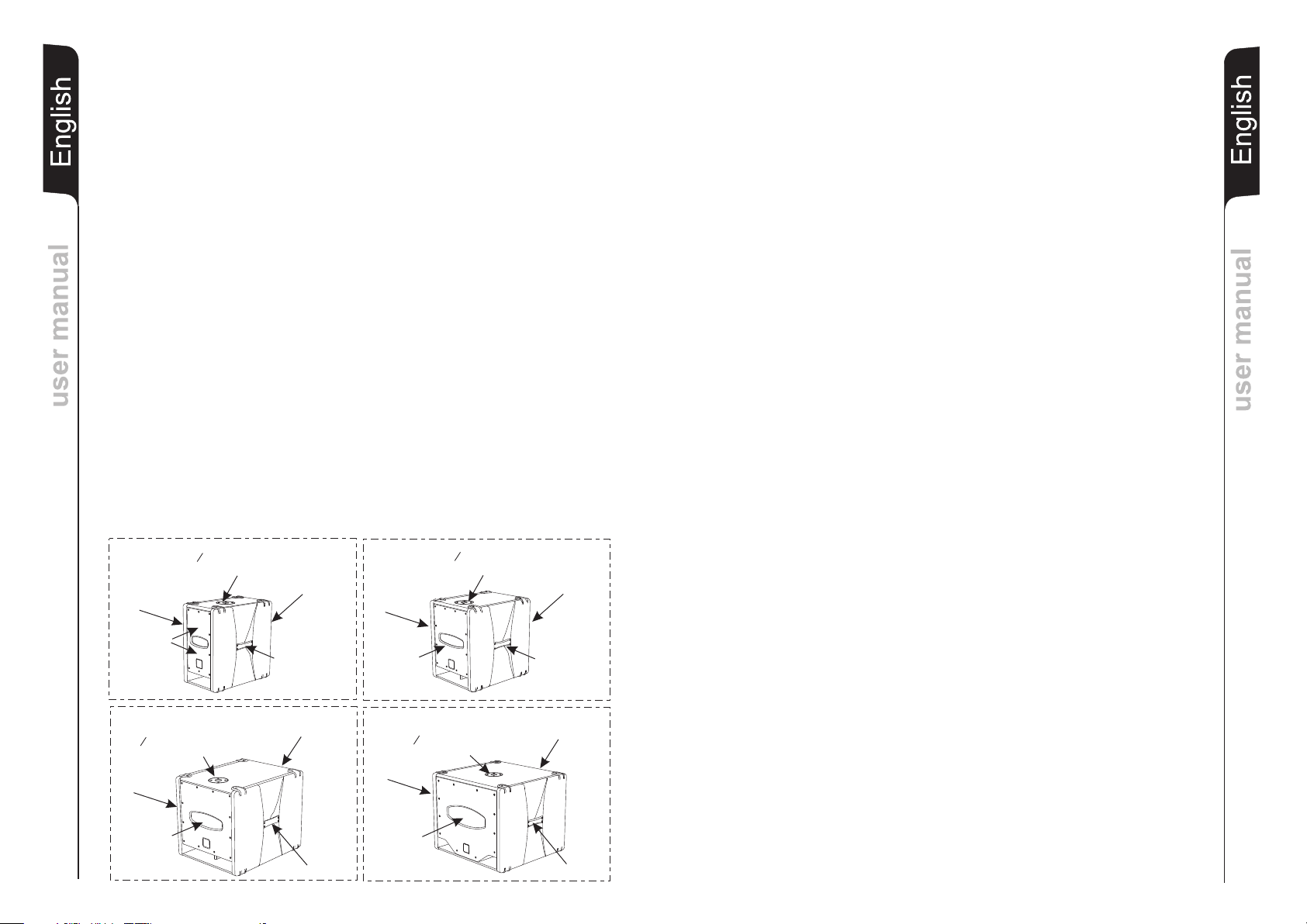
I diffusori SUB D (H.E.T.) sono stati progettati per l'utilizzo in appoggio e per facilitarne
l'utilizzo, l'installazione e il trasporto, sono provvisti di:
- 2 maniglie plastiche laterali ,
- supporto piantana standard (D.36mm) sul la parte superiore del box.
SUB 28D
SUPPORTO PIANTANA Æ 36mm
MANIGLIA
WOOFERS
AMPLIFICATORE
MANIGLIA
SUB 12D
SUPPORTO PIANTANA Æ 36mm
MANIGLIA
WOOFER
AMPLIFICATORE
MANIGLIA
COMANDI E FUNZIONI
Pannello Amplificatore (Rif. pag.17)
1) CONNETTORI INGRESSO " BALANCED INPUT 1” e " BALANCED INPUT 2”
Connettori “XLR” di ingresso bilanciato a livello linea .
2) CONNETTORI DI USCITA "OUT 1”e
I connettori “XLR” sono utilizzati per inviare il segnale audio ad un altro diffusore
amplificato.
Il tipo di segnale è selezionabile tramite l’interruttore” LINK/XOVER” (8)
3) INDICATORE LUMINOSO “LIMITER”
Questo indicatore s’illumina di colore rosso per indicare l'intervento del circuito
limitatore interno, il quale evita la distorsione dell'amplificatore e protegge gli
altoparlanti da sovraccarichi.
4) INDICATORE LUMINOSO “ON SIGNAL”
Questo indicatore s'illumina di colore verde per indicare il corretto funzionamento
del diffusore. In caso di assenza di segnale il led lampeggia lentamente.
Nel normale funzionamento il led funge da Vu-Meter monitorando il livello audio.
5) CONTROLLO SENSIBILITA’ INGRESSO “SUBWOOFER SENSITIVITY”
Questo controllo regola la sensibilità del segnale in ingresso all’amplificatore.
Tale controllo non influisce sul livello dell’uscita “OUT 1” e “OUT 2”
6) SELETTORE “PHASE”
Questo interruttore a due posizioni permette la rotazione di 180°del segnale audio
riprodotto dal subwoofer. La rotazione facilita l’ottimizzazione della riproduzione alle
basse frequenze anche nelle situazioni di installazioni difficili. Completata
l’installazione, riprodurre un brano musicale ed agire sull’interruttore per ottenere la
migliore resa acustica alle basse frequenze.
7) SELETTORE “SHAPE”
Questo interruttore permette di selezionare la risposta in frequenza del subwoofer.
E' possibile scegliere tra due configurazioni: una rende il suono più profondo e ricco
di bassi, l'altra per un suono ricco di "punch".
8) SELETTORE “LINK/XOVER”
Questo interruttore permette di selezionare il segnale da rilanciare sulle uscite “OUT
1” e “OUT 2”.
La posizione “LINK” permette di rilanciare lo stesso segnale di ingresso.
La posizione “XOVER” permette d’ inviare il segnale di ingresso tagliato alla
frequenza di 90Hz.
9) INTERRUTTORE GENERALE “POWER”
L’interruttore permette l’accensione e lo spegnimento del diffusore.
10) PORTA FUSIBILE “FUSE”
Alloggio per fusibile di rete.
11) PRESA DI ALIMENTAZIONE “MAINS ”
Consente la connessione del cavo di alimentazione fornito in dotazione.
"OUT 2”
Manuale d’usoManuale d’uso
SUB 05D
SUPPORTO PIANTANA Æ 36mm
MANIGLIA
WOOFER
1
AMPLIFICATORE
MANIGLIA
SUB 808D
SUPPORTO PIANTANA Æ 36mm
MANIGLIA
WOOFER
AMPLIFICATORE
MANIGLIA
CARATTERISTICHE
Raffreddamento
Il controllo termico è gestito dal DSP interno, che grazie ad un sensore controlla la
temperatura dell’amplificatore evitando il surriscaldamento limitandone il volume generale.
In caso di surriscaldamento (> 90°C) il volume decresce in funzione dell’aumento della
temperatura rendendo impercettibile la variazione.
Il corretto volume e tutte le funzioni verranno riprese automaticamente al raggiungimento
delle normali temperature di esercizio.
2
Page 3

INSTALLAZIONE DEL DIFFUSORE
ATTENZIONE
Installare il diffusore in modo stabile e sicuro, così da evitare qualsiasi condizione di
pericolo per l’incolumità di persone, strutture, animali o cose.
Per evitare condizioni di pericolo non sovrapporre fra loro più diffusori senza adeguati
sistemi di ancoraggio.
ItalianoItaliano
Nell’utilizzo all’aperto evitare luoghi esposti alle intemperie.
Il diffusore viene fornito dalla ditta costruttrice predisposto per l’utilizzo in appoggio.
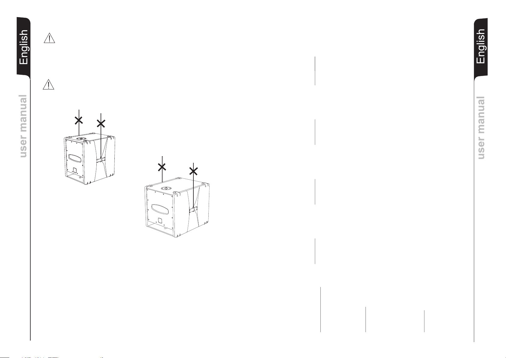
ATTENZIONE
Non utilizzare mai le maniglie per appendere il diffusore!
ItalianoItaliano
Manuale d’usoManuale d’uso
CLASSIFICAZIONE EMI
SUB 28D - SUB 12D - SUB 05D - SUB 808D
In accordo alle normative EN 55103, l'apparato è progettato e idoneo all'utilizzo in ambienti
Elettromagnetici E3 o inferiori (E2, E1).
3
SUB 28D SUB 12D SUB 05D SUB 808D
Trasformatore Toroidale
Amplificatore e processore
DATI TECNICI
Tipo alimentazione: Trasformatore Toroidale Trasformatore Toroidale Trasformatore Toroidale
Pre-Amplificatore: 24bit 48KHz DSP 24bit 48KHz DSP 24bit 48KHz DSP 24bit 48KHz DSP
Amplificatore: Classe-D 400 W Classe-D 400 W Classe-D 400 W Classe-D 500 W
Raffreddamento: Convenzione Convenzione Convenzione Convenzione
Controlli/limiter: RMS, Picco, Termico RMS, Picco, Termico RMS, Picco, Termico RMS, Picco, Termico
Frequenza X-over (taglio): 110 Hz, 24 dB/oct. 90 Hz, 24 dB/oct. 90 Hz, 24 dB/oct. 90 Hz, 24 dB/oct.
SPL massimo: 125 dB 127 dB 129 dB 131 dB
Risposta in frequenza -3 dB: 45 Hz - 150 Hz 40 Hz - 150 Hz 30 Hz - 150 Hz 29 Hz - 150 Hz
Dati Audio
Componenti: 2x8“ Woofer - 1,5“ voice coil 1x12“ Woofer - 2,5“ voice coil 1x15“ Woofer - 2,5“ voice coil 1x18“ Woofer - 2,5“ voice coil
Ingressi: 2 x XLR femmina Bilanc. 2 x XLR femmina Bilanc. 2 x XLR femmina Bilanc. 2 x XLR femmina Bilanc.
Uscite: 2 x XLR maschio Bilanc. 2 x XLR maschio Bilanc. 2 x XLR maschio Bilanc. 2 x XLR maschio Bilanc.
Sensibilità in ingresso: max 0dBu max 0dBu max 0dBu max 0dBu
Connettore alimentazione: IEC, VDE IEC, VDE IEC, VDE IEC, VDE
Corrente di accensione 15,2 A 15,2 A 15,2 A 19,3 A
Equipaggiamento meccanico
Supporto piantana: 36 mm lato superiore 36mm lato superiore 36 mm lato superiore 36 mm lato superiore
Maniglie: 2 (1 per lato) 2 (1 per lato) 2 (1 per lato) 2 (1 per lato)
Dimensione (Lx H x P): 290 x 520 x 505mm 390 x 520 x 505mm 490 x 520 x 615mm 640 x 520 x 615mm
Peso: 19,5 Kg 24 Kg 29,5 Kg 34,8 Kg
Manuale d’usoManuale d’uso
4
Page 4
DESCRIPTION
SUB28D, SUB12D, SUB05D and SUB808D sub-woofer speakers are realized with Hybrid
Enclosure Technology (H.E.T.), developed by the dB Technologies labs.
The box in fact is made in light multilayer wood, coated in PVC and the sides are in
polypropylene.
The speakers of “SUB D” H.E.T. series use multichannel digital power amplifiers of last
EnglishEnglish
user manualuser manual
generation DIGIPACK .
These highly efficient amplifiers provide high power with limited weight and dimension.
Thanks to the low power dissipated, the cooling of the amplifier module does not require a
fan.
The digital preamplifier with DSP (Digital Signal Processing) controls the audio crossover
of the acoustic components, the frequency response, the limiter, and the phase alignment.
The correct switch on of the amplifier is guaranteed by an initialization procedure; during
this test stage the LEDs (“LIMITER” and “ON SIGNAL”), located on the amplifier
module,stay on together for approx. 2 sec.
At the end of the switch on procedure, on the amplifier module, the “ON SIGNAL” green
LED flashes slowly, when there is signal absence.
During normal operation the “ON SIGNAL” green LED serves as Vu-meter monitoring the
audio level riproduced.
The "LIMITER" red LED lights up to indicate that the internal limiter circuit has tripped to
prevent amplifier distortion and protects the speakers against overloads.
SUB D (H.E.T.) are active sub-woofers designed for medium to large size rooms; are made
using “BAND PASS” so that high sound pressures can be achieved in compact dimensions.
These speakers are designed to function in stereo and in mono modes. It is possible to set
the frequency response and turning of phase (0° or 180°). The output signals can be linked
or controlled by X-OVER output.
For easy use, installation and transport, all subwoofers are provided with:
- 2 plastic handles on sides,
- standard (D.36mm) pole mount plate on top of box.
SUB 28D
HANDLE
WOOFERS
O 36mm PEDESTAL/
BRACKET HOUSING
AMPLIFIER
HANDLE
SUB 12D
HANDLE
WOOFER
O 36mm PEDESTAL/
BRACKET HOUSING
AMPLIFIER
HANDLE
CONTROLS AND FUNCTIONS
AMPLIFIER PANEL (Ref. page 17)
1) " BALANCED INPUT 1” AND " BALANCED INPUT 2”INPUT CONNECTORS
Balanced inputs at line level. Accept “XLR” sockets.
2) "OUT 1 ” AND "OUT 2 ” OUTPUT CONNECTORS
The “XLR” connectors be used to send the input audio signal to another amplified
speaker.
The signal is choosing between “LINK/XOVER” (8) switch.
3) “LIMITER” INDICATOR LIGHT
This indicator shows red to indicate that the internal limiter circuit has tripped.
This prevents amplifier distortion and protects the speakers against overloads.
4) “ON SIGNAL”INDICATOR LIGHT
This indicator light comes on green to indicate that the amplifier is switched on and it
is working properly. The “ON SIGNAL” green LED flashes slowly, when there is
signal absence. During normal operation the LED serves as Vu-meter monitoring
the audio level riproduced.
5) “SUBWOOFER SENSITIVITY” INPUT SENSITIVITY CONTROL
This control adjusts the sensitivity of the signal amplifier input.
This control does not affect the "OUT 1 ” and "OUT 2 ” outputs levels
6) “PHASE” SELECTOR
This two-position switch permits turning the audio signal reproduced by the
subwoofer by 180°.
Rotation makes it easier to optimise the reproduction of the low frequencies even in
the most difficult installation situations. After completing installation, play a piece of
music and move the switch to achieve the best sound reproduction at low
frequencies.
7) “SHAPE” SELECTOR
This switch selects the frequency response of the subwoofer. It is possible to choose
between two configurations: one makes the sound more deep and full of bass, one
for sound full of "punch".
8) "LINK/XOVER" SELECTOR
This switch allows to select the signal type to send "OUT 1 ” and "OUT 2 ” outputs.
The “LINK” position allows to link the same input signal.
The “XOVER” position allows to send input signal cutted to 90Hz frequency.
9) POWER SWITCH “POWER”
This switch can be used to switch the speaker on and off.
10) FUSE CARRIER “FUSE”
Mains fuse housing. Replace only with identical value!
11) POWER CABLE SOCKET “MAINS”
Used for connecting the power cable supplied.
EnglishEnglish
user manualuser manual
PROTECTIONS
SUB 05D
O 36mm PEDESTAL/
BRACKET HOUSING
HANDLE
WOOFER
5
AMPLIFIER
HANDLE
SUB 808D
O 36mm PEDESTAL/
BRACKET HOUSING
HANDLE
WOOFER
AMPLIFIER
HANDLE
Cooling
Thermal control is provided by the internal DSP, by means of one sensor, controls the
temperature of the amplifier, avoiding overheating by limiting the overall volume.
In case of overheating (> 90°C) the volume decreases proportionally to the temperature
increase, making the change unnoticeable.
The correct volume and all the functions are automatically restored when standard
operating temperatures are reached.
6
Page 5
LOUDSPEAKER INSTALLATION
WARNING
Make sure that the loudspeaker is securely installed in a stable position to avoid any
injuries or damages to persons, animals or property.
Before suspending the loudspeaker check all the components for damages, deformations,
missing or damaged parts that may compromise safety during installation.
EnglishEnglish
If you use the loudspeakers outdoors avoid places that are exposed to bad weather.
The loudspeaker is supplied by the manufacturer company for use in support
WARNING
Never use handles to hang the speaker!
user manualuser manual
ransformer
T
oroidal
SUB 808D
SUB 05D
24bit 48KHz DSP
T
Transformer
oroidal
24bit 48KHz DSP
T
ransformer
T
90 Hz, 24 dB/oct.
Convection
Class-D 500 W
Peak, RMS, Thermal
Thermal
90 Hz, 24 dB/oct.
Convection
Class-D 400 W
Thermal Peak, RMS,
oofer - 2,5“ voice coil
2 x XLR male Balanced
2 x XLR fem. Balanced
1x18“ W
oofer - 2,5“ voice coil
2 x XLR male Balanced
2 x XLR fem. Balanced
129 dB 131 dB
30 Hz - 150 Hz 29 Hz - 150 Hz
A
IEC, VDE
max 0dBu
A 19,3
IEC, VDE
max 0dBu
(1x per side)
640 x 520 x 615mm
2
(1x per side)
29,5 Kg 34,8 Kg
2
490 x 520 x 615mm
36 mm on top 36 mm on top
EnglishEnglish
user manualuser manual
(1x per side)
390 x 520 x 505mm
36mm on top
(1x per side)
2 2
36 mm on top
eight: 19,5 Kg 24 Kg
W
Dimensions (W x H x D): 290 x 520 x 505mm
Handles:
Pole mount:
Hardware
8
EMI CLASSIFICATION
SUB 28D - SUB 12D - SUB 05D - SUB 808D
According to the standards EN 55103 this equipment is designed and suitable to operate in E3
(or lower E2, E1) Electromagnetic environments.
oroidal
T
ransformer
oroidal T
T
SUB 28D SUB 12D
TION
SPECIFICA
TECHNICAL
Power supply:
Amp and processor
90 Hz, 24 dB/oct.
Convection
Class-D 400 W
24bit 48KHz DSP
Peak, RMS,
10 Hz, 24 dB/oct.
Convection
Class-D 400 W
24bit 48KHz DSP
Audio Data
X-over frequency: 1
Limiter: Peak, RMS, Thermal
Cooling:
Amplifier:
Pre-Amp:
2 x XLR fem. Balanced
127 dB
40 Hz - 150 Hz
“ Woofer - 1,5“ voice coil 1x12“ Woofer - 2,5“ voice coil 1x15“ W
8
x
2 x XLR fem. Balanced
Input:
Components: 2
Max SPL: 125 dB
Frequency response -3 dB: 45 Hz - 150 Hz
IEC, VDE
max 0dBu
2 x XLR male Balanced
A 15,2 A 15,2
Inrush current: 15,2
Mains connector: IEC, VDE
Input sensitivity: max 0dBu
Output: 2 x XLR male Balanced
7
Page 6

BESCHREIBUNG
Die Lautsprecher SUB 28D, SUB 12D, SUB 05D und SUB 808D sind mit Hybridtechnologie
H.E.T. (Hybrid Enclosure Technology), die von dB Technologies entwickelt wurde.
Das extrem robuste und leichte Gehäuse besteht aus stabilen, mit PVC beschichtetem
Multiplexholz, die Seitenteile sind aus Polypropylen.
Die Lautsprecher der Serie "SUB D" (H.E.T.) verwenden moderne digitale DIGIPACK
Zweikanal-Verstärker.
DeutschDeutsch
BedienungsanleitungBedienungsanleitung
Diese Verstärker ermöglichen es, bei niedrigem Gewicht und geringen Abmessungen hohe
Ausgangsleistungen zu erzielen. Aufgrund der niedrigen Leistungsverluste erfolgt die
Kühlung des Verstärkermoduls durch Konvektion, wodurch der Einsatz eines Lüfters
vermieden wird.
Der digitale Vorverstärker mit DSP (Digital Signal Processing) trennt diie Signalwege für
Woofer und Topteile, er regelt den Frequenzgang, den Limiter und die Phasenlage.
Das ordnungsgemäße Einschalten des Lautsprechers wird durch einen Initialisiervorgang
gewährleistet. Während dieser Testphase bleibt die LED (LIMITER und ON SIGNAL) auf
dem Verstärkermodul für etwa 2 s angeschaltet.
Nach Beendigung des Startvorgangs blinkt die grüne "ON SIGNAL" LED bei nicht
vorhandenem Signal langsam.
Am Ende des Einschaltvorgangs leuchtet die grüne "ON SIGNAL" LED und dient als
Pegelanzeige zur Überwachung des reproduzierten Audiopegels.
Die rote "Limiter" LED leuchtet, um das Ansprechen der Limiterschaltung zu signalisieren,
welche die Verzerrung des Verstärkers verhindert und die Lautsprecher gegen Überlastung
schützt.
SUB D (H.E.T.) sind aktive Subwoofer, die für die Beschallung von mittelgroßen bis großen
Räumen hergestellt wurden. Als Bandpass-Subwoofer bietet der SUB D trotz seiner
kompakten Abmessungen einen beachtlich hohen Schalldruck.
Die aktiven Subwoofer sind sowohl für den Stereobetrieb und Monobetrieb konzipiert. Mit
zwei Tasten können Sie den Frequenzgang und Phasendrehung (0 ° oder 180 °) einstellen.
Das Ausgangssignal der XLR- Buchse kann als LINK oder X-OVER gewählt werden.
Zur einfachen Anwendung, Installation und Transport, sind alle Subwoofer ausgestattet mit:
- 2 Seitlichen Griffen
- 36mm Ständerflansch
SUB 28D
AUFNAHME STATIVFLANSCH O 36mm
VERSTÄRKERMODUL
GRIFF
WOOFERS
GRIFF
SUB 05D
AUFNAHME STATIVFLANSCH O 36mm
VERSTÄRKERMODUL
SUB 12D
AUFNAHME STATIVFLANSCH O 36mm
GRIFF
WOOFER
SUB 808D
AUFNAHME STATIVFLANSCH O 36mm
VERSTÄRKERMODUL
GRIFF
VERSTÄRKERMODUL
BEDIENELEMENTE UND FUNKTIONEN
BEDIENELEMENTE DES VERSTÄRKERS (Referenzseite 17)
1) EINGANGSBUCHSE "BALANCED INPUT1” UND "BALANCED INPUT 2”
Symmetrischer XLR Eingang für Line-Pegel.
2) AUSGANGSBUCHSE "OUT 1” UND "OUT 2”
Zur Weiterleitung des Signals an weitere Lautsprecher. Das Signal kann als LINK/XOVER gewählt werden. Siehe (8).
3) LED “LIMITER”
Diese rote LED leuchtet auf, um das Ansprechen der L imiterschaltung zu
signalisieren, welche die Verzerrung des Verstärkers verhindert und die Lautsprecher
gegen Überlastung schützt.
4) LED “ON SIGNAL”
Die LED “ON SIGNAL” leuchtet grün, wenn der Verstärker eingeschaltet ist und
ordnungsgemäß funktioniert. Nach Beendigung des Startvorgangs blinkt die grüne
LED „ON SIGNAL“ bei nicht vorhandenem Signal langsam. Am Ende des
Einschaltvorgangs leuchtet die LED und dient zur Überwachung des reproduzierten
Audiopegels.
5) EMPFINDLICHKEITSREGLER EINGANG “SUBWOOFER SENSITIVITY”
Dieser Regler dient zum Einstellen der Eingangs-Empfindlichkeit des Verstärkers für
den Subwoofer. Diese Einstellung beeinflusst nicht den Ausgangspegel der Buchsen
"OUT 1” UND "OUT 2”.
6) WAHLSCHALTER “PHASE”
Der Schalter dreht die Phase um 180°.
Durch das Drehen der Phase kann man die Wiedergabe der Bässe auch bei
ungünstigen akustischen Bedingungen in einfacher Weise optimieren. Nach
Abschluss der Installation ein Musikstück abspielen und ausprobieren, in welcher
Schaltstellung die tiefen Frequenzen am besten klingen.
7) WAHLSCHALTER “SHAPE”
Mit diesem Schalter kann die Klangfarbe des Subwoofer verändert werden. Es gibt
zwei Einstellungen: In der einen Einstellung klingt der Bass tiefer, wobei er in der
anderen Einstellung mehr “Puch” liefert.
8) WAHLSCHALTER “LINK/XOVER”
Mit diesem Schalter verändern Sie das Signal, das an den Ausgängen “OUT 1” und
OUT 2” anliegt.
In der “LINK” Position wird das Eingangssignal unverändert zu den Ausgängen
geschickt (empfehlenswert, wenn an den OUT Buchsen weitere Subwoofer
angeschlossen werden sollen)
In der Position “XOVER” wird zu dem Signal ein 90Hz Hoch-pass Filter hinzugefügt.
(Empfehlenswert, wenn an den OUT Buchsen Topteile angeschlossen werden
sollen.)
9) NETZSCHALTER “POWER”
Dieser Schalter dient zum EIN- und AUS-Schalten der Lautsprecherbox.
10) FUSE" SICHERUNGSHALTER
Integrierte Netzsicherung. Bei Defekt nur durch eine identische Sicherung
ersetzen!
11) ANSCHLUSS NETZKABEL “MAINS”
Netzanschluss zur Aufnahme des mitgelieferten Stromkabels.
DeutschDeutsch
BedienungsanleitungBedienungsanleitung
GRIFF
WOOFER
9
GRIFF
GRIFF
WOOFER
GRIFF
10
Page 7

SCHUTZ
Kühlung
Die Temperaturkontrolle wird durch den DSP im Inneren gesteuert, der mittels Sensoren
die Temperatur des Verstärkers prüft, wodurch die Überhitzung vermieden und die
Lautstärke t im Bedarfsfall begrenz wird.
Bei einer Überhitzung (> 90 °C) verringert sich die Lautstärke in Abhängigkeit des
Temperaturanstiegs, wodurch die Veränderung nicht wahrnehmbar ist.
DeutschDeutsch
Die vorherige Lautstärke und alle Funktionen werden automatisch nach Erreichen der
normalen Betriebstemperaturen wieder hergestellt.
INSTALLATION DES LAUTSPRECHERS
ACHTUNG
Den Lautsprecher auf eine stabile und sichere Art und Weise installieren, um jede
Gefahr für Personen oder Sachschäden zu vermeiden oder Tieren.
Um gefährliche Situationen zu vermeiden, nie mehrere Lautsprecher ohne angemessene
Abspannsysteme aneinander anschließen.
Bei Verwendung im Freien sollte man darauf achten, das die Lautsprecher vor
witterungseinflüssen wie Sturm, Regen, Hagel, Schnee, usw. geschützt sind.
Aus Sicherheitsgründen, sollten sie beim über einander stellen von Subwoofern darauf
achten, dass diese nicht verrutschen oder umfallen können. Das Gehäuse ist mit einem
36mm Hochständerflansch ausgestattet zur Aufnahme von Distanzstangen
VORSICHT
Hängen Sie den Lautsprecher nie an den Griffen auf!
DeutschDeutsch
BedienungsanleitungBedienungsanleitung
EMV Einstufung
SUB28D-SUB 12D-SUB 05D-SUB808D
11
Entsprechend der Norm EN 55103 ist diese Gerät entwickelt um in E3 (oder E2, E1)
elektromagnetischen Umgebungen zu arbeiten
TECHNISCHE DATEN
SUB 28D SUB 12D SUB 05D SUB 808D
Netzteil: Ringkerntransformator Ringkerntransformator Ringkerntransformator Ringkerntransformator
Verstärker und Prozessor
Verstärker: Class-D 400 W Class-D 400 W Class-D 400 W Class-D 500 W
Pre-Amp: 24bit 48KHz DSP 24bit 48KHz DSP 24bit 48KHz DSP 24bit 48KHz DSP
Kühlung: Konvektion Konvektion Konvektion Konvektion
Limiter: Peak,RMS, Thermal Peak,RMS, Thermal Peak,RMS, Thermal Peak,RMS, Thermal
X-over Frequenz: 110 Hz, 24 dB/oct. 90 Hz, 24 dB/oct. 90 Hz, 24 dB/oct. 90 Hz, 24 dB/oct.
Audio-Daten
Komponenten: 2x8“ Woofer - 1,5“ voice coil 1x12“ Woofer - 2,5“ voice coil 1x15“ Woofer - 2,5“ voice coil 1x18“ Woofer - 2,5“ voice coil
Schalldruck (max SPL): 125 dB 127 dB 129 dB 131 dB
Frequenzgang -3 dB: 45 Hz - 150 Hz 40 Hz - 150 Hz 30 Hz - 150 Hz 29 Hz - 150 Hz
Eingänge: 2 x XLR fem.Symmetrisch 2 x XLR fem.Symmetrisch 2 x XLR fem.Symmetrisch. 2 x XLR fem.Symmetrisch
Ausgänge: 2 x XLR man.Symmetrisch 2 x XLR man.Symmetrisch 2 x XLR man.Symmetrisch 2 x XLR man.Symmetrisch
Input Sensitivity: max 0dBu max 0dBu max 0dBu max 0dBu
Netzbuchse Anschluss: IEC, VDE IEC, VDE IEC, VDE IEC, VDE
Einschaltstrom: 15,2 A 15,2 A 15,2 A 19,3 A
Griffe: 2 (1x pro Seite) 2 (1x pro Seite) 2 (1x pro Seite) 2 (1x pro Seite)
Hardware
Ständerflansch 36 mm oben 36 mm oben 36 mm oben 36 mm oben
Maße (B x H x T): 290 x 520 x 505mm 390 x 520 x 505mm 490 x 520 x 615mm 640 x 520 x 615mm
Gewicht: 19,5 Kg 24 Kg 29,5 Kg 34,8 Kg
12
BedienungsanleitungBedienungsanleitung
Page 8

DESCRIPTION
Les diffuseurs SUB 28D, SUB 12D, SUB 05D et SUB 808D sont des subwoofers réalisés à
partir d'une technologie hybride H.E.T. (Hybrid Enclosure Technology), développée dans
les laboratoires dB Technologies. La caisse est en effet réalisée en bois contre-plaqué
léger, revêtu en PVC et les côtés sont en polypropylène.
Les diffuseurs de la série “SUB D” H.E.T. utilisent modules amplificateur numérique à
canaux multiples DIGIPACK de dernière génération.
Ces amplificateurs à haute efficacité permettent d'obtenir des puissances de sorties
Français
élevées, tout en ayant des encombrements réduits. Grâce à une puissance dissipée faible,
le refroidissement du module amplificateur se fait de façon statique, évitant le recours à la
vanne.
Le préamplificateur numérique avec traitement numérique du signal DSP (Digital Signal
Processing) gère le croisement audio des composants acoustiques, la réponse en
fréquence, le limiteur, et l'alignement de phase.
La puissance douce de l'enceinte est garanti par la procédure d'initialisation, au cours de
cette phase de test, à la fois la LED LIMITER " et " ON SIGNAL "sont allumés en même
temps pendant environ 2 secondes .
Au terme de la procédure de démarrage, sur le module d'amplification, la "ON SIGNAL"
LED verte clignote lentement, en l'absence de signal.
En fonctionnement normal de la "ON SIGNAL" LED verte actes de VU-mètre surveille
le niveau audio reproduit.
Les rouges "LIMITER" LED s'allume, pour indiquer l'intervention du circuit limiteur
interne qui évite la distorsion de l'amplificateur et protège les haut-parleurs contre les
surcharges.
“SUB D” est une série de diffuseurs actif étudiés pour la sonorisation des lieux
moyennement grands. L'enceinte SUB D est réalisée en utilisant la typologie “ BAND
PASS ”, qui permet d'obtenir des pressions acoustiques élevées avec des dimensions
réduites.
Diffuseurs ont un sub-woofer actif conçu pour fonctionner en modalité stéréo ou en
modalité mono. Il est possible de configurer lè reponse in fréquence et tournant de
phase (0 ° ou 180 °). Les signaux de sortie pourrait être lié ou de contrôle par XOVER
sortie.
Pour faciliter l’utilization, l’installation et le transport tous les woofer sont pourvus de:
- 2 poignées latéraux
- support 36mm pour hampe.
SUB 28D
SIÉGE PIED/ÉTRIER
Caracteristiques techniquesCaracteristiques techniques
WOOFERS
Æ 36mm
POIGNEÉ
PANNEAU
AMPLIFICATEUR
POIGNEÉ
SUB 12D
POIGNEÉ
WOOFER
SIÉGE PIED/ÉTRIER
Æ 36mm
PANNEAU
AMPLIFICATEUR
POIGNEÉ
COMMANDES ET FONCTIONS
FAÇADE AMPLIFICATEUR (Référence page 17)
1) CONNECTEURS D'ENTRÉE “BALANCED INPUT 1” ET “BALANCED INPUT 2”
Entrées symétriques au niveau ligne. Accepter "XLR" prises de courant.
2) CONNECTEURS DE SORTIE “OUT 1” ET “OUT 2”
Le "XLR" connecteurs peut être pour envoyer le signal audio d'entrée d'une autre
enceinte amplifiée.
Le signal est de choisir entre “LINK / X-OVER" (8) sélecteur
3) INDICATEUR LUMINEUX “LIMITER”
Cet indicateur s'allume de couleur rouge pour indiquer l'intervention du circuit
limiteur interne qui évite la distorsion de l'amplificateur et protège les haut-parleurs
contre les surcharges
4) INDICATEUR LUMINEUX “ON SIGNAL”
L'indicateur lumineux “ON SIGNAL” s'allume de couleur vert pour indiquer que le
diffuseur est allumé et le fonctionnement correct de l'amplificateur. En l'absence de
signal la "ON SIGNAL" LED verte clignote lentement. En fonctionnement normal la
LED actes de VU-mètre surveille le niveau audio reproduit.
5) CONTRÔLE SENSIBILITÉ ENTRÉE “SUBWOOFER SENSITIVITY”
Ce contrôle règle la sensibilité du signal en entrée à l'amplificateur.
Ce contrôle n'influence pas le niveau de la sortie“OUT 1” et “OUT 2”
6) SÉLECTEUR “PHASE”
Le sélecteur à deux positions permet la rotation de 180° du signal audio reproduit par
le caisson de grave.
Cette rotation de phase facilite l'optimisation de la reproduction des basses
fréquences même dans les conditions d'installation les plus difficiles. Une fois
l'installation terminée, reproduire un morceau de musique et agir sur l'interrupteur
afin d'obtenir la meilleure restitution acoustique des basses fréquences.
7) SÉLECTEUR “SHAPE”
Ce sélecteur permet de sélectionner la réponse en fréquence du caisson de basses.
E 'peut choisir entre deux configurations: on fait le son de basse plus profonde et plus
riche, l'autre pour un son riche de "punch".
8) SÉLECTER « LINK/XOVER"
Cet interrupteur permet de sélectionner le type de signal à envoyer "OUT 1" et "OUT
2" sorties.
La position “FLAT” permet de lier le même signal d'entrée.
La position "XOVER" permet d'envoyer de signal d'entrée en fonction de fréquence
de coupure de sélectionnés par "XOVER" switch.
9) INTERRUPTEUR “POWER”
L’interrupteur permet d’allmer et d’éteindre l’enceinte.
BLOC À FUSIBLES “FUSE”
10)
Logement pour le fusible de secteur.
11) PRISE POUR LE FIL D’ALIMENTATION “MAINS”
Elle permet de brancher le cordon d’alimentaion fourni en dotation.
Français
Caracteristiques techniquesCaracteristiques techniques
13
SUB 05D
SIÉGE PIED/ÉTRIER
Æ 36mm
POIGNEÉ
WOOFER
PANNEAU
AMPLIFICATEUR
POIGNEÉ
SUB 808D
SIÉGE PIED/ÉTRIER
Æ 36mm
POIGNEÉ
WOOFER
PANNEAU
AMPLIFICATEUR
POIGNEÉ
PROTECTION
Refroidissement
Le contrôle thermique est géré par le DSP interne, qui, grâce à une capteurs, contrôle la
température de l'amplificateur et de l'alimentation pour éviter la surchauffe en limitant le
volume général. En cas de surchauffe (> 90°C), le volume décroît en fonction de
l'augmentation de la température, ce qui rend la variation imperceptible.
Le volume correct ainsi que toutes les fonctions seront automatiquement reprises, une fois
que les températures de fonctionnement normales seront atteintes.
14
Page 9

IINSTALLATION DU DIFFUSEUR
ATTENTION
Installer le diffuseur de façon stable et sûre afin d'éviter toute condition de danger
pour l'intégrité des personnes , animaux et structures.
Afin d'éviter les conditions de danger, ne pas superposer entre eux plusieurs diffuseurs
sans systèmes d'ancrage appropriés.
Lors de l'utilisation en espace aérés, éviter les lieux exposés aux intempéries.
Français
Le diffuseur est fourni par l'entreprise qui le fabrique et il est prédisposé pour l'utilisation en
appui
ATTENTION
Ne jamais utiliser les poignées pour suspendre l'enceinte!
Français
Caracteristiques techniquesCaracteristiques techniques
CLASSIFICATION EMI
SUB 28D - SUB 12D - SUB 05D - SUB 808D
En accord aux les normes EN 55103, l'équipement est conçu et convenable pour une
utilisation en environnement électromagnétique E3 ou inferieur (E2,E1).
15
SUB 28D SUB 12D SUB 05D SUB 808D
Amplificateur et processeur
DONNES TECHINIQUES
Typologie de pouvoir: Trasformateur toroïdal Trasformateur toroïdal Trasformateur toroïdal Trasformateur toroïdal
Pre-Amplificateur: 24bit 48KHz DSP 24bit 48KHz DSP 24bit 48KHz DSP 24bit 48KHz DSP
Refroidissement: Convection Convection Convection Convection
Amplificateur: Class-D 400 W Class-D 400 W Class-D 400 W Class-D 500 W
Limiteur: Peak,RMS, Thermal Peak,RMS, Thermal Peak,RMS, Thermal Peak,RMS, Thermal
X-over fréquence: 110 Hz, 24 dB/oct. 90 Hz, 24 dB/oct. 90 Hz, 24 dB/oct. 90 Hz, 24 dB/oct.
Les données audio
Réponse en fréquence -3 dB: 45 Hz - 150 Hz 40 Hz - 150 Hz 30 Hz - 150 Hz 29 Hz - 150 Hz
Pression sonore (max SPL): 125 dB 127 dB 129 dB 131 dB
Composants: 2x8“ Woofer - 1,5“ voice coil 1x12“ Woofer - 2,5“ voice coil 1x15“ Woofer - 2,5“ voice coil 1x18“ Woofer - 2,5“ voice coil
Entrée: 2 x XLR fem. Symétrique 2 x XLR fem. Symétrique 2 x XLR fem. Symétrique 2 x XLR fem. Symétrique
Sortie: 2 x XLR mâle Symétrique 2 x XLR mâle Symétrique 2 x XLR mâle Symétrique 2 x XLR mâle Symétrique
Connecteur d'alimentation: IEC, VDE IEC, VDE IEC, VDE IEC, VDE
Entrée sensibilité: max 0dBu max 0dBu max 0dBu max 0dBu
2 (1x de chaque côté) 2 (1x de chaque côté) 2 (1x de chaque côté) 2 (1x de chaque côté)
Siége pied/étrier: 36 côté du supérieur 36mm côté du supérieur 36 mm côté du supérieur 36 mm côté du supérieur
Matériel
Poigneé:
Courant d'appel : 15,2 A 15,2 A 15,2 A 19,3 A
Dimensions (W x H x D): 290 x 520 x 505mm 390 x 520 x 505mm 490 x 520 x 615mm 640 x 520 x 615mm
Poids: 19,5 Kg 24 Kg 29,5 Kg 34,8 Kg
Caracteristiques techniquesCaracteristiques techniques
16
Page 10

AMPLIFICATORE - AMPLIFIER
- AMPLIFICATEURSVERSTÄRKER
CONFIGURAZIONI - CONFIGURATION
KONFIGURATIONEN - CONFIGURATIONS
2
OUT 1
1
MONO
BALANCED
INPUT 1
OUT 2
BALANCED
INPUT 2
DSP SUB SETUP
SHAPE
PHASE
8
SUBWOOFER
SENSITIVITY
LINK
XOVER
0°
180°
LIMITER
ON / SIGNAL
0dB
Stereo
0dB
Mono
8
7
6
3
4
5
2 X CROMO 8/10
1 X SUB 28D/12D/05D/808D
2 X CROMO 8/10
2 X SUB 28D/12D/05D/808D
2 X OPERA 208D/210D
1 X SUB 28D/12D/05D/808D
2 X OPERA 208D/210D
2 X SUB 28D/12D/05D/808D
17
220-240V 50-60Hz ~
110-120V 50-60Hz ~
MODULE POWER
(T2.5A L 250V )~
CONSUMPTION
(T5A L 250V )~
FUSE
400W MAX
MAINS
DESIGNED & DEVELOPED IN ITALY
POWER
“CAUTION”
TO PREVENT ELECTRICAL SHOCK
DO NOT REMOVE COVER
“AVIS”
RISQUE DE CHOCH ELECTRIQUE
NE PAS OUVRIR
Made in China
11
10
9
2 X CROMO 12
2 X SUB 12D/05D/808D
2 X OPERA 402D/405D
2 X SUB 05D/808D
18
Page 11

CONFIGURAZIONI e
CONFIGURATION and
CABLE CONNECTIONS
KONFIGURATIONEN und
CONFIGURATIONS et
COLLEGAMENTI
VERKABELUNG
CABLAGE
CONFIGURAZIONI e
CONFIGURATION and
CABLE CONNECTIONS
KONFIGURATIONEN und
CONFIGURATIONS et
COLLEGAMENTI
VERKABELUNG
CABLAGE
MONO
ACTIVE SPEAKER
PUSH
LIMITER
VOLUME
READY
MAX0
SENSITIVITY
LINE
MIC
0dB
-40dB
OUT 2
OUT 1
BALANCED
INPUT 2
ACTIVE SUBWOOFER
MONO
INPUTSINPUTS
BALANCED
INPUT 1
MIXER
DSP SUB SETUP
SHAPE
PHASE
8
SUBWOOFER
SENSITIVITY
LIMITER
ON / SIGNAL
0dB
Mono
STEREO
ACTIVE SPEAKER
PUSH
LIMITER
VOLUME
READY
INPUT 1
MAX0
SENSITIVITY
LINE
MIC
0dB
-40dB
OUT 2
OUT 1
DSP SUB SETUP
SHAPE
PHASE
8
BALANCED
SUBWOOFER
INPUT 2
SENSITIVITY
INPUTSINPUTS
LINK
XOVER
LINK
XOVER
0°
180°
0dB
Stereo
MONO
BALANCED
LIMITER
ON / SIGNAL
0dB
Mono
LINK
XOVER
0°
180°
0dB
Stereo
ACTIVE SPEAKER
PUSH
LIMITER
VOLUME
READY
LINK
XOVER
SENSITIVITY
LINE
0dB
MAX0
MIC
-40dB
INPUTSINPUTS
ACTIVE SPEAKER
PUSH
LIMITER
VOLUME
READY
INPUT 1
MAX0
SENSITIVITY
LINE
MIC
0dB
-40dB
OUT 2
OUT 1
BALANCED
INPUT 2
INPUTSINPUTS
MONO
BALANCED
DSP SUB SETUP
SHAPE
PHASE
8
SUBWOOFER
SENSITIVITY
LIMITER
ON / SIGNAL
LINK
LINK
XOVER
OUT 2
LINK
XOVER
0°
180°
0dB
Stereo
0dB
Mono
OUT 1
MONO
BALANCED
BALANCED
INPUT 1
INPUT 2
DSP SUB SETUP
SHAPE
PHASE
8
SUBWOOFER
SENSITIVITY
LIMITER
ON / SIGNAL
0dB
Mono
LINK
XOVER
0°
180°
0dB
Stereo
LINK
XOVER
ACTIVE SUBWOOFER
MIXERMIXER
MIXER
ACTIVE SUBWOOFER
19
MIXER
MIXER
MIXER
MIXER
20
Page 12

CONFIGURAZIONI e
CONFIGURATION and
CABLE CONNECTIONS
KONFIGURATIONEN und
CONFIGURATIONS et
COLLEGAMENTI
VERKABELUNG
CABLAGE
CONFIGURAZIONI e
CONFIGURATION and
CABLE CONNECTIONS
KONFIGURATIONEN und
CONFIGURATIONS et
COLLEGAMENTI
VERKABELUNG
CABLAGE
MONO
ACTIVE SPEAKER
Balanced Input
OPERA
PUSH
Sensitivity
+4dB
0dB
-3dB
8
Link
MONO
Flat
Processed
DIGITAL ACTIVE SPEAKER
Input-Link
digital power
OUT 2
OUT 1
BALANCED
BALANCED
INPUT 1
INPUT 2
ACTIVE SUBWOOFER
MIXER
Input Sens
D
Limiter
Signal
Ready
Line
Mic
DSP SUB SETUP
SHAPE
PHASE
SUBWOOFER
SENSITIVITY
STEREO
ACTIVE SPEAKER
Balanced Input
OPERA
Sensitivity
+4dB
0dB
-3dB
8
Flat
Processed
DIGITAL ACTIVE SPEAKER
Input-Link
Input Sens
OUT 2
BALANCED
INPUT 2
D
Limiter
Signal
Ready
Line
Mic
DSP SUB SETUP
SHAPE
PHASE
SUBWOOFER
SENSITIVITY
8
PUSH
Link
digital power
LINK
XOVER
LINK
XOVER
0°
180°
LIMITER
ON / SIGNAL
0dB
Stereo
8
0dB
Mono
OUT 1
MONO
BALANCED
INPUT 1
LIMITER
ON / SIGNAL
0dB
Mono
LINK
XOVER
0°
180°
0dB
Stereo
ACTIVE SPEAKER
Balanced Input
OPERA
PUSH
Sensitivity
+4dB
0dB
-3dB
8
digital power
Processed
DIGITAL ACTIVE SPEAKER
Input-Link
LINK
XOVER
Flat
Input Sens
Link
ACTIVE SPEAKER
Balanced Input
D
Limiter
Signal
Ready
Line
Mic
OPERA
Sensitivity
+4dB
0dB
-3dB
8
Flat
Processed
DIGITAL ACTIVE SPEAKER
Input-Link
Input Sens
OUT 2
BALANCED
INPUT 2
D
Limiter
Signal
Ready
Line
Mic
DSP SUB SETUP
SHAPE
PHASE
8
SUBWOOFER
SENSITIVITY
LIMITER
ON / SIGNAL
PUSH
Link
digital power
OUT 1
MONO
BALANCED
INPUT 1
LINK
LINK
XOVER
OUT 2
LINK
XOVER
0°
180°
0dB
Stereo
0dB
Mono
OUT 1
MONO
BALANCED
BALANCED
INPUT 1
INPUT 2
DSP SUB SETUP
SHAPE
PHASE
8
SUBWOOFER
SENSITIVITY
LIMITER
ON / SIGNAL
0dB
Mono
LINK
XOVER
0°
180°
0dB
Stereo
LINK
XOVER
ACTIVE SUBWOOFER
MIXERMIXER
MIXER
ACTIVE SUBWOOFER
21
MIXER
MIXER
MIXER
MIXER
22
Page 13

SCHEMA A BLOCCHI BLOCK DIAGRAM
/
BLOCKSCHALTBILD / SCHEMAS FONCTIONNELS
SCHEMA A BLOCCHI BLOCK DIAGRAM
/
BLOCKSCHALTBILD / SCHEMAS FONCTIONNELS
SUB 28D
MAINS
L
N
BALANCED
CH1 INPUT
BALANCED
CH1 OUT
BALANCED
CH2 INPUT
BALANCED
CH2 OUT
LINK
XOVER
LINK
XOVER
SUB 12D
MAINS
L
N
BALANCED
CH1 INPUT
BALANCED
CH1 OUT
BALANCED
CH2 INPUT
BALANCED
CH2 OUT
LINK
XOVER
LINK
XOVER
FUSE
FUSE
POWE R
SWITCH
SHAPE
POWE R
SWITCH
SHAPE
XOVER
SUB
XOVER
XOVER
SUB
XOVER
TRANSFORMER
SUBWOOFER
SENSITIVITY
TRANSFORMER
SUBWOOFER
SENSITIVITY
AMPLFIER
INTERNAL
POWER
SUPPLY
DIGIPACK
DSP
Digital Signal Processing
SHAPE
PHASE
AMPLFIER
INTERNAL
POWER
SUPPLY
DIGIPACK
DSP
Digital Signal Processing
SHAPE
PHASE
LIMITER
LIMITER
ON SIGNAL
ON SIGNAL
400W
Class D
Class D
400W
Class D
Class D
WOOFER 8”
WOOFER 8”
WOOFER 12"
SUB 05D
MAINS
BALANCED
CH1 INPUT
BALANCED
CH1 OUT
BALANCED
CH2 INPUT
BALANCED
CH2 OUT
L
N
XOVER
XOVER
FUSE
LINK
LINK
SUB 808D
MAINS
BALANCED
CH1 INPUT
BALANCED
CH1 OUT
BALANCED
CH2 INPUT
BALANCED
CH2 OUT
L
N
XOVER
XOVER
FUSE
LINK
LINK
POWE R
SWITCH
SHAPE
POWE R
SWITCH
SHAPE
SUB
SUB
TRANSFORMER
XOVER
XOVER
TRANSFORMER
XOVER
XOVER
SUBWOOFER
SENSITIVITY
SUBWOOFER
SENSITIVITY
AMPLFIER
INTERNAL
POWER
SUPPLY
DIGIPACK
DSP
Digital Signal Processing
SHAPE
PHASE
AMPLFIER
INTERNAL
POWER
SUPPLY
DIGIPACK
DSP
Digital Signal Processing
SHAPE
PHASE
LIMITER
LIMITER
400W
WOOFER 15"
Class D
Class D
ON SIGNAL
500W
WOOFER 18”
Class D
Class D
ON SIGNAL
23
24
Page 14

DIMENSIONI / DIMENSIONS
ABMESSUNGEN / DIMENSIONS
DIMENSIONI / DIMENSIONS
ABMESSUNGEN / DIMENSIONS
SUB 28D
SUB 12D
520mm
505mm
505mm
290mm
390mm
SUB 05D
SUB 808D
520mm
615mm
615mm
490mm
640mm
25
520mm
520mm
26
 Loading...