

Page 1

420120117
SUB 05SUB 05
ACTIVE
SUB-WOOFER
ACTIVE
SUB-WOOFER
MANUALE D’USO
USER MANUAL
BEDIENUNGSANLEITUNG
CARACTERISTIQUES TECHNIQUES
BB
dd
E
N
L
O
I
T
EC O G
H S
BB
dd
BB
dd
Page 2

1
ItalianoItalianoItaliano
Manuale d’usoManuale d’uso
ItalianoItalianoItaliano
Manuale d’usoManuale d’uso
2
Periodi di non utilizzo
Staccare l’apparecchio dalla presa d’alimentazione nel caso di lampi o tuoni o nel caso di un lungo
periodo di non utilizzo.
Ingresso di liquidi e oggetti nell' apparecchio
Assicurarsi che oggetti non cadano sull’apparecchio o che non si versino liquidi attraverso le
aperture.
Danni che richiedono l'assistenza
Per qualunque riparazione rivolgersi a personale qualificato. Un intervento tecnico e’ richiesto
quando:
- l’apparecchio e’ stato danneggiato;
- il cavo di alimentazione o la presa siano danneggiati;
- sono caduti oggetti sull’apparecchio o liquidi siano entrati all’interno
- l'apparecchio è stato esposto alla pioggia o all’umidita’:
- l'apparecchio non sembra funzionare normalmente oppure ha cambiato le sue prestazioni;
- l'apparecchio è caduto.
Manutenzione
L'utente non deve tentare di riparare l'apparecchio al di là di quello descritto nelle istruzioni. Tutte le
altre riparazioni devono essere eseguite da personale qualificato.
IMPORTANTE
Il presente manuale costituisce parte integrante del prodotto e deve accompagnare quest’ultimo
anche nei passaggi di proprietà, per permettere al nuovo proprietario di conoscere le modalità
d’installazione e d’utilizzo e le avvertenze per la sicurezza.
L’installazione errata del diffusore esime la dB Technologies da ogni responsabilità.
PRECAUZIONI PER L’UTILIZZO
- Evitate di far lavorare l’amplificatore interno al diffusore in sovraccarico per lungo tempo.
- Non usare la forza sugli organi di comando (tasti, controlli, ecc.).
ATTENZIONE
- Collocate il diffusore in modo stabile e sicuro, così da evitare qualsiasi condizione di pericolo
per l’incolumità di persone o strutture.
COLLEGAMENTI
ATTENZIONE
- Per il collegamento del diffusore si raccomanda di rivolgersi a personale qualificato ed
addestrato, ossia personale avente conoscenze tecniche o esperienza o istruzioni specifiche
sufficienti per permettergli di realizzare correttamente le connessioni e prevenire i pericoli
dell’elettricità.
- Per evitare il rischio di shock elettrici, il diffusore deve essere alimentato dalla tensione di rete
solo dopo aver terminato tutti i collegamenti.
- Prima di alimentare il diffusore è buona norma ricontrollare tutte le connessioni.
- Tutto l’impianto di sonorizzazione dovrà essere realizzato in conformità con le norme e le leggi
vigenti in materia di impianti elettrici.
AVVERTENZA
- Per evitare che fenomeni induttivi diano luogo a ronzii, disturbi e compromettano il buon
funzionamento del diffusore, i cavi che trasmettono segnali microfonici o segnali a livello linea
(es. 0 dB/V) devono essere schermati e non devono essere posti in prossimità di:
1) apparecchiature che producono forti campi magnetici (es. grossi trasformatori di
alimentazione).
2) conduttori dell’energia elettrica.
3) linee che alimentano diffusori.
ISTRUZIONI DI SICUREZZA
AVVERTENZA: PER RIDURRE IL RISCHIO DI SCOSSA
ELETTRICA, NON TOGLIERE IL
COPERCHIO (O IL PANNELLO
POSTERIORE). ALL’INTERNO NON SONO
CONTENUTE PARTI RIPARABILI
DALL’UTENTE; AFFIDARE LE RIPARAZIONI
A PERSONALE QUALIFICATO.
ATTENZIONE: PER RIDURRE IL RISCHIO DI INCENDIO O
DI SCOSSA ELETTRICA, NON ESPORRE
QUESTO APPARECCHIO ALLA PIOGGIA O
ALL’UMIDITÀ.
Questo simbolo, dove compare, ha lo scopo di avvisare l’utente di presenza di
tensione pericolosa all’interno del prodotto che può essere di portata sufficiente a
costituire un rischio di scossa elettrica per le persone.
Questo simbolo, dove appare, ha lo scopo di avvisare l’utente di presenza di
importanti istruzioni d’uso e manutenzione (assistenza) nella documentazione che
accompagna l’apparecchio.
ISTRUZIONI DI SICUREZZA NEL DETTAGLIO:
Leggere queste istruzioni
Tutte le istruzioni di sicurezza e di funzionamento devono essere lette prima di mettere in funzione
l'apparecchio.
Conservare queste istruzioni
Le istruzioni di sicurezza e di funzionamento devono essere conservate per ogni riferimento futuro.
Tenere conto di tutti gli avvertimenti
Tutte le avvertenze sull'apparecchio e le istruzioni di funzionamento devono essere seguite
fedelmente.
Seguire tutte le istruzioni
Tutte le istruzioni di funzionamento e per l'utente devono essere seguite.
Acqua e umidità
L'apparecchio non deve essere usato in prossimità di acqua (per esempio vicino a vasche da bagno,
lavabi, lavelli da cucina, vasche per il bucato, su pavimento bagnato oppure in prossimità di piscine….)
Pulizia
Pulire solo con un panno umido. Per la pulizia delle parti esterne evitare l’uso di diluenti, alcool, benzina
o altre sostanze volatili.
Ventilazione
Non ostruire alcuna delle aperture di ventilazione. Installare questo apparecchio in accordo con le
istruzioni fornite dal produttore. L’apparecchio deve essere posto in modo tale che la sua collocazione
o posizione non interferisca con l’adeguata ventilazione.
Calore
Non installare l'apparecchio in prossimita’ di fonti di calore come radiatori, stufe oppure altri apparecchi
(inclusi gli amplificatori) che producono calore.
Messa a terra
Non pregiudicare la polarizzazione o la messa a terra della spina. Per evitare il rischio di shock elettrici
le parti metalliche del diffusore devono essere connesse a terra. Una spina polarizzata ha due poli, di
cui uno più’ largo dell’altro. Una spina con la messa a terra ha due poli ed un terzo polo per la messa a
terra. Il polo più’ largo o il terzo polo sono forniti per la vostra sicurezza. Se la spina non si inserisce
nella vostra presa di rete, rivolgersi ad un elettricista per la sostituzione della presa obsoleta.
Alimentazione
L'apparecchio deve essere collegato solo al tipo di alimentazione descritto nelle istruzioni d'uso
oppure riportato sull'apparecchio stesso. Per non compromettere la sicurezza del diffusore,
quest’ultimo deve essere connesso alla rete di alimentazione solamente tramite il cavo di
alimentazione fornito a corredo.
Cavo di alimentazione
Proteggere il cavo d’alimentazione dalla possibilità’ di essere calpestato o pizzicato, in particolare in
prossimità’ della spina e nel punto in cui si inserisce nell’apparecchio.
Accessori
Utilizzare solo con accessori specificati dal produttore.
Carrelli e sostegni
Utilizzare solo carrelli, basamenti, treppiedi, staffe o sostegni consigliati dal produttore o forniti in
dotazione all’apparecchio. Quando viene utilizzato un carrello, usare cautela durante lo spostamento
dell’apparecchio per evitare infortuni a causa di capovolgimenti.
"AVIS"
RISQUE DE CHOC ELECTRIQUE
NE PAS OUVRIR
POUR PREVENIR TOUT RISQUE DE FEU
REPLACER UN FUSIBLE
DE MÊME CARACTERISTIQUES
CET APPAREIL DOIT ÊNTRE RELIÉ A LA TERRE
"CAUTION"
TO PREVENT ELECTRICAL SHOCK
DO NOT REMOVE COVER
TO PREVENT RISK OF FIRE
REPLACE FUSES WITH
SAME TYPE AND RATINGS
THIS APPARATUS MUST BE EARTHED
Page 3
3
ItalianoItalianoItaliano
Manuale d’usoManuale d’uso
ItalianoItalianoItaliano
Manuale d’usoManuale d’uso
4
BB
dd
I
E
O
G
C
T
H
O
N
E
S
L
B
B
d
d
B
B
d
d
DESCRIZIONE
Il diffusore SUB 05 è equipaggiato con un woofer da 15” e un amplificatore in grado di
erogare 400W (RMS).
Il sub woofer è costruito utilizzando la tecnologia “BAND PASS” che permette di ottenere
alte pressioni acustiche in dimensioni ridotte. La costruzione in legno di pioppo diminuisce
il peso e favorisce la maneggevolezza.
Il diffusore SUB 05 è stato progettato per funzionare in modalità stereo o in modalità
mono.
Questo sub-woofer è ideale per sonorizzazione di piccoli locali abbinato a una coppia di
diffusori serie BASIC 100 o TWIN 128 collegati in modalità stereo.
Per installazioni dove è richiesta una pressione sonora maggiore, come locali di medie
dimensioni, utilizzare due diffusori SUB 05 abbinati a due diffusori BASIC 200, OPERA
LIVE 210 e TWIN 228 oppure OPERA LIVE 202 / OPERA LIVE 205 collegati in modalità
COMANDI E FUNZIONI
1) CONTROLLO “VOLUME”
La manopola regola il volume del diffusore. Tale controllo non influisce sul livello
dell’uscita “BALANCED INPUT LINK” e “BALANCED X-OVER OUTPUT”.
2) SPIA “PROT - LIM”
La spia “PROT - LIM” s’illumina di colore rosso:
- all’accensione dell’amplificatore (per alcuni secondi)
- al raggiungimento di una temperatura di lavoro troppo elevata
- durante l’intervento del limiter interno, che evita la distorsione
dell’amplificatore e protegge gli altoparlanti contro i sovraccarichi.
3) SPIA “ON - READY”
La spia “ON - READY” s’illumina di colore verde per indicare la presenza dell’
alimentazione ed un corretto funzionamento dell’amplificatore.
4) SELETTORE “PHASE IN - PHASE OUT”
Il selettore a due posizioni permette la rotazione di 180° del segnale audio riprodotto
dal sub-woofer.
Tale rotazione di fase facilita l’ottimizzazione della riproduzione delle basse
frequenze anche nelle sistuazioni di installazioni più difficili.
Completata l’installazione, riprodurre un brano musicale ed agire sull’interruttore per
ottenere la migliore resa acustica.
5) CONNETTORE DI INGRESSO “BALANCED INPUT” (CH1-CH2)
Ingresso bilanciato utilizzabile per il collegamento di una sorgente audio con uscita
del segnale (0dBu).
6) CONNETTORE DI USCITA “BALANCED INPUT LINK” (CH1-CH2)
L’uscita è connessa in parallelo con l’ingresso (5), e può essere utilizzata per inviare
il segnale audio in ingresso ad un altro diffusore amplificato, ad un registratore, ad un
amplificatore supplementare. É in grado di accettare prese “XLR” a 3 poli.
7) CONNETTORE DI USCITA “BALANCED X-OVER OUTPUT” (CH1-CH2)
Uscita bilanciata del crossover interno. Questo segnale va inviato ad un diffusore
amplificato. La frequenza di incrocio tra subwoofer e il diffusore collegato all’uscita
X-OVER è di 100Hz.
8) INTERRUTTORE GENERALE “POWER”
L’interruttore permette l’accensione e lo spegimento del diffusore.
9) PRESA DI ALIMENTAZIONE “AC MAINS”
Consente la connessione del cavo di alimentazione fornito in dotazione.
10) PORTA FUSIBILE ”FUSE”
Alloggio per fusibile di rete.
11) CAMBIO TENSIONE
Permette di modificare le tensione di alimentazione del diffusore (230/115V).
Questo selettore viene pre-impostato e protetto dalla ditta costruttrice.
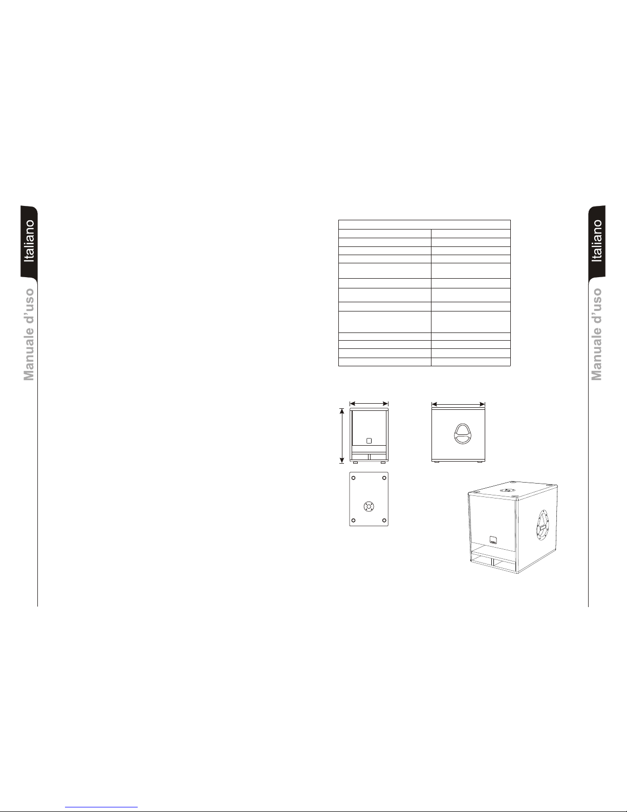
SPECIFICHE TECNICHE
DATI TECNICI
Sistema BAND PASS attivo
Tipologia amplificatore classe H
Potenza RMS 400W
Risposta in frequenza 30-150Hz (± 3dB)
Crossover
Pressione sonora (SPL) 129 peak
Componenti 1 woofer 15”
Sensibilità ingresso 0 dBu (max)
Impedenza ingresso
20Kohm
Forma diffusore rettangolare
Dimensioni [LxHxP] 430x550x600mm
Peso 27Kg
100Hz
24dB/oct
2,5” coil
Bilanciato
Sbilanciato 10Kohm
Alimentazione vedi targa sull’amplificatore
DIMENSIONI
430mm
550mm
600mm
Page 4
5
EnglishEnglishEnglish
user manualuser manual
EnglishEnglishEnglish
user manualuser manual
6
IMPORTANT SAFETY INSTRUCTIONS
CAUTION: TO REDUCE THE RISK OF
ELECTRICAL SHOCK, DO NOT
REMOVE THECOVER (OR BACK). NO
USER SERVICEABLE PARTS INSIDE;
REFER SERVICING TO QUALIFIED
PERSONNEL.
WARNING: TO REDUCE THE RISK OF FIRE OR
ELECTRICAL SHOCK. DO NOT
EXPOSE THIS APPLIANCE TO RAIN OR
MOISTURE.
This symbol, wherever it appears, alerts you to the presence of uninsulated
dangerous voltage voltage inside the enclosure - voltage that may be sufficient to
constitute a risk of shock.
This symbol wherever it appears, alerts you to important operating and
maintenance instructions in the accompanying literature. Read the manual.
DETAILED SAFETY INSTRUCTIONS:
Read these instructions:
All the safety and operation instructions should be read before the appliance is operated.
Keep these instructions:
The safety and operating instructions should be retained for future reference.
Heed all Warnings:
All warnings on the appliance and in the operating instructions should be adhered to
Follow all instructions:
All operation and user instructions should be followed
Water and Moisture:
Do not use this apparatus near water (e.g. near a bathtub, washbowl, kitchen sink, laundry tub, in a wet
basement, or near a swimming pool etc.)
Cleaning:
Clean only with a damp cloth. Do not use solvents, alcohol, benzene or volatile substances for cleaning
the exterior parts.
Ventilation
Do not block any of the ventilation openings. Install in accordance with the manufacturers instructions.
The appliance should be situated so that its location or position does not interfere with its proper
ventilation.
Heat:
Do not install the appliance near any heat sources such as radiators, heat registers, stoves, or other
appliance (including amplifiers) that produce heat.
Grounding or Polarization:
Do not defeat the safety purpose of the polarized or grounding/type plug. To prevent the risk of
electrical shock, the metallic parts of the speaker must be earthed. A polarized plug has two blades
with one wider than the other. A grounding type plug has two blades and a third grounding prong. The
wide blade or the third prong are provided for your safety. When the provided plug does not fit into your
outlet, consult an electrician for replacement of the obsolete outlet.
Power Source
The appliance should be connected to a power supply only of the type described in the operating
instructions or as marked on the appliance. In order not to jeopardize the safety of the speaker, it must
only be connected to the mains using the power cable provided.
Power Cord Protection:
Protect the power cord from being walked on or pinched particularly al plugs, convenience
receptacles, and the point where they exit from the apparatus.
Accessories:
Only use attachments/accessories specified by the manufacturer.
Carts and stands:
Use only with a cart, stand, tripod, bracket, or table specified by the manufacturer, or sold with tha
apparatus. When a cart is used, use caution when moving the cart-apparatus combination to avoid
injury from tip-over.
"AVIS"
RISQUE DE CHOC ELECTRIQUE
NE PAS OUVRIR
POUR PREVENIR TOUT RISQUE DE FEU
REPLACER UN FUSIBLE
DE MÊME CARACTERISTIQUES
CET APPAREIL DOIT ÊNTRE RELIÉ A LA TERRE
"CAUTION"
TO PREVENT ELECTRICAL SHOCK
DO NOT REMOVE COVER
TO PREVENT RISK OF FIRE
REPLACE FUSES WITH
SAME TYPE AND RATINGS
THIS APPARATUS MUST BE EARTHED
Non-use Periods:
Object and Liquid Entry
Damage Requiring Service
Servicing:
IMPORTANT NOTES
This manual is to be considered an integral part of the product, and must always accompany the
speaker when it changes ownership as a reference for correct installation and operation as well as for
the safety regulations.
dB Technologies will not assume any responsibility for incorrect installation of the speaker.
OPERATING PRECAUTIONS
- Do not force the amplifier incorporated in the speaker to work in overload for extended periods
of time.
- Never force the control elements (switches, controls, etc.).
CAUTION
- Make sure that the speaker is positioned in a stable and secure way in order to avoid any
dangerous conditions for persons or objects.
CONNECTION
- For connecting the speaker, use only qualified and experienced personnel having sufficient
technical knowledge or specific instructions for making the connections correctly and thus
preventing electrical dangers.
- To prevent the risk of electrical shock, the speaker must only be supplied from the mains after all
connections have been completed.
- Before powering up the speaker, it is advisable to re-check all the connections, making sure in
particular that there are no short circuits.
- The entire sound system must be designed and installed in compliance with the current
standards and regulations regarding electrical systems.
CAUTION
- To prevent inductive phenomena from giving rise to hum or disturbance which would jeopardize
efficient seaker operation, the cables that transmit microphone signals or line level signals
(e.g. 0 dB/V) must be screened and should not be run in the vicinity of:
1) Equipment that produces strong magnetic fields (e.g. large power supply transformers)
2) Electrical energy conductors
3) Lines that supply speakers.
Unplug this apparatus during lightning storms or when unused for long periods of time.
Care should be taken so that objects do not fall and liquids are not spilled into the enclosure through
openings.
Refer all servicing to qualified service personnel. Servicing is required when:
- the apparatus has been damaged in any way;
- the power supply cord or the plug has been damaged;
- Objects have fallen, or liquid had been spilled into the appliance;
- The appliance has been exposed to rain or moisture;
- The appliance does not appear to operate normally or exhibits a marked change in
performance;
- The appliance had been dropped.
The user should not attempt to service the appliance beyond that is described in the Operating
Instructions. All other servicing should be referred to qualified service personnel.
CAUTION
Page 5

7
EnglishEnglishEnglish
user manualuser manual
EnglishEnglishEnglish
user manualuser manual
8
DESCRIPTION
The SUB 05 speaker features an 15" woofer with an amplifier able to deliver 400W (RMS).
The subwoofer speaker is made using “BAND PASS” so high sound pressures can be
achieved in compact dimensions. Being made of poplar wood, weight is reduced and
handling is easier.
The SUB 05 diffuser has been designed to function in stereo and in mono modes.
This sub-woofer is ideal for sounding medium-sized rooms using a pair of diffusers from the
BASIC 100 or TWIN 128 connected in stereo mode
For installations requiring greater sound pressure, such as those in the open-air, two SUB
05 diffusers should be used together with two BASIC 200, OPERA LIVE 210, TWIN 228 or
OPERA LIVE 202 / OPERA LIVE 205 diffusers connected in mono mode.
COMMANDS AND FUNCTIONS
1) VOLUME CONTROL
The knob regulates the speaker's volume. This control does not affect the
“BALANCED INPUT LINK” and “BALANCED X-OVER OUTPUT” levels.
2) “PROT - LIM” INDICATOR
The “PROT - LIM” indicator lights up red :
- when the amplifier is started (for a few seconds)
- whenever an operating temperature is reached that is too high
- during internal limiter operation, which prevents amplifier distortion and
protects the loudspeakers against overloads.
3) “ON - READY” INDICATOR
The “ON - READY” indicator lights up green when the amplifier is correctly powered
and operating.
4) “PHASE IN - PHASE OUT” SWITCH
This two-position switch permits rotating the audio signal reproduced by the subwoofer by 180°.
Such phase rotation facilitates the optimisation of the reproduction of low
frequencies even in the most difficult installation situations.
After completing installation, play a piece of music and operate the switch to achieve
the best sound reproduction.
5) “BALANCED INPUT ” INPUT CONNECTOR (CH1-CH2)
Balanced input suitable for connecting an audio source with signal output (0dBu).
6) “BALANCED INPUT LINK” OUTPUT CONNECTOR (CH1-CH2)
The output is connected in parallel with the input (5) and can be used for sending the
input audio signal to another amplified diffuser, recorder or supplementary amplifier.
It can hold 3-pin XLR sockets.
7) “BALANCED X-OVER OUTPUT” OUTPUT CONNECTOR (CH1-CH2)
Balanced output of the internal crossover. This signal is sent to an amplified speaker.
The crossover frequency between the subwoofer and the speaker connected to the
X-OVER output is 100Hz.
8) POWER SWITCH
This switch turns the diffuser on and off.
9) POWER CABLE SOCKET
Used for connecting the power cable supplied.
10) FUSE CARRIER
Mains fuse housing.
11) VOLTAGE CHANGE
For changing the power voltage of the speaker (230/115V).
This switch is preset and protected by manufactured
TECHNICAL SPECIFICATION
TECHNICAL DETAIL
System BAND PASS Active
Type of amplifier class H
RMS power 400W
Frequency response 30-150Hz (± 3dB)
Crossover
Sound pressure (SPL) 129 peak
Component parts 1 woofer 15”
Input sensitivity 0 dBu (max)
Impedance input
Balanced 20Kohm
Unbalanced
Speaker shape rectangular
Dimension [LxHxP] 430x550x600mm
Weight 27Kg
100Hz
24dB/oct
2,5” coil
10Kohm
Power supply As indicated on rear panel
DIMENSION
BB
dd
I
E
O
G
C
T
H
O
N
E
S
L
B
B
d
d
B
B
d
d
430mm
550mm
600mm
Page 6

DeutschDeutschDeutsch
BedienungsanleitungBedienungsanleitung
Español
DeutschDeutschDeutsch
BedienungsanleitungBedienungsanleitung
9
10
SICHERHEITSHINWEISE
Dieses Zeichen soll den Benutzer vor Gefahren durch die elektrische Spannung im
Gerät warnen. Diese elektrische Spannung ist so hoch, dass Stromschlaggefahr
besteht.
Dieses Symbol soll den Benutzer auf wichtige Bedienungs- und
Wartungsanweisungen (Kundendienst) in der dem Gerät beiliegenden
Dokumentation hinweisen.
Verdecken Sie keine der Lüftungsöffnungen. Installieren Sie dieses Gerät nach den Anweisungen des
Herstellers.
Installieren Sie es nicht in der Nähe von Wärmequellen wie Heizkörpern, Öfen oder sonstigen Geräten
(einschließlich Verstärker), die Wärme erzeugen.
Beeinträchtigen Sie nicht die Polung und die Erdung des Steckers. Zur Vermeidung von elektrischen
Schlägen müssen die metallischen Teile der Lautsprecherbox geerdet werden. Ein gepolter Stecker
hat zwei Pole, von denen einer breiter ist als der andere. Ein geerdeter Stecker hat zusätzlich zu seinen
beiden Polen einen dritten Pol für die Erdung. Der breitere oder der dritte Pol dient Ihrer Sicherheit.
Wenn sich der Stecker nicht in Ihre Netzsteckdose stecken lässt, wenden Sie sich bitte an einen
Elektriker für den Austausch der veralteten Steckdose.
Um die Sicherheit der Lautsprecherbox nicht zu
beeinträchtigen, darf sie ausschließlich mit dem mitgelieferten Netzkabel an das Netz angeschlossen
werden.
Schützen Sie das Netzkabel vor allem in der Nähe des Steckers und des Anschlusses am Gerät gegen
Beschädigung durch Quetschen oder Zugbelastung.
Verwenden Sie nur das vom Hersteller angegebene Zubehör.
Verwenden Sie nur Wagen, Untergestelle, Stative, Bügel und Halterungen, die vom Hersteller
empfohlen oder mit dem Gerät geliefert werden. Beim Verfahren des Geräts auf einem Wagen darauf
achten, dass es nicht zu Unfällen kommt, weil das Gerät umkippt.
WARNUNG: UM STROMSCHLAGGEFAHR ZU
VERMEIDEN, DEN DECKEL (UND DIE
RÜCKPLATTE) NICHT ENTFERNEN.
DAS GERÄT ENTHÄLT KEINE TEILE,
DIE DER BENUTZER REPARIEREN
DARF. REPARATUREN STETS VOM
FACHMANN AUSFÜHREN LASSEN.
ACHTUNG: UM BRAND- UND
STROMSCHLAGGEFAHR ZU
VERMEIDEN, DAS GERÄT VOR REGEN
UND FEUCHTIGKEIT SCHÜTZEN.
DETAILLIERTE SICHERHEITSHINWEISE:
Lesen Sie diese Anweisungen:
Alle Sicherheitshinweise und Bedienungsanweisungen müssen vor dem Einschalten des Geräts
gelesen werden.
Bewahren Sie diese Anweisungen auf.
Die Sicherheitshinweise und Bedienungsanweisungen müssen sorgfältig aufbewahrt werden, damit
sie auch später zu Rate gezogen werden können.
Baechten Sie alle Warnhinweise.
Alle Warnungen und Bedienungsanweisungen müssen strikt beachtet werden.
Befolgen Sie alle Anweisungen.
Alle Bedienungsanweisungen müssen befolgt werden.
Wasser und Feuchtigkeit
Verwenden Sie dieses von Wasser (z.B. Badewanne, Waschbecken, Spüle,
nasse Böden, in der Nähe von Schwimmbecken usw.) .
Lüftung
Das Gerät muss so aufgestellt werden, dass seine ausreichende Lüftung gewährleistet ist.
Wärme
Stromversorgung
Das Gerät darf nur an die in der Bedienungsanleitung und auf dem Gerät selbst angegebene
Stromversorgung angeschlossen werden.
Netzkabel
Gerät nicht in der Nähe
Reinigung
Reinigen Sie as nur mit einem feuchten Tuch. Für die Außenreinigung des Geräts weder Verdünner,
Alkohol, Benzin noch sonstige flüchtige Substanzen verwenden.
Erdung und Polarität
Zusatzgeräte
Transportmittel und Stative
Bei längerer Nichtverwendung
Bei Gewitter oder bei längerer Nichtverwendung das Gerät von der Netzsteckdose trennen.
Wenden Sie sich für jegliche Reparatur an einen Fachmann. Ein technischer Eingriff ist erforderlich,
wenn
- Das Gerät beschädigt wurde;
WICHTIG
Das vorliegende Handbuch stellt einen integralen Bestandteil des Produktes dar und muss dasselbe
bei einem Wech-sel des Eigentümers begleiten, damit der neue Eigentümer sich über die Art und
Weise der Installation und Benutzung sowie über die Sicherheitshinweise informieren kann.
Bei einer fehlerhaften Installation der Lautsprecherbox lehnt dB Technologies jegliche Haftung ab.
VORSICHTSMASSNAHMEN BEI DER BENUTZUNG
- Vermeiden Sie es, den internen Verstärker der Lautsprecherbox über einen längeren Zeitraum
im Überlastbetrieb einzusetzen.
- Bewegen Sie die Bedienungselemente (Tasten, Regler usw.) nicht mit Gewalt.
ACHTUNG
- Stellen Sie die Lautsprecherbox stabil und sicher auf, so dass Gefahren für Personen oder
Gegenstände unter allen Umständen vermieden werden.
ACHTUNG
- Es wird empfohlen, sich für den Anschluss der Lautsprecherbox an qualifiziertes und
ausgebildetes Personal zu wenden oder aber an Personal, das über eine ausreichende
technische Ausbildung und über die entsprechenden Kenntnisse verfügt, um die Anschlüsse
korrekt auszuführen und die aus der elektrischen Energie hervorgehenden Gefahren zu
vermeiden.
- Zur Vermeidung der Gefahr von elektrischen Schlägen dürfen die Lautsprecher erst nach der
Ausführung sämtlicher Anschlussarbeiten an die Netzspannung angeschlossen werden.
- Vor dem Anlegen der Netzspannung sollten sämtliche Anschlüsse nochmals kontrolliert
werden und insbesondere muss sichergestellt werden, dass keine versehentlichen
Kurzschlüsse vorhanden sind
- Die gesamte Beschallungsanlage muss in Übereinstimmung mit den geltenden
Normbestimmungen und Gesetzen für elektrische Anlagen ausgeführt werden.
HINWEIS
- Zur Vermeidung von Induktionsphänomenen, die zu Brummen und Störungen führen und den
ordnungsgemäßen Betrieb der Lautsprecherbox stören, müssen die Kabel, die die
Mikrofonsignale oder Signale mit Leitungspegel über-tragen (zum Beispiel 0 dB/V)
abgeschirmt sein und sie dürfen nicht verlegt werden in der Nähe von:
! Geräten, die starke Magnetfelder erzeugen (zum Beispiel Leistungstransformatoren);
! elektrischen Leistungskabeln;
! Leitungen, die Lautsprecher speisen.
Eindringen von Fremdkörpern oder Flüssigkeiten in das Gerät
Sicherstellen, dass das Gerät vor herabfallenden Gegenständen und vor herabtropfenden
Flüssigkeiten geschützt ist.
Schäden, die den Kundendienst erfordern
- Netzkabel oder Netzstecker beschädigt.
- Ein Fremdkörper oder Flüssigkeit ist in das Innere des Geräts gelangt.
- Das Gerät war dem Regen ausgesetzt.
- Das Gerät scheint nicht mehr richtig zu funktionieren oder bringt nicht mehr die ursprünglichen
Leistungen.
- Das Gerät ist heruntergefallen oder sonst wie beschädigt.
Wartung
Der Benutzer darf nicht versuchen, am Gerät irgendwelche Reparaturen vorzunehmen, die über das
hinausgehen, was in der Anleitung beschrieben ist. Alle anderen Reparaturen müssen vom Fachmann
ausgeführt werden.
ANSCHLÜSSE
"AVIS"
RISQUE DE CHOC ELECTRIQUE
NE PAS OUVRIR
POUR PREVENIR TOUT RISQUE DE FEU
REPLACER UN FUSIBLE
DE MÊME CARACTERISTIQUES
CET APPAREIL DOIT ÊNTRE RELIÉ A LA TERRE
"CAUTION"
TO PREVENT ELECTRICAL SHOCK
DO NOT REMOVE COVER
TO PREVENT RISK OF FIRE
REPLACE FUSES WITH
SAME TYPE AND RATINGS
THIS APPARATUS MUST BE EARTHED
Page 7

DeutschDeutschDeutsch
BedienungsanleitungBedienungsanleitung
Español
DeutschDeutschDeutsch
BedienungsanleitungBedienungsanleitung
11
12
BESCHREIBUNG
Der Lautsprecher SUB 05 verfügt über einen 15"-Woofer mit einer Endstufe mit
400W/RMS Leistung.
Als Bandpass-Subwoofer bietet der SUB 05 trotz seiner geringen Abmessungen einen
beachtlich hohen Schalldruck. Sein Gehäuse aus Pappelholz zeichnet sich durch sein
geringes Gewicht und die große Handlichkeit aus.
Der Lautsprecher SUB 05 ist ein aktiver, für den Stereobetrieb oder Monobetrieb
konzipierter Subwoofer.
Dieser Subwoofer eignet sich in Kombination im Stereoanschluss mit einem
Lautsprecherpaar der BASIC 100 oder TWIN 128 insbesondere für Räume mit mittleren
Abmessungen oder Für Installationen die einen größeren Schalldruck erfordern, wie für
Anlagen im Freien, zwei Lautsprecher der SUB 05 in Kombination mit Lautsprechern
BASIC 200, OPERA LIVE 210, TWIN 228 oder OPERA LIVE 202 / OPERA LIVE 205 im
Monoanschluss.
TECHNISCHE EIGENSCHAFTEN
TECHNISCHE DATEN
System BAND PASS Aktiv
Versterker typ klass H
RMS leistung 400W
requengang +/-3dB 30-150Hz (± 3dB)
Crossover
Schalldruck (SPL) 129 peak
Lautsprecher 1 woofer 15”
Empfindlichkeit eingang 0 dBu (max)
Impedanz eingang
Simmetrisch 20Kohm
Ünsimmetrisch
Netzspannung Wie au der rückwand angegeben
Laufsprecherform rechteckig
Abmessungen [LxHxP] 430x550x600mm
Gewichtt 27Kg
F
100Hz
24dB/oct
2,5” coil
10Kohm
ABMESSUNGEN
RUNGEN UND FUNKTIONEN
1) BEDIENUNGSELEMENT VOLUME
Der Drehknopf regelt die Lautstärke des Lautsprechers.
Diese Einstellung hat keinerlei Wirkung auf den Ausgang “BALANCED INPUT
LINK“ und “BALANCED X-OVER OUTPUT“.
2) KONTROLLLAMPE ”PROT - LIM”
Die Kontrolllampe ”PROT - LIM” leuchtet rot:
- beim Einschalten des Verstärkers (für einige Sekunden)
- bei zu hoher Betriebstemperatur
- bei Ansprechen des internen Limiters, der Verzerrungen verhindert und
die Lautsprecher vor Beschädigungen schützt.
3) KONTROLLLAMPE ”ON - READY”
Die Kontrolllampe ”ON - READY” leuchtet grün, wenn die Netzspannung
vorhanden ist und der Verstärker ordnungsgemäß funktioniert.
4) WAHLSCHALTER ”PHASE IN - PHASE OUT”
Mit diesem Wahlschalter mit zwei Schaltstellungen kann man die Phase des
Subwoofers um 180° drehen.
Durch das Drehen der Phase kann man die Wiedergabe der Bässe auch bei
ungünstigen akustischen Bedingungen in einfacher Weise optimieren.
Nach Abschluss der Installation ein Musikstück abspielen und ausprobieren, in
welcher Schaltstellung des Phasenschalters der Klang am besten ist
5) EINGANG “BALANCED INPUT” ( CH1 und CH2)
Symmetrischer Eingang für den Anschluss einer Tonquelle mit einwandfreiem
Signalausgang (0dBu).
6) AUSGANG “BALANCED INPUT LINK” (CH1 und CH2)
Der Ausgang ist parallel mit dem Eingang (5) angeschlossen. Über diesen Ausgang
können eingehende Tonsignale an einen anderen verstärkten Lautsprecher, einen
Recorder oder Zusatzverstärker weitergeleitet werden. Er eignet sich zur
Aufnahme von 3-poligen XLR-Steckern.
7) AUSGANG “BALANCED X-OVER OUTPUT” (CH1 und CH2)
Symmetrischer Ausgang der internen Frequenzweiche. Dieses Signal kann z.B.
an einen aktiven Lautsprecher, angeschlossen zur Mittel-Hochton-Wiedergabe
angeschlossen werden. Die Trennfrequenz zwischen dem Subwoofer und dem an
den Ausgang X-OVER angeschlossenen Lautsprecher ist 100Hz.
8) NETZSCHALTER “POWER”
Dieser Schalter dient zum EIN- und AUS-Schalten der Lautsprecherbox.
9) ANSCHLUSS NETZKABEL
Netzanschluss zur Aufnahme des mitgeliferten Stromkabel.
10) "FUSE" SICHERUNGSHALTER
Integrierte Netzsicherung. Bei Defekt nur durch eine identische Sicherung
ersetzen!
11) SPANNUNGSWECHSEL
Zur Änderung der Leistungsspannung des Diffusors (230/115V WS).
Dieser Wahlschalter wird von der Herstellerfirma vorjustiert und geschützt.
BB
d d
H
L
G
S
E
O
O
E
C
I
TN
BB
dd
BB
dd
430mm
550mm
600mm
Page 8

Caracteristiques techniquesCaracteristiques techniques
FrançaisFrançais
14
FrançaisFrançais
Caracteristiques techniquesCaracteristiques techniques
13
INSTRUCTIONS DE SÉCURITÉ
AVERTISSEMENTS: AFIN DE LIMITER LES RISQUES DE
DÉCHARGE ÉLECTRIQUE, NE PAS
ENLEVER LE COUVERCLE (OU LE
PANNEAU ARRIÈRE). LES COMPOSANTS
INTERNES NE PEUVENT PAS ÊTRE
RÉPARÉS PAR L'UTILISATEUR; CONFIER
LES RÉPARATIONS À DU PERSONNEL
QUALIFIÉ.
ATTENTION: AFIN DE RÉDUIRE LES RISQUES
D'INCENDIE OU DE DÉCHARGE
ÉLECTRIQUE, NE PAS EXPOSER CET
APPAREIL À LA PLUIE OU À L'HUMIDITÉ.
Ce symbole a la fonction de signaler à l'utilisateur, là où il est apposé, la présence de tension
dangereuse à l'intérieur du produit, avec une valeur suffisante pour représenter un risque de
décharge électrique pour les personnes.
Ce symbole, là où il est reporté, a la fonction de signaler à l'utilisateur la présence d'instructions
d'utilisation et entretien (assistance) importantes dans la documentation qui accompagne
l'appareil.
INSTRUCTIONS DE SÉCURITÉ DÉTAILLÉES:
Avant de mettre en fonction l'appareil, lire toutes les instructions de sécurité et de fonctionnement.
Conserver ces instructions
Les instructions de sécurité et de fonctionnement doivent être conservées pour toute éventuelle
consultation future.
Respecter scrupuleusement tous les avertissements présents sur l'appareil et les instructions de
fonctionnement.
Toutes les instructions de fonctionnement et pour l'utilisateur doivent être respectées.
Eau et humidité
(par exemple à proximité de baignoires, lavabos, éviers,
lavoirs, sur le sol mouillé ou à proximité de piscines…)
Nettoyage
Pour le nettoyange des parties extérieures, évitez les
diluants, l’alcool, l’essence ou autres substances volatiles.
Ventilation
Ne jamais placer l’appareil dans un endroit qui risque d’empêcher une bonne
ventilation.
Chaleur
Mise à la terre et polarités
Alimentation
L'appareil ne doit être branché qu'au type d'alimentation indiqué dans les instructions d'utilisation ou
reporté sur l'appareil.
Cordon d'alimentation
Accessoires
Chariots et support
Lire les instructions suivantes.
Tenir compte de tous les avertissements.
Suivre toutes les instructions
Ne pas utiliser cet appareil à proximité de l'eau
Nettoyer exclusivement avec un chiffon humide.
Ne pas boucher les fentes de ventilation. Installer cet appareil conformément aux instructions fournies
par le fabricant.
Installer l'appareil à l'écart des sources de chaleur comme radiateurs, poêles ou tout autre appareil (y
compris les amplificateurs) qui produit de la chaleur.
Ne pas altérer la polarisation ou la mise à la terre de la fiche. Pour éviter le risque de chocs électriques,
les parties métalliques de l’enceinte doivent être reliées à la terre. Une fiche polarisée comporte deux
broches, l'une étant plus large que l'autre. Une fiche munie de mise à la terre comporte deux broches
plus une troisième broche pour la mise à la terre. La broche plus large ou la troisième broche sont
prévues pour assurer la sécurité. Si l'on n'arrive pas à brancher la fiche dans la prise de réseau,
contacter un électricien pour faire remplacer la prise obsolète.
Pour ne pas compromettre la sécurité de l’enceinte, utilisez pour la brancher
exclusivement le câble d’alimentation fourni dans l’emballage.
Protéger le cordon d'alimentation afin d'éviter de marcher dessus ou de le pincer, surtout à proximité de
la fiche et dans le point de connexion à l'appareil.
Utiliser uniquement les accessoires indiqués par le fabricant.
Utiliser uniquement des chariots, supports, pieds, étriers ou fixations conseillés par le fabricant ou
fournis avec l'appareil. Quand on utilise un chariot, déplacer l'appareil avec précaution afin d'éviter des
accidents à cause de renversements.
"AVIS"
RISQUE DE CHOC ELECTRIQUE
NE PAS OUVRIR
POUR PREVENIR TOUT RISQUE DE FEU
REPLACER UN FUSIBLE
DE MÊME CARACTERISTIQUES
CET APPAREIL DOIT ÊNTRE RELIÉ A LA TERRE
"CAUTION"
TO PREVENT ELECTRICAL SHOCK
DO NOT REMOVE COVER
TO PREVENT RISK OF FIRE
REPLACE FUSES WITH
SAME TYPE AND RATINGS
THIS APPARATUS MUST BE EARTHED
Périodes de non-utilisation
Entrée de liquides et d'objets dans l'appareil
Veiller à ce qu'aucun objet ne tombe sur l'appareil et qu'aucun liquide ne passe à travers les
ouvertures.
Dommages nécessitant l'intervention du service d'assistance
- le cordon d'alimentation ou la prise sont endommagés;
- des objets sont tombés sur l'appareil ou des liquides sont entrés dedans;
- l'appareil a été exposé à la pluie;
- l'appareil ne semble pas fonctionner correctement ou ses performances ont changé;
- l'appareil est tombé.
Entretien
L'utilisateur ne doit pas essayer d'effectuer des réparations autres que celles décrites dans les
instructions. Toutes les autres réparations doivent être exécutées par du personnel qualifié.
Débrancher l'appareil de la prise d'alimentation en cas d'orage ou en cas de périodes d'inutilisation
prolongées.
S'adresser à du personnel qualifié pour toute réparation. Une intervention technique s'avère
nécessaire quand
- l'appareil a été endommagé;
MPORTANT
Ce manuel fait partie intégrante du produit et doit suivre celuici même dans les passages de propriété,
pour permettre au nouveau propriétaire de connaître les modalités d’installation et d’utilisation ainsi
que les consignes de sécurité.
Toute mauvaise installation de l’enceinte décharge dB Technologies de toute responsabilité.
PRÉCAUTIONS
- Evitez de faire longtemps travailler en surcharge l’amplificateur à l’intérieur de l’enceinte.
- Ne forcez pas les organes de commandes (touches, contrôles, etc.)
ATTENTION
- Installez l’enceinte de manière stable et sûre pour éviter tout risque de blessures et/ou dégâts.
BRANCHEMENTS
ATTENTION
- Pour brancher l’enceinte, adressez-vous à un spécialiste bien formé, c’est-à-dire à une
personne ayant de l’expérience ou des connaissances techniques ou ayant reçu des
instructions spécifiques qui lui permettent de réaliser correctement les connexions et de
prévenir les dangers de l’électricité.
- Pour éviter les risques de chocs électriques, terminez toutes les connexions avant de brancher
l’enceinte sur le secteur.
- Avant d’alimenter l’enceinte, il est de bonne règle de recontrôler toutes les connexions et de
s’assurer en particulier qu’il n’y a pas de courts-circuits accidentels.
- Tout le système de sonorisation devra être réalisé conformément aux normes et aux lois en
vigueur en matière d’instal-lations électriques.
- Pour éviter que des phénomènes inductifs provoquent des bourdonnements, perturbent et
compromettent le bon fonctionnement de l’enceinte, blindez les fils qui transmettent des
signaux microphoniques ou des signaux au niveau de la ligne (0 dB/V) et évitez de les poser à
proximité de :
! appareils produisant de forts champs magnétiques (gros transformateurs
d’alimentation) ;
! conducteurs de l’énergie électrique.
! lignes qui alimentent les enceintes.
MISE EN GARDE
Page 9
Caracteristiques techniquesCaracteristiques techniques
FrançaisFrançais
16
FrançaisFrançais
Caracteristiques techniquesCaracteristiques techniques
15
DESCRIPTION
L'enceinte SUB 05 est équipée d'un HP grave de 15” avec un amplificateur en mesure de
diffuser 400W (RMS).
L'enceinte SUB 05 est réalisée en utilisant la typologie “ BAND PASS ”, qui permet d'obtenir
des pressions acoustiques élevées avec des dimensions réduites. La fabrication en bois
de peuplier diminue le poids et favorise la maniabilité.
Le diffuseur SUB 05 est un sub-woofer actif conçu pour fonctionner en modalité stéréo ou
en modalité mono.
Ce sub-woofer est idéal pour la sonorisation d'espaces de milieu dimensions associé à une
paire de diffuseurs de la BASIC 100 ou TWIN 128 en modalité stéréo.
Pour les installations nécessitant une pression sonore supérieure, ainsi à ciel ouvert,
utiliser deux diffuseurs SUB 05 associés à deux diffuseurs
et branché en modalité mono.
BASIC 200, OPERA LIVE 210,
TWIN 228 ou OPERA LIVE 202 / OPERA LIVE 205
COMMANDES ET FONCTIONS
1) CONTRÔLE VOLUME
La commande permet de régler le volume du diffuseur. Ce contrôle n'influe pas sur le
niveau de la sortie "BALANCED INPUT LINK" et "BALANCED X-OVER OUTPUT".
2) VOYANT “PROT - LIM”
Le voyant “PROT - LIM” s'allume de couleur rouge quand:
- lors de la mise sous tension de l'amplificateur (pendant quelques secondes)
- en cas de température de fonctionnement trop élevée
- lors de l'intervention du circuit limiteur interne qui évite la distorsion de
l'amplificateur et protège les haut-parleurs contre les surcharges.
3) VOYANT “ON - READY”
Le voyant “ON - READY” s'allume de couleur verte quand l'alimentation est présente
et quand l'amplificateur fonctionne correctement.
4) SÉLECTEUR “PHASE IN - PHASE OUT”
Ce sélecteur à deux positions permet la rotation de 180° du signal audio reproduit par
le caisson de grave.
Cette rotation de phase facilite l'optimisation de la reproduction des basses
fréquences même dans les conditions d'installation les plus difficiles.
Une fois l'installation terminée, reproduire un morceau de musique et agir sur
l'interrupteur afin d'obtenir la meilleure restitution acoustique.
5) CONNECTEUR D'ENTRÉE "BALANCED INPUT” (CH1 ET CH2)
Entrée équilibrée utilisable pour le branchement d'une source audio à sortie de
signal à haut niveau (0 dBu).
6) CONNECTEUR DE SORTIE "BALANCED INPUT LINK" (CH1 ET CH2)
La sortie est reliée en parallèle à l'entrée (5) et peut être utilisée pour transmettre un
signal audio en entrée à un autre diffuseur amplifié, à un enregistreur ou à un
amplificateur supplémentaire. Il prévu pour les prises "XLR" à 3 pôles.
7) CONNECTEUR DE SORTIE "BALANCED X-OVER OUTPUT" (CH1 ET CH2)
Sortie équilibrée du crossover interne. Ce signal doit être transmis à un diffuseur
amplifié. La fréquence de croisement entre le caisson de grave et l'enceinte
connectée à la sortie X-OVER est de 100Hz.
8) INTERRUPTEUR “POWER”
L’interrupteur permet d’allumer et d’éteindre l’enceinte.
9) PLAQUE SPÉCIFICATIONS
Le valeurs de tension/courant nécessaires pour un bon fonctionnement, le code du
produit et le numéro de série sont imprimés sur cette plaque.
10) BLOC À FUSIBLES “FUSE”
Logement pour le fusible de secteur.
11) CHANGEMENT TENSION
Permet de modifier la tension d'alimentation de l'enceinte (230/115Vc.a.).
Ce sélecteur est préréglé et protégé en usine.
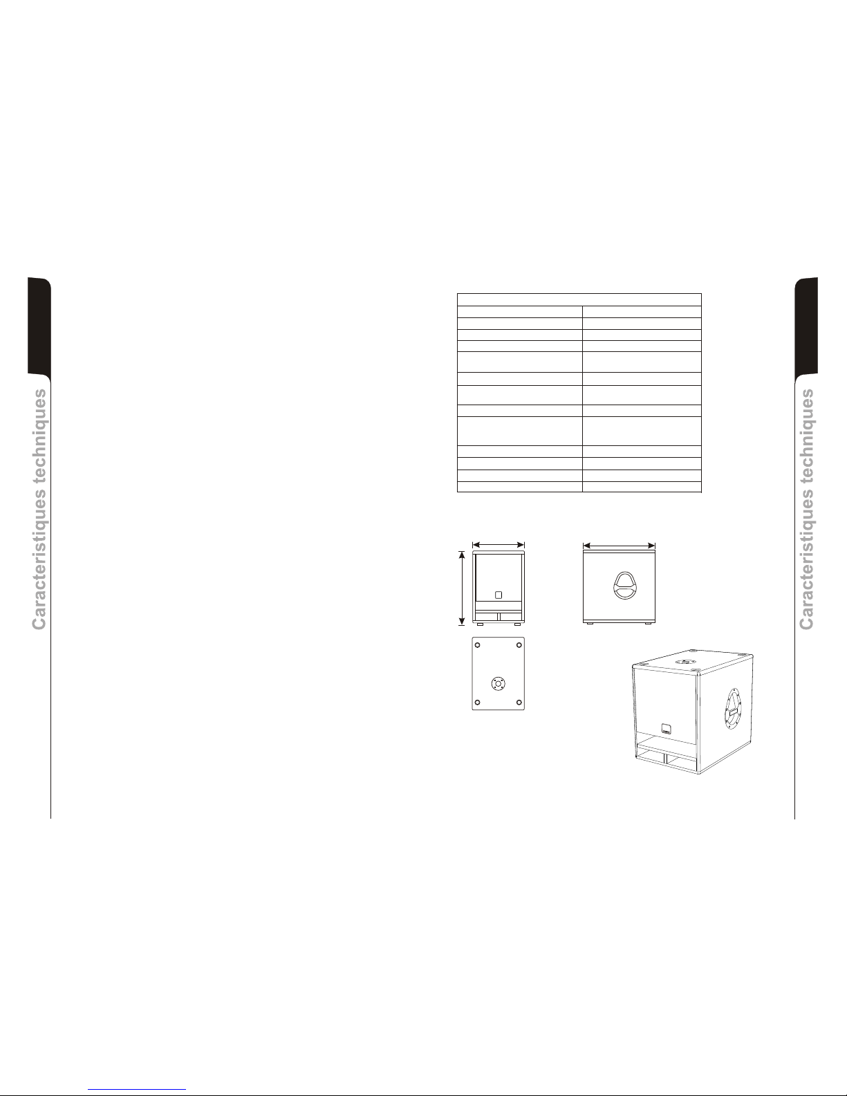
CARACTÉRISTIQUE TECHNIQUES
DIMENSIONS
DONNES TECHNIQUES
Système BAND PASS Active
Typologie amplificateur klass H
Puissance RMS 400W
+/-3dB 30-150Hz (± 3dB)
Crossover
Pression sonore (SPL) 129 peak
Composantes 1 woofer 15”
Entrée sensibilité 0 dBu (max)
Impedance entrée
Symétrique 20Kohm
Asymétrique
Alimentation
Forme enceinte rectangulaire
Dimensions [LxHxP] 430x550x600mm
Poids 27Kg
Réponse en fréquence
Voir plaque
100Hz
24dB/oct
2,5” coil
10Kohm
BB
d d
I
E
O
G
C
T
H
O
N
E
S
L
B
B
d
d
B
B
d
d
430mm
550mm
600mm
Page 10

30Hz HIGH PASS
FILTER
AMP
SUBWOOFER
VOLUME
WOOFER
LIM
THERMAL
CONTROL
BALANCED
INPUT
BALANCED
X-OVER
OUTPUT
STATUS
INDICATORS
"CAUTION"
TO PREVENT ELECTRICAL SHOCK
DO NOT REMOVE COVER
TO PREVENT RISK OF FIRE
REPLACE FUSES WITH
SAME TYPE AND RATINGS
THIS APPARATUS MUST BE EARTHED
"AVIS"
POUR PREVENIR TOUT RISQUE DE CHOC
ELECTRIQUE, NE PAS OUVRIR
POUR PREVENIR TOUT RISQUE DE FEU
REPLACER UN FUSIBLE
DE MÊME CARACTERISTIQUES
CET APPAREIL DOIT ÊNTRE RELIÉ A LA TERRE
BB
dd
TECHNOLOGIESTECHNOLOGIES
Made in italyMade in italy
AC MAINSAC MAINS
POWERPOWERFUSEFUSE
ONON
OFFOFF
ON - READYON - READY
PROT - LIMPROT - LIM
FASE INFASE IN
FASE OUTFASE OUT
BALANCED
INPUT LINK
BALANCED
INPUT LINK
BALANCED
INPUT LINK
BALANCED
INPUT LINK
BALANCED
X-OVER
OUTPUT
BALANCED
X-OVER
OUTPUT
BALANCED
X-OVER
OUTPUT
BALANCED
X-OVER
OUTPUT
BALANCED
INPUT
BALANCED
INPUT
BALANCED
INPUT
BALANCED
INPUT
VOLUMEVOLUME
CH1CH1
CH2CH2
maxmax
230230
1 - GND
2 - HOT
3 - COLD
1 - GND
2 - HOT
3 - COLD
1 - GND
2 - HOT
3 - COLD
1 - GND
2 - HOT
3 - COLD
PUSHPUSH
SUBWOOFERSUBWOOFER
STEREO ACTIVESTEREO ACTIVE
PUSHPUSH
MODEL : SERIAL N.MODEL : SERIAL N.
EARTHEARTH
SUB 05SUB 05
1
2
3
4
5
6
7
8
9
10
11
BALANCED
INPUT LINK
X-OVER
100Hz
BALANCED
INPUT
BALANCED
X-OVER
OUTPUT
BALANCED
INPUT LINK
X-OVER
100Hz
FAN
17
2 X BASIC 200
2 X SUB 05
2 X TWIN 228
2 X SUB 05
2 X OPERA LIVE 210
2 X SUB 05
2 X BASIC 100
1 X SUB 05
2 X TWIN 128
1 X SUB 05
2 X OPERA LIVE 202 /205
2 X SUB 05
18
CONFIGURAZIONI - CONFIGURATIONS
KONFIGURATIONEN - CONFIGURATIONS
SCHEMA A BLOCCHI - BLOCK DIAGRAM
BLOCKSCHALTBILD - SCHEMAS FONCTIONNELS
DIAGRAMA EM BLOQUES
Page 11

ON - READY
PROT - LIM
FASE IN
FASE OUT
BALANCED
INPUT LINK
BALANCED
INPUT LINK
BALANCED
X-OVER
OUTPUT
BALANCED
X-OVER
OUTPUT
BALANCED
INPUT
BALANCED
INPUT
VOLUME
CH1
CH2
max
1 - GND
2 - HOT
3 - COLD
1 - GND
2 - HOT
3 - COLD
PUSH
PUSH
Collegamenti
Cable connections
Verkabelung
Cableado
Cablage
FULL RANGE OUT
FULL RANGE OUT
MIXER
MIXER
STEREO
ON - READY
PROT - LIM
FASE IN
FASE OUT
BALANCED
INPUT LINK
BALANCED
INPUT LINK
BALANCED
X-OVER
OUTPUT
BALANCED
X-OVER
OUTPUT
BALANCED
INPUT
BALANCED
INPUT
VOLUME
CH1
CH2
max
1 - GND
2 - HOT
3 - COLD
1 - GND
2 - HOT
3 - COLD
PUSH
PUSH
FULL RANGE OUT
MIXER
MONO
Collegamenti
Cable connections
Verkabelung
Cableado
Cablage
ON - READY
PROT - LIM
FASE IN
FASE OUT
BALANCED
INPUT LINK
BALANCED
INPUT LINK
BALANCED
X-OVER
OUTPUT
BALANCED
X-OVER
OUTPUT
BALANCED
INPUT
BALANCED
INPUT
VOLUME
CH1
CH2
max
1 - GND
2 - HOT
3 - COLD
1 - GND
2 - HOT
3 - COLD
PUSH
PUSH
LINK
MIXER MIXER
MIXER
ON - READY
PROT - LIM
FASE IN
FASE OUT
BALANCED
INPUT LINK
BALANCED
INPUT LINK
BALANCED
X-OVER
OUTPUT
BALANCED
X-OVER
OUTPUT
BALANCED
INPUT
BALANCED
INPUT
VOLUME
CH1
CH2
max
1 - GND
2 - HOT
3 - COLD
1 - GND
2 - HOT
3 - COLD
PUSH
PUSH
MIXER
MIXER
19
20
ACTIVE SPEAKER
BALANCED
INPUTS / LINK
1 - GND
2 - HOT
3 - COLD
PUSH
ACTIVE SPEAKER
BALANCED
INPUTS / LINK
1 - GND
2 - HOT
3 - COLD
PUSH
SUB 05
ACTIVE SPEAKER
BALANCED
INPUTS / LINK
1 - GND
2 - HOT
3 - COLD
PUSH
ACTIVE SPEAKER
BALANCED
INPUTS / LINK
1 - GND
2 - HOT
3 - COLD
PUSH
ACTIVE SPEAKER
BALANCED
INPUTS / LINK
1 - GND
2 - HOT
3 - COLD
PUSH
SUB 05 SUB 05 SUB 05
 Loading...