

Page 1

Made in Italy
COD. 420120169 Rev 4.0
digital power
RR
ACTIVE SUBWOOFER
22
SS
00
MANUALE d’USO - Sezione 1
USER MANUAL - Section 1
BEDIENUNGSANLEITUNG - Abschnitt 1
CARACTERISTIQUES TECHNIQUES - Section 1
Page 2

3
EnglishEnglishEnglish
user manualuser manual
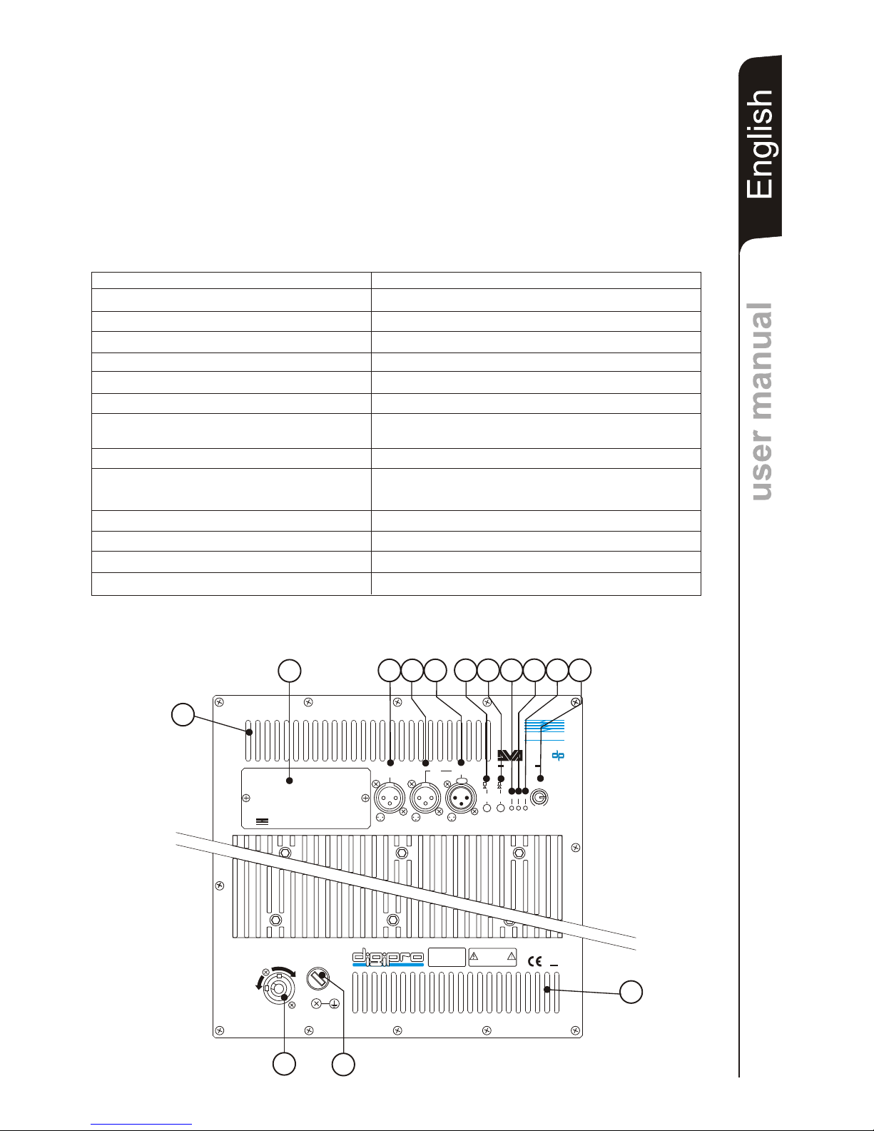
CONTROLS AND FUNCTIONS
1) "MAINS FUSE" FUSE CARRIER
Mains fuse housing.
2) “FULL RANGE MAINS INPUT" POWER SOCKET
For connecting the power cable provided.
The connector used for mains connection is a POWER CON® (blue)
3) COOLING GRILLE
These grilles permit cooling the amplifier during operation.
Do not block accesses and clean the grilles whenever necessary to ensure correct
air circulation.
4) " BALANCED MAIN INPUT” INPUT CONNECTOR
Balanced input at line level (0 dBu).
It is able to accept “XLR” sockets.
5) "LINK” OUTPUT CONNECTOR
The “XLR” connector connected in parallel with input (4) can be used to send the
input audio signal to another amplified speaker.
6) ”BALANCED X-OVER OUTPUT” OUTPUT CONNECTOR
Internal crossover balanced output. The signal from this output can be sent to any
other amplified speaker.
The crossover frequency can be selected by means of the “SUB X-OVER” switch
(7).
7) “SUB X-OVER” SWITCH
This switch permits selection of crossover frequency between the sub woofer and
the speakers connected to the ”BALANCED X-OVER OUTPUT” connector.
The crossing frequency is selected to 90Hz or 120Hz with a slope of 24dB/oct.
The frequency choice depends to the sound reproduction desire.
8) “SUB PHASE ” SWITCH
This switch permits 180° rotation of the audio signal reproduced by subwoofer.
Rotation makes for easier optimization of low-frequency reproduction even in the
most difficult installation situations. After completing installation, reproduce a piece
of music and adjust the switch to obtain the best low-frequency sound.
9) “ON” INDICATOR LIGHT
The “ON” indicator light comes on green to indicate the amplifier is switched on and it
is working properly.
10) “SGN” INDICATOR LIGHT
This indicator comes on green to indicate the presence of the audio signal (at a level
of -20dB).
11) “LIM” INDICATOR LIGHT
This indicator comes on red to indicate that the internal limiter circuit has tripped.
This prevents amplifier distortion and protects the speakers against overloads.
It is lights for a few seconds during the switching on.
12) “SUB WOOFER LEVEL” INPUT SENSITIVITY CONTROL
This control regulates the sensitivity of the signal at amplifier input.
This control does not affect the “LINK” and “BALANCED X-OVER OUTPUT” output
levels
13) DIGITAL DELAY “SDD - SUBWOOFER DIGITAL DELAY” OPTION
The DVA loudspeaker can be equipped with a delay module (SDD SUBWOOFER DIGITAL DELAY) that allows to delay the sound signal reproduced
by the subwoofer.
S20dp
This circuit allows sound-alignment between line array and sub
by balancing the various positions.
The circuit also includes a balanced “XLR” output that sends the delayed audio
signal to other subwoofers. By using a single delay module it is possible to delay
several subwoofers at the same time.
This module can also be used to create cardioid configuration systems. The cardioid
configuration provides a remarkable attenuation of the low frequencies radiated by
TECHNICAL SPECIFICATION
EMI CLASSIFICATION
According to the standards EN 55103 this equipment is designed and suitable to operate in
E5 Electromagnetic environment.
Page 3
EnglishEnglishEnglish
user manualuser manual
4
TECHNICAL SPECIFICATION
System Active
Type of amplifier Digital - Class D (DIGIPRO )
RMS power 2000 W (1000 W + 1000 W)
Musical power 4000 W
Frequency responce +/-3dB
Sound pressure (SPL) 138dB peak
Woofer 2 x woofer 18”- 4” voice coil
Neodymium or Ceramic
Input sensitivity nominal 0 dBu
Impedance input Balanced 20Kohm
Unbalanced 10Kohm
Speaker shape rectangular
Dimension [WxHxD] 1100x720x580mm
Weight Neodymium 77Kg - Ceramic 84Kg
®
25-150Hz
Crossover 90 - 120Hz (24dB/oct) selecting
Full-range with PFC, 100-240Vac, 50-60HzPower supply
the rear side of the subs, without changing the direct radiated signal on the front
side.
This configuration needs at least 3 subwoofers (two with front radiation and one with
rear radiation equipped with SDD module). See appendix for more details.
1
2
3
3
SUBWOOFER DIGITAL DELAY
DD
B
d
TECHNOLOGIESTECHNOLOGIES
SS
OPTIONAL CARD
DD
13
BALANCED
X-OVER
OUTPUT
1
2
3
5
6
O
N
F
F
O
MAINS FUSE
FULL RANGE MAINS INPUT
100-240V~ 50-60Hz
2500W MAX
220-240V~ (T10A 250V)
100-120V~ (T20A 250V)
ACTIVE P.F.C.
BB
dd
TECHNOLOGIESTECHNOLOGIES
SERIAL N.
“CAUTION”
TO PREVENT ELECTRICAL SHOCK
DO NOT REMOVE COVER
“AVIS”
RISQUE DE CHOCH ELECTRIQUE
NE PAS OUVRIR
22
SS
00
BALANCED
MAIN INPUT
LINK
+10
+4
SUB-WOOFER
LEVEL
90Hz
120Hz
0°
180°
ON SGN
LIM
SUB
PHASE
SUB
XOVER
1
2
3
1 = GND
2 = HOT
3 = COLD
12
3
8
0dB
PUSH
4
8
101211
9
7
digital power
EMI CLASSIFICATION
According to the standards EN 55103 this equipment is designed and suitable to operate in
E5 Electromagnetic environment.
NEODYMIUM CERAMIC
Page 4

9
SCHEMA A BLOCCHI
BLOCK DIAGRAM
BLOCKSCHALTBILD
DIAGRAMA EM BLOQURES
B
A
A
CEL N
D
M
A N
NP
TI I U
LN
KI
B
A A
NC
DL E
X-
V
R
O
E
U
PU
TO
T
0H
z9
20
z 1 H
S
U
B
X
V
EO
R
s it
c
w
h
D
g
t
al
ea
i i D
l
y
O
p i
on
l
t
a
W OF R
1
”
O E
8
L
MITERI
S
BU
PH SEA
s
w
i cht
h
s
e
P a
10°8
P
h se
a
0°
S
G
N
AI L
-
2
0 Bd
CO
TRO
L
CU
I
TN
C
I
R
S
L
N
IN
I
P
UM
A
S N T
I
N
MA S
FS
E
U
N
P
T
I U
S
NS
E
EA Y
R
D
Swcin
Mo
de
it
h
g
P
ow r
S
up
p
l
ye
PFC
P
w
er F
coro
a t
Corr c i
o
e t n
PSSM
C
a
s D
l s
®
DI
G
I
P
RO
l s
s D
C a
WOO E
1
8
F R ”
Sw
itc
hi g
M dn
oe
Pwe
r
S pl
yo
u
p
PF
C
P
ow
e F
a
c
to
r r
C r
r
e
c
tiono
SMP
S
C
l ss
Da
®
G
R
DIIPO
Ca s l
s
D
Page 5

10
COLLEGAMENTI
CABLE CONNECTIONS
VERKABELUNG
CABLAGE
BALANCED
MAIN INPUT
LINK
BALANCED
X-OVER
OUTPUT
1
2
3
1 = GND
2 = HOT
3 = COLD
1
2
3
1
2
3
PUSHPUSH
BALANCED
INPUT
BALANCED
LINK / OUT
1 = GND
2 = HOT
3 = COLD
PUSH
Digital Vertical Array
T
4
MIXER
FULL RANGE
OUTPUT
BALANCED
INPUT
BALANCED
LINK / OUT
1 = GND
2 = HOT
3 = COLD
PUSH
Digital Vertical Array
T
4
BALANCED
INPUT
BALANCED
LINK / OUT
1 = GND
2 = HOT
3 = COLD
PUSH
Digital Vertical Array
T
4
BALANCED
INPUT
BALANCED
LINK / OUT
1 = GND
2 = HOT
3 = COLD
PUSH
Digital Vertical Array
T
4
22
SS
00
Page 6

11
INSTALLAZIONE
INSTALLATION
INSTALLATIONEN
INSTALLATIONS
Utilizzo in appoggio
Supported use
Anwendung mit Aufstützung
Utilisation en appui
Impilato
Stacked
Aufgesetzt
Empilée
Page 7

12
Utilizzo in appoggio verticale (DVA T4 montaggio “Ground stacking”)
Supported use (DVA T4 ““Ground stacking” assembling)
Anwendung mit Aufst DVA T4 ““Ground stacking”
DVA T4 ““Ground stacking” installation)
ützung ( Zusammenbauen)
Utilisation en appui (
Page 8

13
Per supporto asta
Stand adaptor
Opzione DSA 4
DSA 4 Option
Per supporto asta
Stand adaptor
In appoggio
Floor stack
Page 9

14
In appoggio
Floor stack
Set di 4 ruote - opzione DWK 20
Set of 4 wheels - DWK 20 option
Page 10

15
Digital Delay subwoofer - opzione SDD
Subwoofer Digital Delay - SDD option
GAP
ALLINEAMENTO SEGNALE AUDIO
ALIGNAMENT AUDIO SIGNAL
CONFIGURAZIONE CARDIOIDE
Delay setup = (GAP X 1000) / 344
Delay = ms (specify milliseconds)
GAP = m (specify meters)
Sound speed = 344 m/s
Ruotare la fase di 180°
Rotate 180° phase
Impostare il delay a 4,5msec
Set delay to 4,5msec
mSec
DELAY SET-UP
.0
.5
.4
.3
.1
.2
.6
.7
.8
.9
0
5
4
3
1
2
6
7
8
9
0
50
40
30
10
20
60
70
80
90
- - -
.
Delay = ms (espresso in millisecondi)
GAP = m (espresso in metri)
Velocità suono = 344 m/s
SUBWOOFER DIGITAL DELAYSUBWOOFER DIGITAL DELAY
DD
BB
dd
TECHNOLOGIESTECHNOLOGIES
SS
OPTIONAL CARDOPTIONAL CARD
DD
BALANCED
X-OVER
OUTPUT
BALANCED
X-OVER
OUTPUT
11
22
33
BB
dd
TECHNOLOGIESTECHNOLOGIES
22
SS
00
BALANCED
MAIN INPUT
BALANCED
MAIN INPUT
LINKLINK
+10+10
+4+4
SUB-WOOFER
LEVEL
SUB-WOOFER
LEVEL
90Hz90Hz
120Hz120Hz
0°0°
180°180°
ONON SGNSGN
LIMLIM
SUB
PHASE
SUB
PHASE
SUB
XOVER
SUB
XOVER
11
22
33
1 = GND
2 = HOT
3 = COLD
1 = GND
2 = HOT
3 = COLD
1122
33
88
0dB0dB
PUSHPUSH
ISTRUZIONI DI SICUREZZA PER ACCESSORI /
ZUBEHÖR NSTRUCTIONS DE SÉCURITÉ
Page 11

mSec
DELAY SET-UP
.0
.5
.4
.3
.1
.2
.6
.7
.8
.9
0
5
4
3
1
2
6
7
8
9
0
50
40
30
10
20
60
70
80
90
- - -
.
CONFIGURAZIONE CARDIOIDE
CARDIOID CONFIGURATION
16
PUSH
Ruotare la fase di 180°
Rotate 180° phase
SUB
PHASE
0°
180°
Impostare il delay a 4,5msec
Set delay to 4,5msec
BALANCED
X-OVER
OUTPUT
BALANCED
X-OVER
OUTPUT
11
22
33
BB
dd
TECHNOLOGIESTECHNOLOGIES
22
SS
00
BALANCED
MAIN INPUT
BALANCED
MAIN INPUT
LINKLINK
+10+10
+4+4
SUB-WOOFER
LEVEL
SUB-WOOFER
LEVEL
90Hz90Hz
120Hz120Hz
0°0°
180°180°
ONON SGNSGN
LIMLIM
SUB
PHASE
SUB
PHASE
SUB
XOVER
SUB
XOVER
11
22
33
1 = GND
2 = HOT
3 = COLD
1 = GND
2 = HOT
3 = COLD
1122
33
88
0dB0dB
PUSHPUSH
Contattare dB Technologies per gli accessori da utilizzare a corredo.
Si declina ogni responsabilità da un utilizzo inappropriato degli accessori o di dispositivi aggiuntivi non idonei allo
scopo.
Contact dB Technologies for accessories to be used with speakers.
Will not accept any responsibilty when inappropriate accessories or not suitable additional devices are used.
Kontaktieren sie dBTechnologies für passendes Lautsprecherzubehör.
Falls unpassendes Zubehör verwendet wird, wird jegliche Haftung ausgeschlossen.
Contact dBTechnologies pour les accessoires à utiliser avec la machine.
N'accepterons pas toutes les responsabilités lorsque des accessoires inappropriés ou ne conviennent pas à des
dispositifs supplémentaires sont utilisés.
ISTRUZIONI DI SICUREZZA PER ACCESSORI /
ZUBEHÖR NSTRUCTIONS DE SÉCURITÉ
SAFETY INSTRUCTIONS FOR ACCESSORIES
SICHERHEITSHINWEISE / I POUR LES ACCESSOIRES
Page 12

A.E.B. INDUSTRIALE s.r.l.
Via Brodolini, 8 - 40056 Crespellano (Bo) - ITALIA
Tel. + 39 051 969870 - Fax. + 39 051 969725
Internet: www.dbtechnologies.com
E-mail: info@dbtechnologies-aeb.com
MANUALE d’USO - Sezione 1
USER MANUAL - Section 1
BEDIENUNGSANLEITUNG - Abschnitt 1
CARACTERISTIQUES TECHNIQUES - Section 1
 Loading...