

Page 1

MANUALE D’USO – Sezione 1
USER MANUAL - Section 1
BEDIENUNGSANLEITUNG - Abschnitt 1
CARACTERISTIQUES TECHNIQUES - Section 1
MANUAL DEL USUARIO - Sección 1
Le avvertenze nel presente manuale devono essere osservate congiuntamente al “MANUALE D’USO - Sezione2”.
The warnings in this manual must be observed together with the “User Manual - Section 2”
Die Warnungen in diesem Handbuch müssen in Verbindung mit der "BEDIENUNGSANLEITUNG - Abschnitt 2" beobachtet werden”.
Les avertissements speciés dans ce manuel doivent être respectés ainsi que les "CARACTERISTIQUES TECHNIQUES -Section 2".
Las advertencias del presente manual se deben tener en cuenta conjuntamente con las del “Manual del usuario” - Sección 2”.
Page 2

EMI CLASSIFICATION
According to the standards EN 55103 this equipment is designed and suitable to operate in E3 (or lower E2, E1)
Electromagnetic environments.
FCC CLASS B STATEMENT ACCORDING TO TITLE 47, CHAPTER I,
SUBCHAPTER A, PART 15, SUBPART B
This equipment has been tested and found to comply with the limits for a Class B digital device, pursuant to part
15 of the FCC Rules. These limits are designed to provide reasonable protection against harmful interference
in a residential installation. This equipment generates, uses and can radiate radio frequency energy and, if not
installed and used in accordance with the instructions, may cause harmful interference to radio communications.
However, there is no guarantee that interference will not occur in a particular installation. If this equipment does
cause harmful interference to radio or television reception, which can be determined by turning the equipment
off and on, the user is encouraged to try to correct the interference by one or more of the following measures:
—Reorient or relocate the receiving antenna.
—Increase the separation between the equipment and receiver.
—Connect the equipment into an outlet on a circuit different from that to which the receiver is connected.
—Consult the dealer or an experienced radio/TV technician for help.
Changes or modications not expressly approved by the party responsible for compliance could void the user’s
authority to operate the equipment.
ES1203 contains transmitter module FCC ID:QOQWT32I (USA) IC:5123A-BGTWT32I (CANADA)
The Bluetooth® word mark and logos are registered trademarks owned by Bluetooth® SIG, Inc. and any use
of such marks by AEB Industriale SRL is under license. Other Trademarks and trade names are those of their
respective owner.
WARNING
Make sure that the loudspeaker is securely installed in a stable position to avoid any injuries or damages to
persons or properties. For safety reasons di not place one loudspeaker on top of another without proper fastening
systems. Before hanging the loudspeaker check all the components for damages, deformations, missing or
damaged parts that may compromise safety during installation. If you use the loudspeakers outdoor avoid spots
exposed to bad weather conditions.
Contact dBTechnologies for accessories to be used with the speakers. dBTechnologies will not accept any
responsibility for damages caused by inappropiate accessories or additional devices.
ES-1203 Cod. 420120253 REV. 1.0
2
Page 3
IMPORTANT SAFETY INSTRUCIONS:
1. Read these instructions
2. Keep these instructions.
3. Heed all warnings.
4. Follow all instructions.
5. Do not use this apparatus near water.
6. Clean only with dry cloth.
7. Do not block any ventilation openings. Install in accordance with the manufacturer’s instructions.
8. Do not install near any heat sources such as radiators, heat registers, stoves, or other apparatus (including
ampliers) that produce heat.
9. Do not defeat the safety purpose of the polarized or grounding-type plug. A polarazied plug has two blades
with one wider than the other. A grounding type plug has two blades and a third grounding prong. The wide
blade or the third prong are provided for your safety. If the provided plug does not t into your outlet, consult
an electrician for replacement of the obsolete outlet.
10. Protect the power cord from being walked on or pinched particularly at plugs, convenience receptacles, and
the point where they exit from the apparatus.
11. Only use attachements/accessories specied by the manufacturer.
12. Use only with the cart, stand tripod, bracket, or table specied by the manufacturer, or sold with
the apparatus. When a cart is used, use caution, when moving the cart/apparatus combination to
avoid injury from tip-over.
13. Unplug this apparatus during lightning storms or when unused for long periods of time.
14. Refer all servicing to qualied service personnel. Servicing is required when the apparatus has benn damaged
in any way, such as power-supply cord or plug is damaged, liquid has benn spilled or objects have fallen into
the apparatusm the apparatus has been exposed to rain or moisture, does not operate normally, or has been
dropped.
WARNING!
• Never remove the product's front protection mesh.
In order to prevent electric shock hazard, in the event of accidental damage or replacement of
the protection mesh (which must be carried out by a service center), disconnect the power supply
immediately.
Do not connect to the power supply while the mesh has been removed.
ATTENTION !
• Ne pas déposer la grille frontale de protection du produit. Pour prévenir le risque de choc ou décharge électrique, en cas d'endommagement accidentel ou de remplacement de la grille de protec-
tion (opération à coner au service d'assistance), couper immédiatement la tension d'alimentation
du système. Ne jamais connecter le système au secteur si la grille de protection est déposée.
ES-1203 Cod. 420120253 REV. 1.0
3
Page 4

ITALIANO
ENGLISH
DEUTSCH
FRANÇAIS
ESPAÑOL
ES-1203 Cod. 420120253 REV. 1.0
4
Page 5

Italiano
INDICE
INDICE
1. INFORMAZIONI GENERALI ................................................................................................... 6
BENVENUTI! ........................................................................................................................ 6
PANORAMICA INTRODUTTIVA .......................................................................................... 6
CONTENUTO DELLA CONFEZIONE .................................................................................... 6
RIFERIMENTI PER L’UTENTE ................................................................................................ 6
CARATTERISTICHE MECCANICHE ED ACUSTICHE ............................................................. 7
DIMENSIONI ............................................................................................................................................... 7
COPERTURA ACUSTICA ............................................................................................................................. 7
MONTAGGIO (E SMONTAGGIO) DI 2 TOP (CONFIGURAZIONE MONO) ................................................. 8
MONTAGGIO DEL PALO TELESCOPICO FORNITO SUL SUBWOOFER ..................................................... 9
UTILIZZO DELLE COVER DI PROTEZIONE .................................................................................................. 9
CARATTERISTICHE DELLA SEZIONE DI AMPLIFICAZIONE E DI CONTROLLO ................. 10
SEZIONE DI INPUT, OUTPUT E DI CONTROLLO ...................................................................................... 10
AMPLIFICATORE ....................................................................................................................................... 10
SEZIONE DI ALIMENTAZIONE E COLLEGAMENTO DEI TOP ................................................................... 10
SEZIONE DI INPUT, OUTPUT E DI CONTROLLO ...................................................................................... 11
SEZIONE DI ALIMENTAZIONE E COLLEGAMENTO DEI TOP ................................................................... 12
2. TIPI DI CONFIGURAZIONE .................................................................................................. 13
A - MONO ......................................................................................................................... 13
B - STEREO ......................................................................................................................... 13
C - DOPPIA COLONNA STEREO ....................................................................................... 13
INSTALLAZIONE FISSA A MURO ................................................................................... 13
3. PRIMA ACCENSIONE ............................................................................................................ 14
COLLEGAMENTO DEI TOP AL SUBWOOFER ........................................................................................... 14
COLLEGAMENTO DEGLI INGRESSI .......................................................................................................... 15
COLLEGAMENTO DELL’ USCITA DEL SISTEMA ........................................................................................ 16
COLLEGAMENTO DELL’ ALIMENTAZIONE ............................................................................................... 17
4. PAGINA HOME, CONTROLLI RAPIDI, MIXER .................................................................... 18
5. MENU ESTESO DELLE IMPOSTAZIONI ............................................................................... 22
6. ACCESSORI ............................................................................................................................ 27
7. RISOLUZIONE DEI PROBLEMI ............................................................................................. 28
8. AGGIORNAMENTO DEL FIRMWARE .................................................................................. 29
9. SPECIFICHE TECNICHE ......................................................................................................... 30
GENERALE ................................................................................................................................................ 30
DATI ACUSTICI .......................................................................................................................................... 30
AMPLIFICATORE ....................................................................................................................................... 30
TEMPERATURA DI UTILIZZO .................................................................................................................... 31
PROCESSORE ............................................................................................................................................ 31
INTERFACCIA UTENTE .............................................................................................................................. 31
INGRESSI E USCITE ................................................................................................................................... 31
SPECIFICHE DI ALIMENTAZIONE (ASSORBIMENTO / INSTALLAZIONE) ................................................. 31
DIMENSIONI ............................................................................................................................................. 32
ES-1203 Cod. 420120253 REV. 1.0
5
Page 6

Italiano
1. INFORMAZIONI GENERALI
BENVENUTI!
Grazie per aver acquistato un prodotto progettato e sviluppato in Italia da dBTechnologies! Questo sistema attivo,
versatile ed ergonomico, è frutto di una lunga esperienza nel campo della diffusione sonora, con l’impiego di
soluzioni ottimizzate in campo acustico ed elettronico, oltre che nella scelta dei materiali.
PANORAMICA INTRODUTTIVA
ES 1203 è la punta di diamante della serie ES. La progettazione acustica prevede 2 top a 4 mid-woofer da 4”
ciascuno, con un prolo “Logarithmic Curved Array” e phase plug che ottimizzano la copertura acustica. Insieme
al potente subwoofer in legno, dotato di 2 woofer da 12”, questa scelta progettuale permette di raggiungere una
precisione e profondità sonora impressionante per un sistema così compatto.
L’utilizzo versatile in contesti indoor e outdoor è assicurato da una generosa dotazione di ingressi (compresa
connessione Bluetooth®), dalla possibilità di rilancio ad un secondo sistema e dalla completa congurabilità di
vari parametri tramite interfaccia OLED.
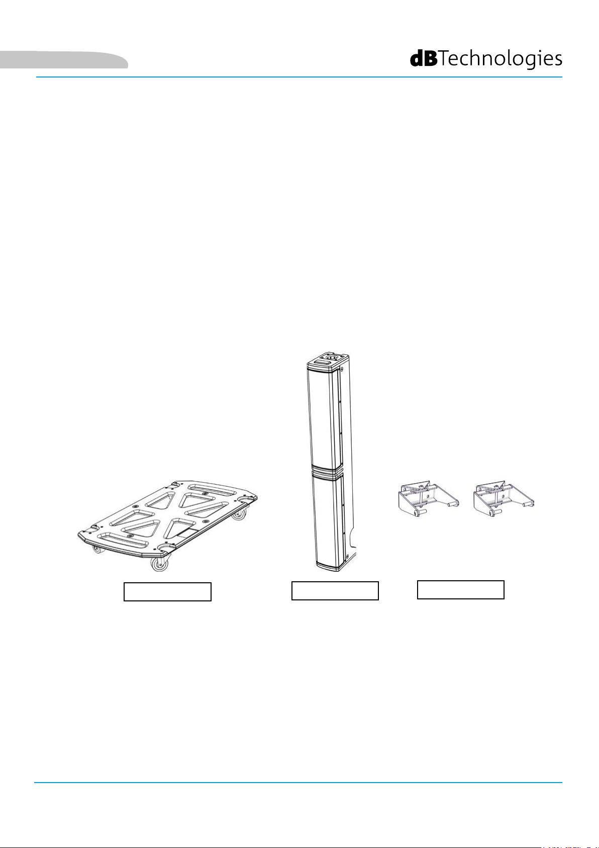
Diversi accessori sono inclusi nella confezione ed altri ne facilitano la movimentazione (carrello DO-ES212) e l’uso
in installazione ssa (staffe a muro WB-44). Le caratteristiche salienti sono:
• sistema compatto e di qualità, facilmente trasportabile, con congurazioni: MONO, STEREO, DOUBLE
COLUMN (con l’utilizzo di un secondo sistema)
• soluzioni acustiche ottimizzate per garantire ottima qualità sonora in un ampio range di frequenze e
perfetta intelligibilità del parlato
• amplicatore digitale di nuova generazione (1200 W RMS) DIGIPRO G4 con PFC.
• 1 ingresso MIC/INSTRUMENT, 2 ingressi LINE/MIC (congurazione stereo), connessione Bluetooth®
• display OLED ed interfaccia compatta con pulsante rotativo per la completa congurazione del sistema.
CONTENUTO DELLA CONFEZIONE
• 1 subwoofer ES1203SUB e 2 top ES1203TOP
• 1 palo telescopico montabile (terminale lettato M20)
• 3 cavi per il collegamento dei top al subwoofer (2 da 7 m per la congurazione stereo, 1 da 2.5 m per
la congurazione mono) e 4 clip per l’organizzazione del cablaggio
• 2 cover accoppiabili per il trasporto del sistema, dei cavi e del palo
• fusibile per l’utilizzo a 100-120V~
• cavo di alimentazione
• documentazione
RIFERIMENTI PER L’UTENTE
Per utilizzare al meglio il vostro sistema ES-1203 consigliamo di:
• leggere il manuale d’uso quick start presente nella confezione e questo manuale d’uso completo in
ogni sua parte e conservarlo per tutta la durata di vita del prodotto.
• registrare il prodotto sul sito http://www.dbtechnologies.com nella sezione “SUPPORTO”.
• conservare prova d’acquisto e GARANZIA (Manuale d’uso “sezione 2”).
ES-1203 Cod. 420120253 REV. 1.0
6
Page 7
Italiano
CARATTERISTICHE MECCANICHE ED ACUSTICHE
DIMENSIONI
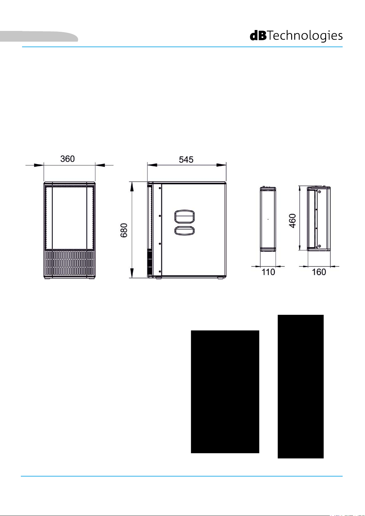
Il sistema ES1203 misura:
SUBWOOFER: 360 mm x 680 mm x 545 mm
TOP: 110 mm x 460 mm x 160 mm
COPERTURA ACUSTICA
La copertura acustica di un singolo top di ES1203
è 60° (verticale) e 97° (orizzontale). Il coverage è
asimmetrico.
Quando i 2 top sono montati uno sull’altro (vedi
la sezione relativa) è possibile indirizzare verso il
basso o l’alto la copertura tramite digital steering
(selezionabile tramite l’interfaccia utente).
ES-1203 Cod. 420120253 REV. 1.0
7
Page 8
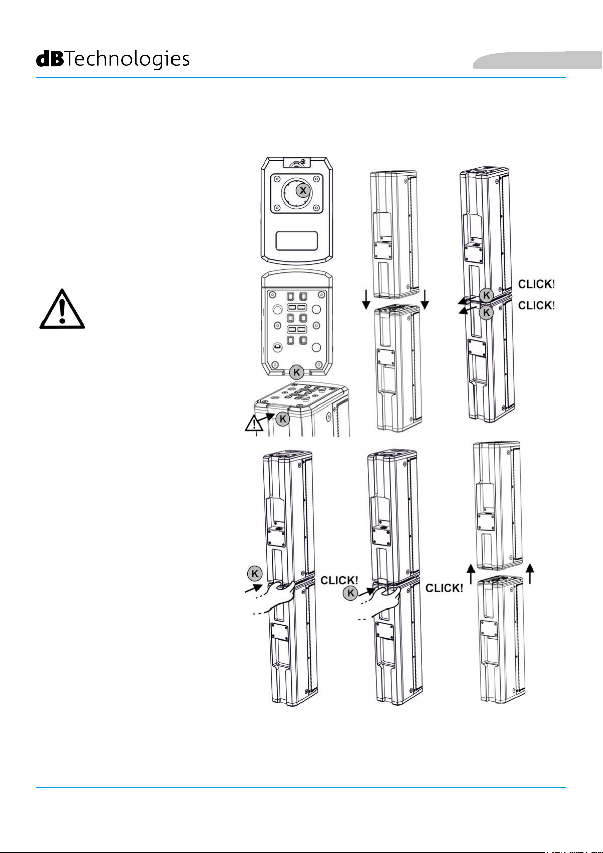
MONTAGGIO (E SMONTAGGIO) DI 2 TOP (CONFIGURAZIONE MONO)
In congurazione mono, è necessario
assemblare 2 top (ES1203TOP) l’uno
sull’altro.
Ogni top è caratterizzato da due lati.
Un lato presenta un foro [X] di diametro
36 mm per l’inserimento del top su palo.
Il lato opposto ha un sistema di
bloccaggio con una leva posteriore di
sicurezza [K].
ATTENZIONE!
• PRIMA DEL MONTAGGIO
ASSICURARSI CHE LE LEVE
DI SICUREZZA [K] SIANO
SPINTE VERSO L’INTERNO
E NON RILASCIATE (VERSO
L’ESTERNO).
Italiano
• Rovesciare uno dei 2 top come
mostrato in gura
• Porre i 2 top l’uno sull’altro
allineando i 2 sistemi di bloccaggio
• Esercitare pressione in modo che i 2
sistemi di bloccaggio si incastrino.
Quando il montaggio è avvenuto
correttamente, le 2 leve di sicurezza
posteriori [K] si muovono verso
l’esterno (posizione rilasciata), con
un “click” ciascuna.
Per smontare i 2 top:
• Premere le 2 leve di sicurezza
posteriori
• Rimuovere i 2 top
ES-1203 Cod. 420120253 REV. 1.0
8
Page 9
Italiano
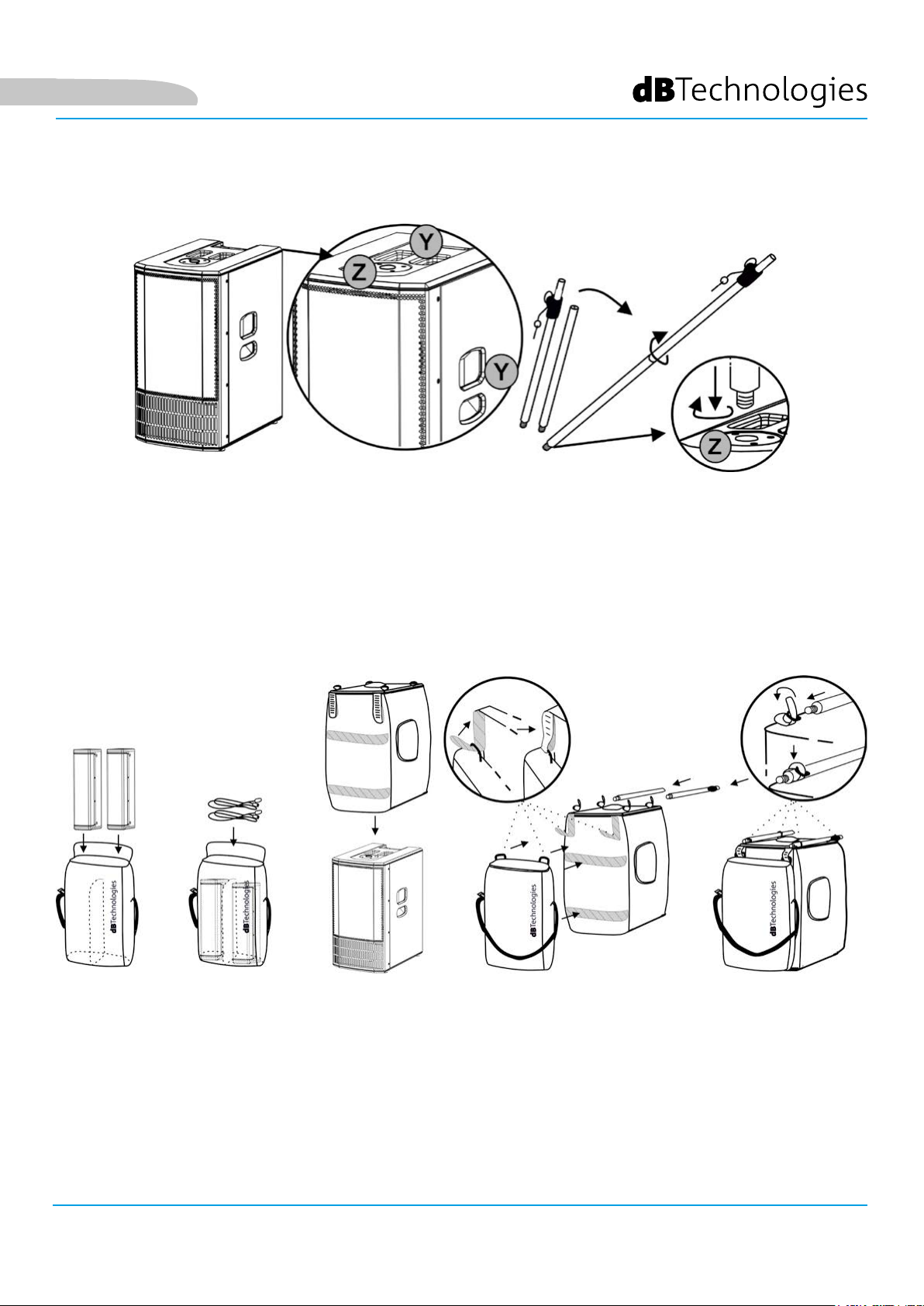
MONTAGGIO DEL PALO TELESCOPICO FORNITO SUL SUBWOOFER
Il subwoofer (ES1203 SUB) è dotato di 3 maniglie per il trasporto [Y]: 2 laterali ed una superiore.
Nel lato superiore è presente anche un foro lettato M20 [Z] per l’inserimento del palo telescopico a corredo.
Per montare il palo telescopico:
• Avvitare con movimento destrorso la parte superiore (telescopica) su quella inferiore (ssa)
• Avvitare con movimento destrorso il palo così ottenuto nel foro [Z]
Il palo regolabile in altezza si inserisce nel foro [X] di un top singolo o di un doppio top in congurazione
MONO. Consultare il capitolo 2 TIPI DI CONFIGURAZIONE per ulteriori informazioni e per le altezze massime
ammesse nell’installazione.
UTILIZZO DELLE COVER DI PROTEZIONE
La borse di protezione fornite a corredo sono 2. Per la protezione del sistema:
• Inserire i 2 top ed i cavi nella cover più piccola. Notare che si può trasportare separatamente grazie alla
tracolla
• Inserire la cover più grande dall’alto sul subwoofer
• Agganciare le due cover fra loro utilizzando le bande di velcro come mostrato. 2 bande sono sul retro delle
2 cover, 2 bande più piccole vengono inserite negli occhielli della cover dei top
• Inserire le 2 parti del palo telescopico nei 4 occhielli superiori della cover del subwoofer, regolandone le
cinghie
ES-1203 Cod. 420120253 REV. 1.0
9
Page 10
Italiano
CARATTERISTICHE DELLA SEZIONE DI AMPLIFICAZIONE E DI CONTROLLO
L’amplicatore digitale in classe D, è il
cuore della serie ES. Il sistema è silenzioso
ed il controllo è afdato a un potente DSP
dedicato che gestisce diversi parametri. Questi
sono completamente congurabili grazie
all’interfaccia di controllo.
La potenza di amplicazione sonora è di 1200
W RMS.
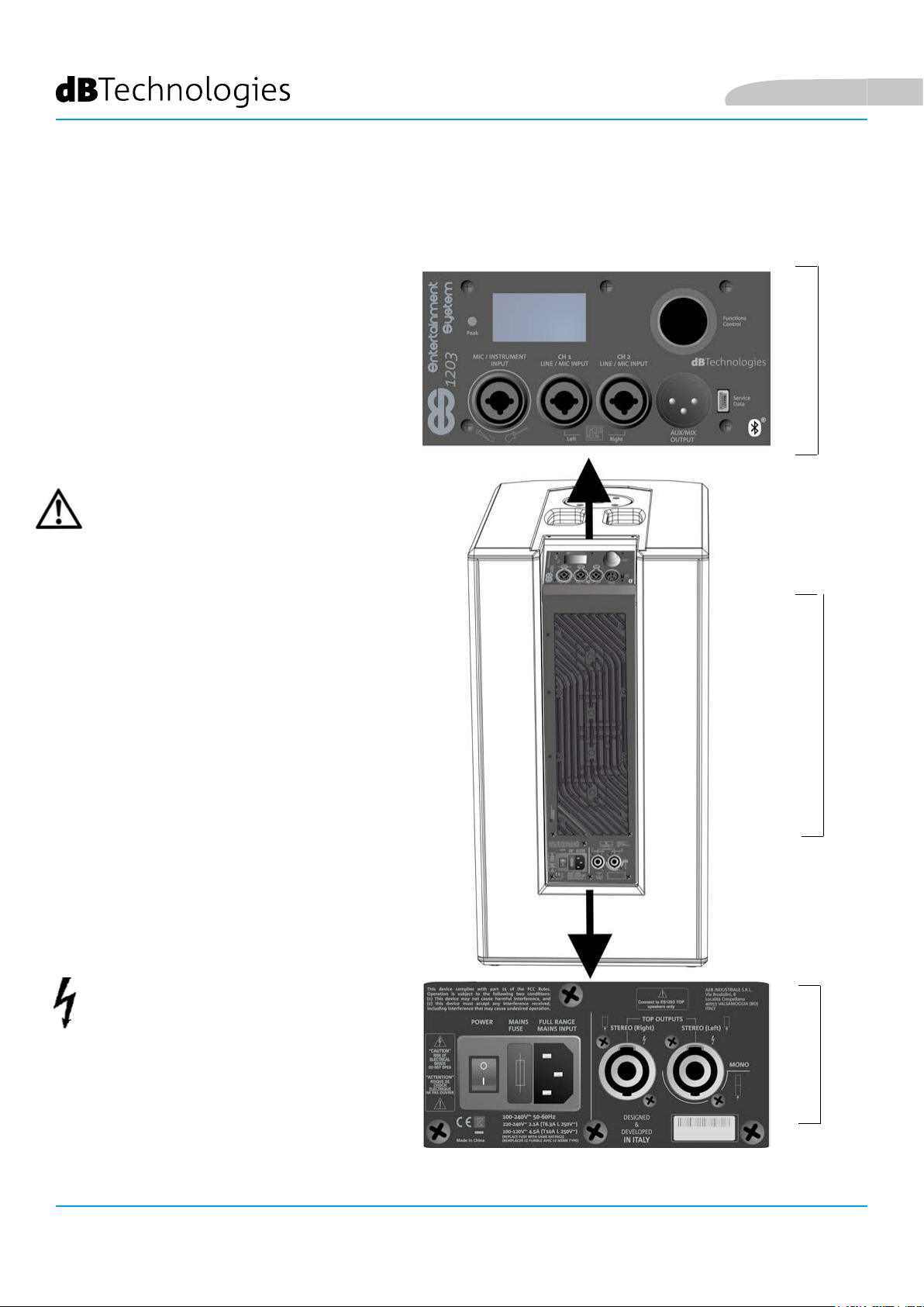
Il pannello di ES1203 è caratterizzato da:
• Sezione di Input, Output e Controllo
• Sezione di Alimentazione e Collegamento
dei top
ATTENZIONE!
• Non ostruire le alette posteriori di
raffreddamento dell’amplicatore. In caso
di surriscaldamento eccessivo, il volume
audio viene ridotto gradualmente no
alla stabilizzazione termica del modulo. Il
livello viene ristabilito automaticamente al
raggiungimento della corretta temperatura
di funzionamento.
• Non tentare in nessun modo di aprire
l’amplicatore.
• In caso di malfunzionamento, interrompere
immediatamente l’alimentazione,
scollegando il modulo dalla rete, e
contattare un riparatore autorizzato.
• Utilizzare solo i cavi in dotazione.
• Il sistema viene fornito con un fusibile già
montato per operare nel range 220-240
V. Se è necessario operare nel range di
tensione 100-120 V:
SEZIONE DI INPUT,
OUTPUT E DI CONTROLLO
AMPLIFICATORE
1. Disconnettere ogni connessione,
compresa l’alimentazione.
2. Attendere 5 minuti.
3. Sostituire il fusibile con quello fornito
nella confezione per il range 100-120 V.
ATTENZIONE!
• Non rimuovere mai la griglia frontale di
protezione del prodotto. Per prevenire il
pericolo di scossa elettrica, in caso di
danneggiamento accidentale o sostituzione
della griglia di protezione (da effettuarsi
presso il servizio assistenza), disconnettere
immediatamente l’alimentazione. Non
connettere mai l’alimentazione di rete
mentre la griglia è rimossa.
SEZIONE DI ALIMENTA-
ES-1203 Cod. 420120253 REV. 1.0
10
DEI TOP
ZIONE E COLLEGAMENTO
Page 11
Italiano
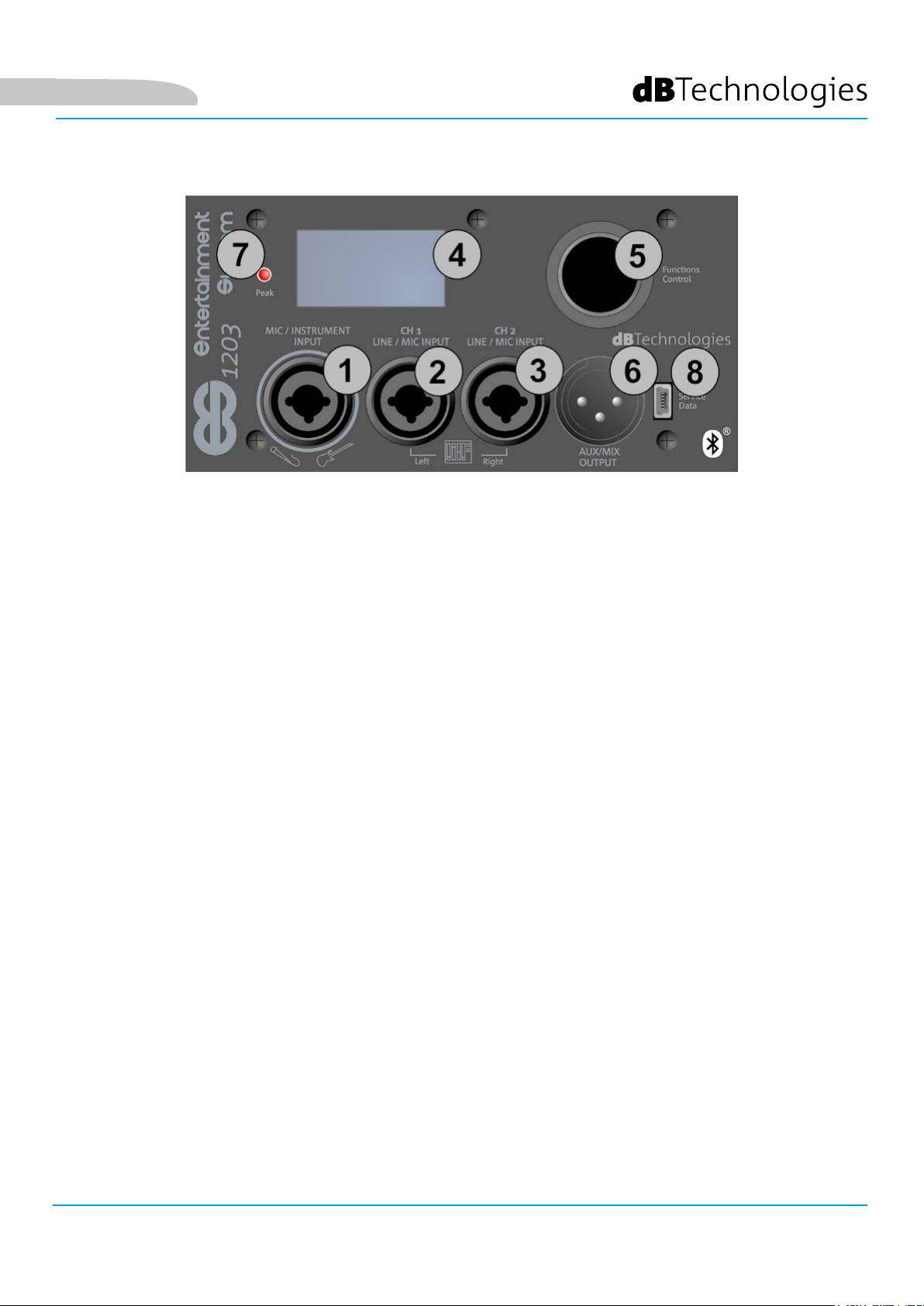
SEZIONE DI INPUT, OUTPUT E DI CONTROLLO
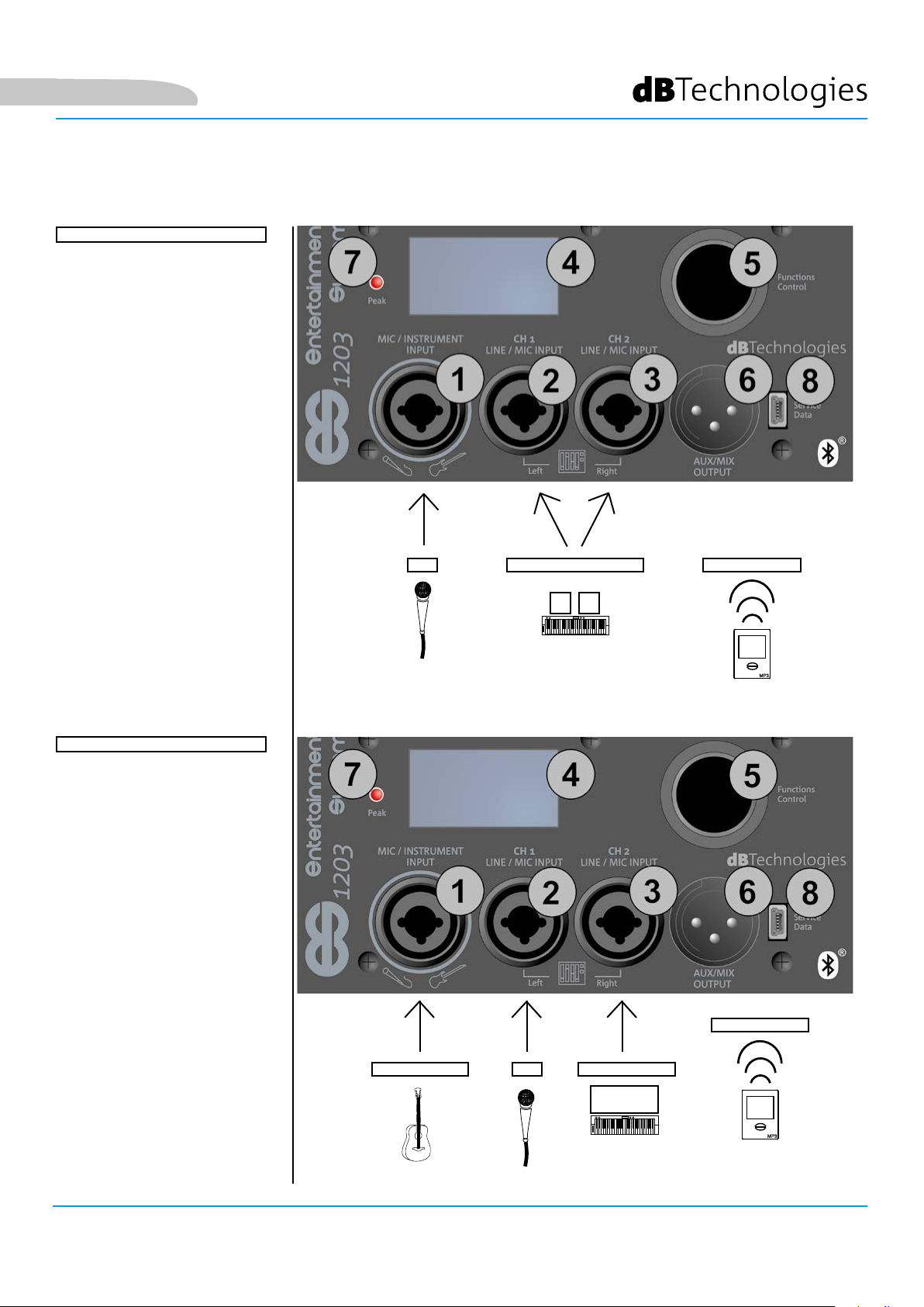
1. Balanced Input MIC/INSTRUMENT
Ingresso combo per connettore XLR o TRS (bilanciato o sbilanciato).
Permette il collegamento di un microfono o di uno strumento dotato di alta impedenza di uscita (ad esempio
una chitarra). Per i dettagli di impostazione del canale, vedi i capitoli 4 e 5.
2. Balanced Input LINE/MIC (CH.1)
Ingresso combo per connettore XLR o TRS (bilanciato o sbilanciato).
Permette il collegamento di un microfono, oppure del segnale di linea (proveniente ad esempio da un mixer o
da uno strumento con impedenza di uscita di linea, come una tastiera elettronica).
Può funzionare come canale mono, oppure come canale sinistro in un collegamento d’ingresso stereo, quando
usato insieme all’input [3]. Per i dettagli di impostazione del canale, vedi i capitoli 4 e 5.
3. Balanced Input LINE/MIC (CH.2)
Ingresso combo per connettore XLR o TRS (bilanciato o sbilanciato).
Permette il collegamento di un microfono, oppure di del segnale di linea (proveniente ad esempio da un mixer
o da uno strumento con impedenza di uscita di linea, come una tastiera elettronica).
Può funzionare come canale mono, oppure come canale destro in un collegamento di ingresso stereo, quando
usato insieme all’input [2]. Per i dettagli di impostazione del canale, vedi i capitoli 4 e 5.
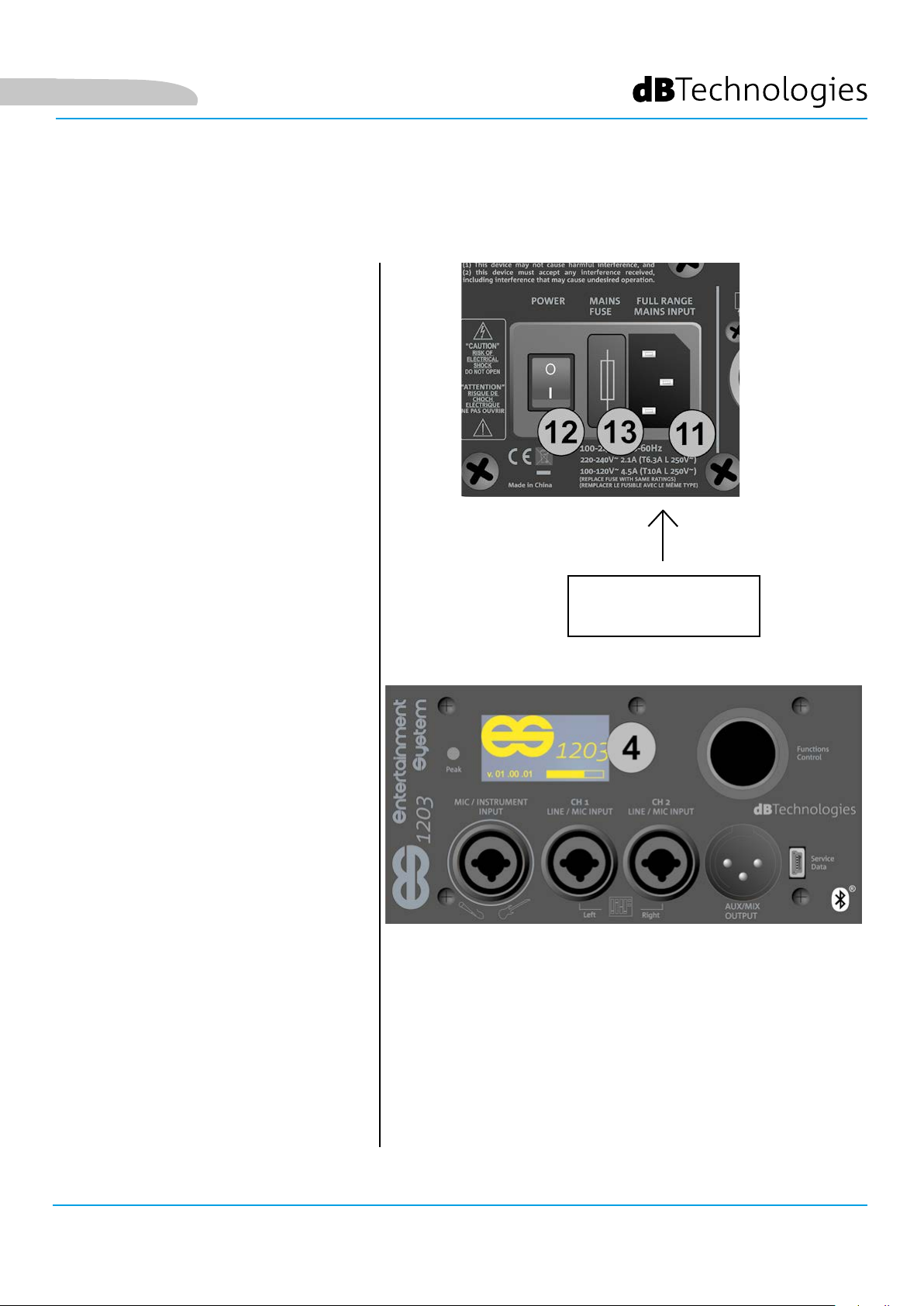
4. Schermo OLED
Schermo che permette di visualizzare tutte le impostazioni di controllo e quelle congurabili del sistema.
5. Functions control (Push-rotary encoder)
Pulsante premibile o ruotabile, per selezionare e confermare un parametro o passare da una schermata all’altra
(scorciatoia) nella navigazione dei menu del sistema.
6. Aux/Mix Output
Uscita per connettore XLR.
Permette il rilancio del segnale di uscita totale (AUX) del sistema ad un secondo speaker.
In alternativa permette il rilancio del canale di uscita appropriato (MIX: sinistro o destro) ad un secondo sistema
ES1203 per ottenere la congurazione DOUBLE COLUMN. Per ulteriori dettagli vedi il capitolo 3.
7. LED “PEAK”
Quando acceso, segnala l’intervento del circuito di protezione dell’amplicatore. Evitare di utilizzare un livello
in ingresso che faccia intervenire spesso tale circuito.
8. PORTA USB “Service/Data”
Porta mini USB-tipo B da utilizzare per l’esclusivo aggiornamento del rmware. Vedi la sezione relativa.
ES-1203 Cod. 420120253 REV. 1.0
11
Page 12
Italiano
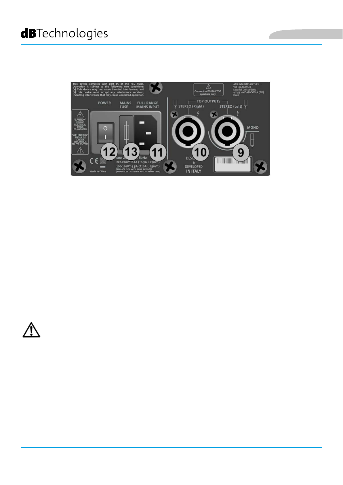
SEZIONE DI ALIMENTAZIONE E COLLEGAMENTO DEI TOP
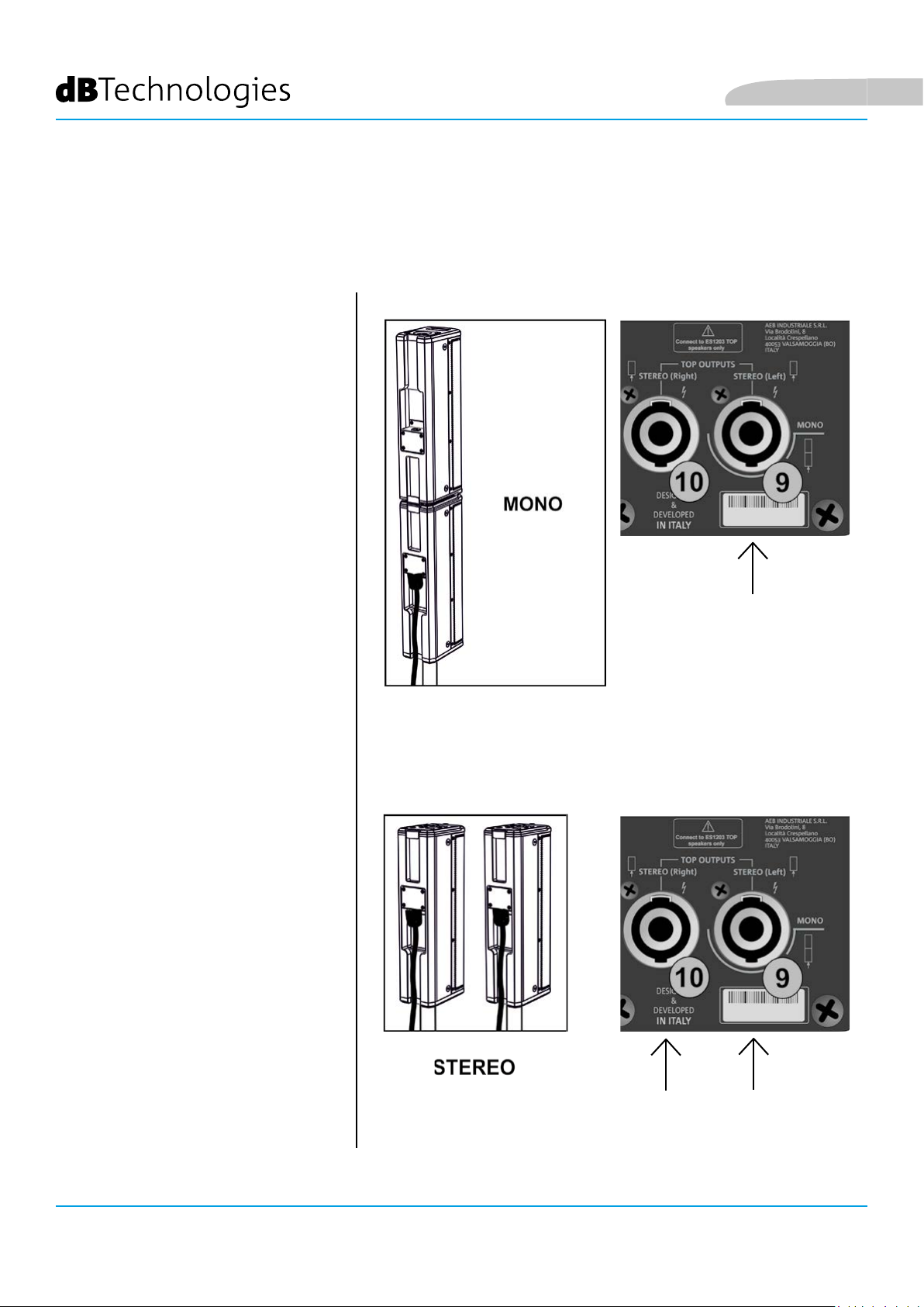
9. Left TOP OUTPUT (MONO)
Connettore per il collegamento di un top (sinistro) in congurazione STEREO, oppure per il collegamento del top
doppio in congurazione mono.
10. Right TOP OUTPUT
Connettore per il collegamento di un top (destro) in congurazione STEREO.
11. MAINS INPUT
Ingresso per connettore VDE. Per il collegamento alla rete elettrica di linea, tramite il cavo in dotazione.
12. PULSANTE ON-OFF
Pulsante per l’accensione (posizione “I”) o lo spegnimento (posizione “O”) del sistema
13. FUSIBILE DI RETE
Alloggiamento del fusibile di rete (sostituibile in caso di danneggiamento o per funzionamento nel range 100120V~)
ATTENZIONE!
• Collegare ai connettori TOP OUTPUTS esclusivamente diffusori passivi modello ES1203TOP!
ES-1203 Cod. 420120253 REV. 1.0
12
Page 13
MAX 70 cm *
Italiano
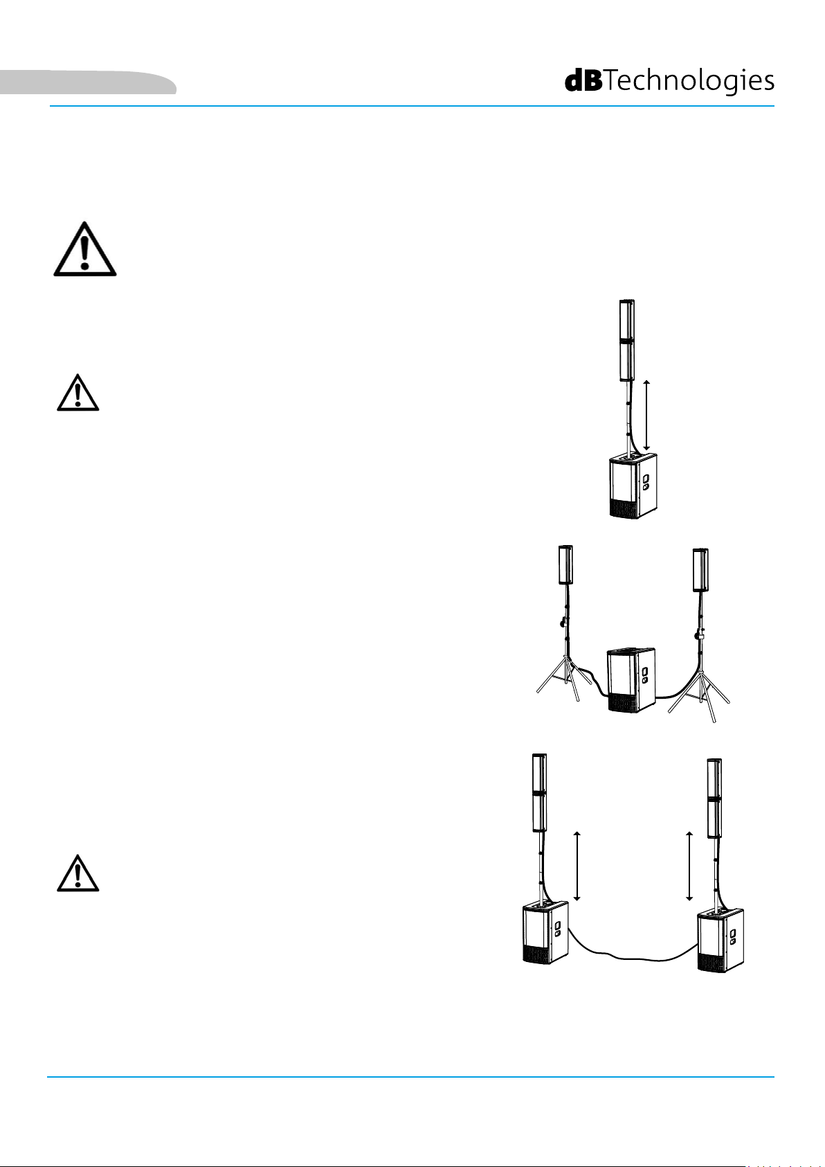
2. TIPI DI CONFIGURAZIONE
• Non sono ammessi tipi di installazione diversi da quelli qui illustrati.
• In nessun caso utilizzare le maniglie del subwoofer per appenderlo
• Vericare sempre che il posizionamento sia stabile, e che l’installazione non costituisca fonte di
pericolo per persone, animali o cose.
A - MONO
In congurazione MONO, la doppia testa è montata sul subwoofer
per mezzo del palo telescopico, regolabile in altezza.
ATTENZIONE!
• In questa congurazione, se la distanza tra il lato superiore
del subwoofer e la base del top inferiore* supera i 70 cm, è
necessario un ssaggio addizionale del sistema a terra tramite
cinghie ed opportuni mezzi meccanici (non forniti).
B - STEREO
In congurazione STEREO, utilizzare 2 treppiedi con palo di
diametro 35 mm (accessorio SK36 TT KIT) come mostrato in gura.
C - DOPPIA COLONNA STEREO
In congurazione DOPPIA COLONNA STEREO (DOUBLE COLUMN),
utilizzare due sistemi MONO collegati tra loro come spiegato nel
paragrafo COLLEGAMENTO DELL’USCITA FRA DUE SISTEMI.
ATTENZIONE!
• In questa congurazione, se la distanza tra il lato superiore
del subwoofer e la base del top inferiore* supera i 70 cm, è
necessario un ssaggio addizionale del sistema a terra tramite
cinghie ed opportuni mezzi meccanici (non forniti).
MAX 70 cm *
INSTALLAZIONE FISSA A MURO
I top del sistema, per ogni tipo di congurazione A, B o C illustrata in precedenza, possono essere montati a
parete, in installazione ssa tramite l’accessorio opzionale WB-44 (kit staffe a muro).
Per ulteriori informazioni vedere il capitolo ACCESSORI.
ES-1203 Cod. 420120253 REV. 1.0
13
Page 14
3. PRIMA ACCENSIONE
COLLEGAMENTO DEI TOP AL SUBWOOFER
CONFIGURAZIONE MONO
In caso di utilizzo di una congurazione
MONO, dopo aver montato le 2
teste come da paragrafo relativo, è
necessario un solo collegamento,
dal subwoofer ad uno dei 2 top:
• Inserire il doppio top sul palo
telescopico montato in precedenza
sul subwoofer (è indifferente che si
scelga il foro [X] dell’uno o dell’altro)
• Utilizzare il cavo da
2.5 m in dotazione.
• Collegare il doppio top nel
connettore inferiore come mostrato
• Effettuare il collegamento del
sub nel connettore MONO [9]
• Utilizzare le clip in
dotazione per ssare il cavo
intorno al palo telescopico
Italiano
CONFIGURAZIONE STEREO
In caso di utilizzo di una
congurazione STEREO:
• Inserire ogni top sul proprio palo (ad
esempio utilizzando il kit SK 36 TT)
• Utilizzare i due cavi da
7 m in dotazione.
• Collegare ogni top come mostrato
• Sul subwoofer, collegare il
connettore del cavo sinistro in [9] e
il connettore del cavo destro in [10].
• Utilizzare le clip in dotazione
per ssare i cavi intorno ai pali
ES-1203 Cod. 420120253 REV. 1.0
14
Page 15
Italiano
COLLEGAMENTO DEGLI INGRESSI
PRIMO ESEMPIO
• Collegare un microfono
al connettore [1]
• Collegare una sorgente
stereo (es. una tastiera o un
mixer) ai due canali [2] e [3]. Il
canale sinistro di uscita della
sorgente va collegato a CH1
[2], il canale destro a CH2 [3].
• Abilitare la trasmissione
Bluetooth® in un
dispositivo multimediale
(es. lettore MP3)
• Per impostare il tipo di
ingresso (MIC/INSTRUMENT
oppure LINE/MIC) e per
le regolazioni di livelli e
parametri fare riferimento
al capitolo 3: PAGINA HOME,
CONTROLLI RAPIDI, MIXER.
MIC
STEREO LINE
R
L
BLUETOOTH®
SECONDO ESEMPIO
• Collegare uno strumento con
alta impedenza di uscita (es.
una chitarra)al connettore [1].
• Collegare un microfono
al connettore [2].
• Collegare l’uscita mono di uno
strumento con impedenza
di uscita di linea (come una
tastiera) al connettore [3].
• Abilitare la trasmissione
Bluetooth® in un
dispositivo multimediale
(es. lettore MP3).
• Per impostare il tipo di
ingresso (MIC/INSTRUMENT
oppure LINE/MIC) e per
le regolazioni di livelli e
parametri fare riferimento
al capitolo 4: PAGINA HOME,
CONTROLLI RAPIDI, MIXER.
INSTRUMENT
MIC
MP3
BLUETOOTH®
LINE (MONO)
L-MONO
MP3
ES-1203 Cod. 420120253 REV. 1.0
15
Page 16
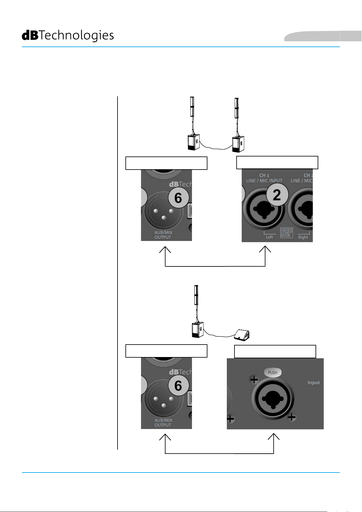
COLLEGAMENTO DELL’ USCITA DEL SISTEMA
CONFIGURAZIONE STEREO A
DOPPIA COLONNA (MIX)
Per il rilancio audio ad
un secondo sistema
ES1203 (congurazione
DOUBLE COLUMN) :
Italiano
• Collegare il connettore di
uscita [6] del primo ES1203
all’ingresso CH1 Left [2]
• Per impostare il
funzionamento stereo
(sinistro e destro), i livelli
e i parametri di uscita fare
riferimento al capitolo 4:
CONTROLLI RAPIDI E MIXER.
RILANCIO DELL’USCITA (AUX)
Per il rilancio audio ad un
altro diffusore amplicato:
• Collegare il connettore
di uscita [6] del primo
ES1203 all’ingresso
Input del secondo
diffusore amplicato.
• Per impostare il livello e
i parametri di uscita fare
riferimento al capitolo 4:
CONTROLLI RAPIDI E MIXER.
PRIMO SISTEMA
ES 1203
SECONDO SISTEMA
MONITOR
ES-1203 Cod. 420120253 REV. 1.0
16
Page 17
Italiano
COLLEGAMENTO DELL’ ALIMENTAZIONE
• Inserire il connettore VDE del cavo
in dotazione in “MAINS INPUT” [11].
• Inserire la spina in una presa
provvista di conduttore di terra.
• Premere il selettore POWER
[12] sulla posizione “I”.
• Lo schermo OLED [4] si illumina.
• In pochi secondi il sistema carica il
rmware e le eventuali impostazioni
salvate dall’utente. La versione del
rmware presente è mostrata nella
pagina di avvio ed una barra mostra
l’avanzamento del caricamento.
ALIMENTAZIONE
(CONNETTORE VDE)
ES-1203 Cod. 420120253 REV. 1.0
17
Page 18
4. PAGINA HOME, CONTROLLI RAPIDI, MIXER
SELEZIONE
(ROTAZIONE)
L’utente visualizza e congura i vari parametri del sistema ES1203
attraverso lo schermo OLED [4] e il pulsante ruotabile [5] nella
sezione Functions Control.
Premendo [5], si seleziona e conferma una pagina o un parametro.
Se la pressione è costante per qualche secondo, si salta a pagine
differenti (scorciatoia).
La rotazione invece permette di navigare tra varie pagine, oppure
all’interno dei parametri di una pagina, oppure di aumentare o
diminuire un valore selezionato.
SELEZIONE
(ROTAZIONE)
CONFERMA
(PRESSIONE)
PAGINA HOME
Functions
Control
Italiano
PAGINA HOME E CONTROLLI RAPIDI
La pagina HOME (gura 1) permette le operazioni fondamentali:
A. impostare il tipo di congurazione
B. selezionare il digital steering (inclinazione del coverage)
C. impostare il volume di sistema MAIN LEVEL
D. accedere alle pagine di congurazione degli ingressi
E. accedere al MENU esteso (vedi capitolo MENU ESTESO DELLE
IMPOSTAZIONI)
Figura 1
Da questa pagina è inoltre possibile accedere ai mixer del
sistema tramite scorciatoia (vedi il paragrafo MIXER DEGLI
INGRESSI, USCITE, AUX).
In congurazione DOPPIA COLONNA STEREO (gura 2)
ogni singolo ES1203 viene identicato come il Master o
lo Slave destro o sinistro. Deve esistere un Master e uno
Slave. Con Master si intende il sistema ES 1203 in cui si
collegheranno gli ingressi e su cui si faranno tutte le
regolazioni che verranno “comandate” di conseguenza
al sistema Slave. Sul sistema Slave quindi le regolazioni
saranno disabilitate.
Figura 2
Vediamo nel dettaglio le operazioni elencate in precedenza:
A. tramite [5] selezionare la casella a sinistra (gura 1) in modo da evidenziarla. Confermare e ruotare per
selezionare la congurazione appropriata. E’ possibile impostare il sistema ES1203 come:
• MONO
• STEREO
• DOPPIA COLONNA STEREO MASTER LEFT (ML)
• DOPPIA COLONNA STEREO SLAVE LEFT (SL)
• DOPPIA COLONNA STEREO MASTER RIGHT (MR)
• DOPPIA COLONNA STEREO SLAVE RIGHT (SR)
ES-1203 Cod. 420120253 REV. 1.0
18
Page 19
Italiano
B. Selezionando e premendo [5] dopo che si è
confermata una congurazione, MONO o DOPPIA
COLONNA STEREO, si può modicare il digital steering
dei top scegliendo fra:
• UP (verso l’alto)
• FAR (nessuna inclinazione)
• DOWN (verso il basso)
Premendo di nuovo [5] si conferma l’opzione scelta
(es. gura 3)
Nella fase di scelta della congurazione,
compare una freccia sinistra e destra
sotto il disegno del sistema.
Nella fase di scelta dello steering,
compare una freccia verso il basso e
verso l’alto sotto il disegno del sistema.
C. Selezionare e confermare MAIN LEVEL (gura 4) per
aumentare o diminuire il volume generale del sistema
ES1203.
D. Selezionare e confermare l’ingresso desiderato
per accedere alla relativa sottopagina. Gli ingressi
disponibili sono:
• CH1
• CH2
• CH3
• BLUETOOTH®
Figura 3
Figura 4
Figura 5
Gli ingressi CH2 e CH3 sono inizialmente
impostati come un unico canale stereo (L+R).
Una volta effettuato l’accesso alla sottopagina
è possibile, selezionando il tipo di ingresso,
utilizzarli come 2 canali mono separati.
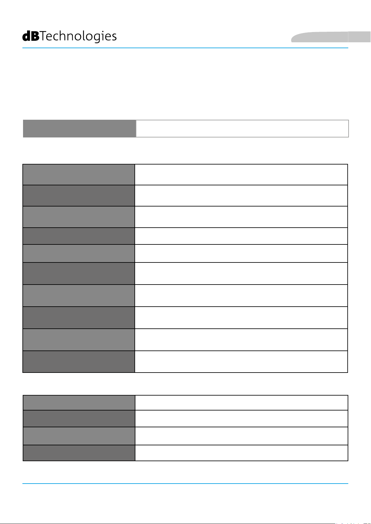
Per gli ingressi CH1, CH2, CH3 la tabella sotto mostra i
parametri regolabili:
NOME PARAMETRO RANGE
NOME PARAMETRO RANGE
GAIN
GAIN
LEVEL
LEVEL
TYPE
TYPE
EQ FILTRI APPLICABILI A: INGRESSO MICROFONICO, INSTRUMENT O LINE
EQ FILTRI APPLICABILI A: INGRESSO MICROFONICO, INSTRUMENT O LINE
AUX
AUX
PAN
PAN
LIVELLO DI USCITA (MANDATA AL MIXER DI INGRESSO)
LIVELLO DI USCITA (MANDATA AL MIXER DI INGRESSO) -∞ ÷ 3 dB
MIXER DELLE MANDATE AUSILIARIE (NON SELEZIONABILE IN CASO DI
MIXER DELLE MANDATE AUSILIARIE (NON SELEZIONABILE IN CASO DI
EFFETTO DI PANNING (NON SELEZIONABILE IN CASO DI CONFIGURAZIONE
EFFETTO DI PANNING (NON SELEZIONABILE IN CASO DI CONFIGURAZIONE
GUADAGNO DI INGRESSO
GUADAGNO DI INGRESSO [0, 10, 20] dB
TIPO DI INGRESSO
TIPO DI INGRESSO
CONFIGURAZIONE DOUBLE COLUM)
CONFIGURAZIONE DOUBLE COLUM)
MONO)
MONO)
Figura 6
[0, 10, 20] dB
-∞ ÷ 3 dB
CH1: MIC/INST - CH2,
CH1: MIC/INST - CH2,
CH3:MIC/LINE
CH3:MIC/LINE
VEDI TABELLA A
VEDI TABELLA A
PAG. 21
PAG. 20
-∞ ÷ 3 dB
-∞ ÷ 3 dB
VEDI PARAGRAFO: MIXER DI
VEDI PARAGRAFO: MIXER DI
INGRESSI, USCITE, AUX
INGRESSI, USCITE, AUX
L ÷ R
L ÷ R
ES-1203 Cod. 420120253 REV. 1.0
19
Page 20
In particolare, nel sottomenu EQ sono selezionabili questi ltri (gure 7,8,9):
INGRESSO TIPO DI FILTRO RANGE
Italiano
MIC PASSA ALTO (HP) / ANTIFEEDBACK
INSTRUMENT/LINE
LF: SHELVING / MF: SEMIPARAMETRICO / HF: SHELVING
PASSA ALTO (HP): 50 ÷ 200 Hz
ANTIFEEDBACK: 500 ÷ 12000 Hz
150 ÷ 4000 Hz (centro-banda)
INSTRUMENT/ LINE FILTER
Figura 8
La sottopagina del canale BLUETOOTH® stereo (gura 10) permette di impostare:
LF/HF: -6 ÷ 4 dB
MF: -6 ÷ 4 dB
Figura 7
Figura 9
NOME PARAMETRO RANGE
ON/OFF
LEVEL
OPTION
AUX
LIVELLO DI USCITA (MANDATA AL MIXER INTERNO) -∞ ÷ 3 dB
PASSWORD (PASSWORD DEL SISTEMA BLUETOOTH®) 4 caratteri alfanumerici
MIXER DELLE MANDATE AUSILIARIE (NON SELEZIONABILE IN CASO DI
ACCENSIONE DEL RICEVITORE ON/OFF
GAIN (GUADAGNO DELL’INGRESSO) 0 ÷ 15 dB
NAME (NOME DEL SISTEMA BLUETOOTH®)
CONFIGURAZIONE DOUBLE COLUMN)
E. Selezionare e confermare la casella MENU per accedere al MENU esteso
(vedi capitolo MENU ESTESO DELLE IMPOSTAZIONI)
16 caratteri alfanumerici
-∞ ÷ 3 dB
VEDI PARAGRAFO MIXER DI
INGRESSI, USCITE, AUX
Figura 10
ES-1203 Cod. 420120253 REV. 1.0
20
Page 21
Italiano
RITORNO ALLA PAGINA HOME DURANTE LA NAVIGAZIONE
Quando ci si trova in una sottopagina, per ritornare alla pagina HOME
occorre selezionare e confermare il simbolo mostrato in gura 10.
In alternativa, tenere premuto il pulsante [5] per qualche secondo
(scorciatoia).
MIXER DI INGRESSI, USCITE, AUX
Dalla pagina HOME, tenendo premuto per alcuni
secondi il pulsante [5], si accede ai mixer di ingressi,
uscite ed AUX (ausiliari). Le pagine principali sono
mostrate in gura 11.
In congurazione DOPPIA COLONNA
STEREO se si sta operando sul sistema
SLAVE, non si può effettuare nessuna
regolazione. Tutti i parametri saranno
impostati sul sistema MASTER.
Figura 10
Le pagine mixer sono:
• INPUTS mixer
• OUTPUTS mixer
• AUX mixer
Per spostarsi tra una di queste 3 pagine, selezionare
la scritta INPUTS, OUTPUTS, AUX, confermare e
ruotare il pulsante [5].
Nella pagina INPUTS sono visualizzati i livelli di CH1,
CH2, CH3 e Bluetooth®.
Nella pagina OUTPUTS i livelli relativi alla sola
sezione separata del Subwoofer e alla sezione MAIN
(totale) del sistema.
Nella sezione AUX sono presenti i livelli dei canali
gestiti come bus ausiliari nel mixer.
Quest’ultima sezione è particolarmente utile nel caso
si voglia ottenere un monitoraggio personalizzato
assegnato all’uscita AUX [6].
Consideriamo il caso della congurazione di gura
12, in cui il sistema ES1203, tramite l’uscita [6] è
collegato ad un monitor.
E’ possibile ad esempio, tramite la pagina mixer
INPUTS, miscelare opportunamente 4 sorgenti
collegate in ingresso al sistema, e farne suonare solo
2 sul monitor collegato, regolandone i livelli AUX in
maniera indipendente.
Figura 11
Figura 12
ES-1203 Cod. 420120253 REV. 1.0
21
Page 22
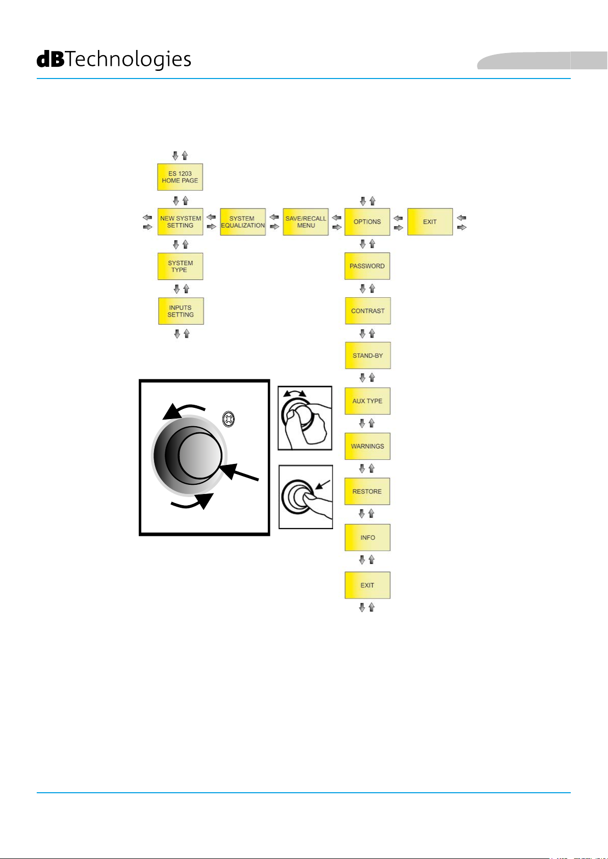
5. MENU ESTESO DELLE IMPOSTAZIONI
Italiano
SELEZIONE
(ROTAZIONE)
Functions
Control
CONFERMA
(PRESSIONE)
SELEZIONE
(ROTAZIONE)
E’ possibile congurare in dettaglio il sistema ES1203 accedendo al MENU dalla pagina HOME.
Le pagine principali sono:
• NEW SYSTEM SETTING
• SYSTEM EQUALIZATION
• SAVE/RECALL MENU
• OPTIONS
Come mostrato nella gura sopra, una volta effettuato l’accesso a NEW SYSTEM SETTING e OPTIONS si accede
ad ulteriori sottopagine di impostazione (che possono differire a seconda della congurazione principale
scelta). Tutte le conferme e selezioni delle pagine sono ottenute con il pulsante rotativo Functions Control come
mostrato.
ES-1203 Cod. 420120253 REV. 1.0
22
Page 23
Italiano
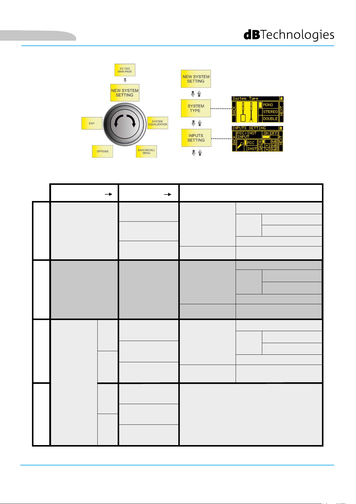
NEW SYSTEM SETTING
La sottopagina permette la congurazione veloce del sistema secondo i parametri riportati nella tabella sotto:
MONO
STEREO
DOUBLE (MASTER)
DOUBLE
SYSTEM TYPE
MONO
STEREO -
STEREO
ML
MR
STEERING
UP
FAR
DOWN
-
UP
FAR
DOWN
CH1, CH2, CH3
BLUETOOTH
CH1, CH2, CH3
BLUETOOTH
CH1, CH2, CH3
BLUETOOTH
INPUTS SETTING
ON/OFF
MIC/INST (CH1)
TYPE
MIC/LINE/L+R (CH2, CH3)
GAIN (0, +10, +20) dB
ON/OFF
ON/OFF
MIC/INST (CH1)
TYPE
MIC/LINE/L+R (CH2, CH3)
GAIN (0, +10, +20) dB
ON/OFF
ON/OFF
MIC/INST (CH1)
TYPE
MIC/LINE/L+R (CH2, CH3)
GAIN (0, +10, +20) dB
ON/OFF
UP
FAR
DOWN
-
DOUBLE (SLAVE)
SL
SR
ES-1203 Cod. 420120253 REV. 1.0
23
Page 24
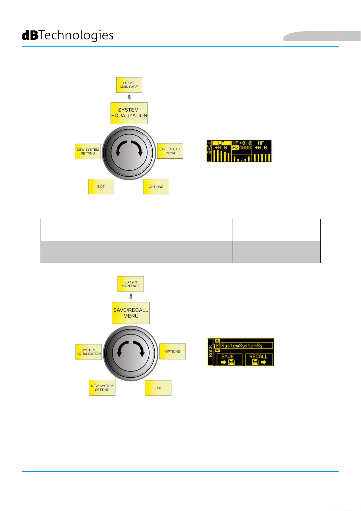
SYSTEM EQUALIZATION
Impostare il ltraggio desiderato da applicare al suono in uscita dal sistema:
Italiano
TIPO DI FILTRO RANGE
LF: SHELVING / MF: SEMIPARAMETRICO / HF: SHELVING
LF/HF: -6 ÷ 4 dB
MF: -6 ÷ 4 dB
150 ÷ 4000 Hz (centro-banda)
SAVE/RECALL MENU
1. Evidenziare l’immagine SAVE per salvare le impostazioni effettuate
2. Attribuire un nome alla congurazione
3. Evidenziare l’immagine RECALL per richiamare una congurazione nominata e salvata in precedenza
ES-1203 Cod. 420120253 REV. 1.0
24
Page 25
Italiano
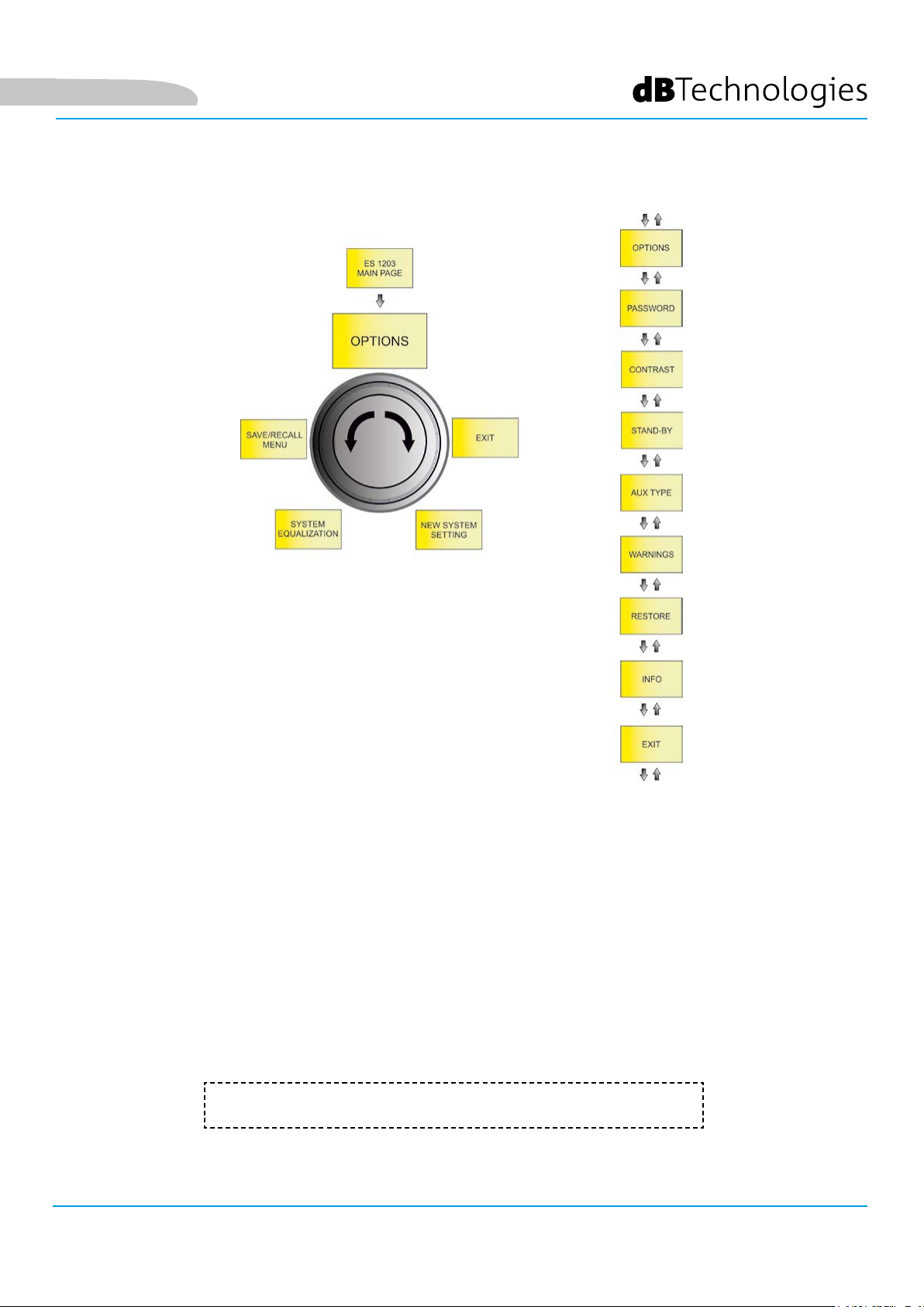
OPTIONS
PASSWORD
1. Abilitare/disabilitare l’uso di una password per proteggere le impostazioni del sistema. Sono disponibili 3
livelli di protezione:
• LEVEL 1 - Lascia la possibilità all’utente di agire sul livello generale MAIN LEVEL e di
caricare i preset ma non di salvarli
• LEVEL 2 - Permette all’utente di intervenire esclusivamente sul livello generale MAIN
LEVEL
• LEVEL 3 - Non permette nessun intervento sulle impostazioni del sistema
2. Immettere una password.
E’ ammesso l’utilizzo di una password esclusivamente numerica di 6 cifre.
In caso di smarrimento, utilizzare il codice SUPERUSER: Q2R5D9.
ES-1203 Cod. 420120253 REV. 1.0
25
Page 26

Italiano
CONTRAST
Regolare il contrasto dello schermo OLED (da 0% a 100% con passi di 5%).
STAND-BY
1. Abilitare/disabilitare l’autospegnimento dello schermo OLED (il sistema rimane acceso)
2. Scegliere il tempo dopo il quale lo schermo si spegne (tra 10 secondi e 10 minuti, con passi di 10 secondi)
AUX TYPE
Come in un mixer, le mandate ausiliarie AUX, possono risentire o meno delle regolazioni fader:
• PRE - la mandata AUX è prelevata a monte delle impostazioni del mixer del sistema,
caso particolarmente adatto all’invio di un segnale ad un monitor separato tramite
l’uscita del sistema ES1203. In questo caso il segnale in uscita è indipendente dalle
impostazioni del mixer interno.
• POST - la mandata AUX è prelevata a valle di tutte le regolazioni del sistema, quindi in
uscita al sistema ES1203 viene mandato un segnale che risente di tutte le impostazioni
del mixer interno.
WARNINGS
Pagina che serve a visualizzare eventuali warning attivi del sistema.
RESTORE
Permette di ritornare alle impostazioni di fabbrica del sistema.
INFO
Visualizza la revisione del rmware del sistema.
EXIT
Permette di uscire dalla pagina OPTIONS.
ES-1203 Cod. 420120253 REV. 1.0
26
Page 27
Italiano
6. ACCESSORI
A completamento della serie, sono previsti come opzionali i seguenti accessori:
• Carrello DO-ES212 - agevola lo spostamento del sistema smontato
• Palo estetico DP-ES1203 - permette di ottenere un’estetica più uniforme in congurazione MONO /
DOPPIA COLONNA STEREO
• Staffe a muro WB-44 - permettono l’installazione a muro di singoli top o di un doppio top (per
l’installazione ssa di ogni tipo di congurazione del sistema)
Vericare i nuovi accessori compatibili su: www.dbtechnologies.com.
DO-ES212
Per ulteriori dettagli sull’utilizzo degli accessori, consultarne le istruzioni a corredo.
ES-1203 Cod. 420120253 REV. 1.0
DP-ES1203
WB-44
27
Page 28

7. RISOLUZIONE DEI PROBLEMI
Il sistema non si accende:
1. Vericare la corretta presenza dell’alimentazione a monte dell’impianto.
2. Vericare che il cavo di alimentazione con connettore VDE sia correttamente inserito, con selettore di
accensione sulla posizione ON.
Il diffusore si accende ma non emette nessun suono:
1. Vericare che il collegamento in ingresso del segnale audio sia correttamente effettuato.
2. Vericare che i cavi utilizzati non siano danneggiati.
3. Vericare i collegamenti tra i top ed il subwoofer.
4. Vericare che il mixer o la sorgente audio sia accesa e mostri chiaramente la presenza di segnale in
uscita.
5. Vericare che le impostazioni dei livelli di ingresso, tipologia di ingresso e di uscita siano adeguate.
Italiano
Il diffusore emette un suono insufciente o distorto:
1. Vericare che i cavi utilizzati non siano danneggiati, nel qual caso sostituirli (un cavo danneggiato può
portare a perdita o alterazione del segnale).
2. Vericare che le impostazioni dei livelli di ingresso, tipologia di ingresso e di uscita siano adeguate.
Lo schermo OLED appare spento:
1. Vericare che non sia inserita l’opzione STAND-BY nel menu OPTION
ES-1203 Cod. 420120253 REV. 1.0
28
Page 29
Italiano
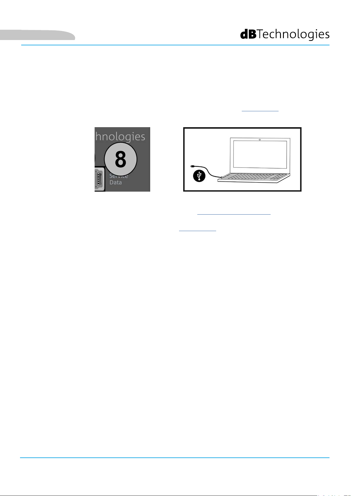
8. AGGIORNAMENTO DEL FIRMWARE
È molto importante mantenere aggiornato il rmware del prodotto, per garantirne una piena funzionalità.
Controllare periodicamente il sito http://www.dbtechnologies.com nella sezione “DOWNLOADS”.
1. Scaricare ed installare USB BURNER MANAGER nella sezione “SOFTWARE & CONTROLLER” sul proprio
computer.
2. Scaricare il le .zip dell’ultimo rmware nella sezione “DOWNLOADS” relativa al proprio prodotto.
3. Collegare il prodotto al PC tramite un cavo USB (non fornito) con il connettore del tipo corretto (vedere questo
dettaglio nel capitolo CARATTERISTICHE DELLA SEZIONE DI AMPLIFICAZION E DI CONTROLLO).
4. Nella schermata dell’USB BURNER MANAGER, in alto a destra, selezionare “Apertura File”.
5. Selezionare il le del rmware precedentemente scaricato.
6. Seguire le operazioni mostrate a video.
7. Cliccare “AGGIORNA”.
ES-1203 Cod. 420120253 REV. 1.0
29
Page 30
9. SPECIFICHE TECNICHE
GENERALE
Tipologia: Sistema tri-amplicato (Mono/Stereo)
DATI ACUSTICI
Italiano
Risposta in frequenza [-10dB]:
Risposta in frequenza [-6dB]:
Max SPL (1 m):
MF-HF mid woofer:
MF-HF voice coil:
LF woofer:
LF voice coil:
Frequenza di crossover:
Direttività:
35 -20000 Hz
41 - 18000 Hz
132 dB
4 x 4” (ogni TOP)
25 mm
2 x 12” (subwoofer)
64 mm
160 Hz (24 dB/oct)
Verticale asimmetrica
Copertura (HxV):
97° x 60° (top singolo)
AMPLIFICATORE
Tipologia:
Classe di amplicazione
Alimentazione
Potenza di amplicazione RMS:
ES-1203 Cod. 420120253 REV. 1.0
30
DIGIPRO G4
Classe D
1 x VDE
1200 W
Page 31

Italiano
TEMPERATURA DI UTILIZZO
Range di Temperatura (ambiente):
PROCESSORE
Controller interno:
Convertitore A/D D/A:
Limiter:
INTERFACCIA UTENTE
Controlli:
INGRESSI E USCITE
Ingressi:
Ingresso contenuti:
Uscita:
-10 +50 °C
DSP 28/56 bit
24 bit/48 kHz
Peak, RMS, Termico
display OLED, push/rotary encoder
1 x Combo (XLR/Jack) MIC/INSTRUMENT, 2 x Combo (XLR/Jack) MIC/LINE
1x Bluetooth®
1 x XLR output
SPECIFICHE DI ALIMENTAZIONE (ASSORBIMENTO / INSTALLAZIONE)
Assorbimento a 1/8 della potenza in
condizioni medie di utilizzo (*):
Assorbimento a 1/3 della potenza in
condizioni massime di utilizzo (**):
Assorbimento con speaker acceso in
assenza di segnale (idle):
Corrente di inrush:
* NOTA PER L’INSTALLATORE: Valori riferiti a 1/8 della potenza, in condizioni medie di funzionamento (programma musicale con clipping raro
o assente). Si consiglia per qualsiasi tipo di congurazione di considerarli i valori minimi di dimensionamento.
** NOTA PER L’INSTALLATORE: Valori riferiti a 1/3 della potenza, in condizioni pesanti di funzionamento (programma musicale con frequente
clipping e intervento del limiter). E’ consigliabile il dimensionamento secondo questi valori in caso di installazioni e tour professionali.
1.1 A (220-240V~) - 2.2 A (100-120V~)
2.1 A (220-240V~) - 4.5 A (100-120V~)
26 W
9.15 A (230 V~)
ES-1203 Cod. 420120253 REV. 1.0
31
Page 32

DIMENSIONI
Italiano
Materiale:
Griglia:
Maniglie:
Montaggio su palo:
Larghezza:
Altezza:
Profondità:
Peso:
Legno (multistrato)
Metallo, spessore 1,5 mm, lavorazione CNC
3 (2 laterali, 1 superiore)
Sì, M20
360 mm (subwoofer) / 110 mm (top)
680 mm (subwoofer) / 460 mm (top)
545 mm (subwoofer) / 160 mm (top)
29.3 kg (subwoofer) / 3.3 kg (top)
Caratteristiche, speciche e aspetto dei prodotti sono soggetti a possibili cambiamenti senza previa
comunicazione. dBTechnologies si riserva il diritto di apportare cambiamenti o miglioramenti nel design o nelle
lavorazioni senza assumersi l’obbligo di cambiare o migliorare anche i prodotti precedentemente realizzati.
A.E.B. Industriale Srl
Via Brodolini, 8
Località Crespellano
40053 VALSAMOGGIA
BOLOGNA (ITALIA)
Tel +39 051 969870
Fax +39 051 969725
www.dbtechnologies.com
info@dbtechnologies-aeb.com
ES-1203 Cod. 420120253 REV. 1.0
32
Page 33

English
CONTENTS
CONTENTS
1. GENERAL INFORMATION .................................................................................................... 34
WELCOME! ....................................................................................................................... 34
INTRODUCTORY OVERVIEW ............................................................................................ 34
PACKAGE CONTENTS ........................................................................................................ 34
USER INFORMATION ........................................................................................................ 34
MECHANICAL AND ACOUSTIC FEATURES ....................................................................... 35
DIMENSIONS ............................................................................................................................................ 35
ACOUSTIC COVERAGE ............................................................................................................................. 35
ASSEMBLY (AND DISASSEMBLY) OF TWO TOPS (MONO CONFIGURATION) ........................................ 36
ASSEMBLING THE SUPPLIED TELESCOPIC POLE ON THE SUBWOOFER ............................................... 37
USING THE PROTECTIVE COVERS ........................................................................................................... 37
AMPLIFIER AND CONTROL SECTION FEATURES ............................................................. 38
INPUT, OUTPUT AND CONTROL SECTION .............................................................................................. 38
AMPLIFIER ................................................................................................................................................ 38
POWER SUPPLY AND TOP CONNECTION SECTION ................................................................................ 38
INPUT, OUTPUT AND CONTROL SECTION .............................................................................................. 39
POWER SUPPLY AND TOP CONNECTION SECTION ................................................................................ 40
2. CONFIGURATION TYPES ..................................................................................................... 41
A - MONO ......................................................................................................................... 41
B - STEREO ......................................................................................................................... 41
C - DOUBLE COLUMN STEREO ........................................................................................ 41
WALL MOUNTING .......................................................................................................... 41
3. FIRST SWITCH-ON ................................................................................................................ 42
CONNECTING THE TOPS TO THE SUBWOOFER ..................................................................................... 42
CONNECTING THE INPUTS ...................................................................................................................... 43
CONNECTING THE SYSTEM OUTPUT ...................................................................................................... 44
CONNECTING POWER ............................................................................................................................. 45
4. HOME PAGE, QUICK CONTROLS, MIXER ........................................................................... 46
5. EXTENDED SETTINGS MENU .............................................................................................. 50
6. ACCESSORIES ........................................................................................................................ 55
7. TROUBLESHOOTING ............................................................................................................ 56
8. UPDATING THE FIRMWARE ................................................................................................ 57
9. TECHNICAL SPECIFICATIONS .............................................................................................. 58
GENERAL .................................................................................................................................................. 58
ACOUSTIC DATA ....................................................................................................................................... 58
AMPLIFIER ................................................................................................................................................ 58
OPERATING TEMPERATURE..................................................................................................................... 59
PROCESSOR .............................................................................................................................................. 59
USER INTERFACE ...................................................................................................................................... 59
INPUTS AND OUTPUTS ............................................................................................................................ 59
POWER SUPPLY SPECIFICATIONS (CONSUMPTION / INSTALLATION) ................................................... 59
DIMENSIONS ............................................................................................................................................ 60
ES-1203 Cod. 420120253 REV. 1.0
33
Page 34

English
1. GENERAL INFORMATION
WELCOME!
Thanks for purchasing a product that was designed and developed in Italy by dBTechnologies! This active,
versatile and ergonomic system is the result of long experience in the eld of sound diffusion. It uses optimised
acoustic and electronic solutions as well as an optimal choice of materials.
INTRODUCTORY OVERVIEW
The ES 1203 is the top of the ES range. The acoustic design provides two tops with 4 x 4" mid-woofers each, with a
“Logarithmic Curved Array” prole and phase plugs to optimise the acoustic coverage. Together with the powerful
wooden subwoofer, equipped with 2 x 12" woofers, this design choice can achieve impressive sonic accuracy and
depth for such a compact system.
Its versatility for both indoor and outdoor use is ensured by a generous array of inputs (including Bluetooth®), by
the possibility of cascading a second system and by the various parameters that can be congured through the
OLED interface.
Various accessories are included in the package and others help with handling (DO-ES212 trolley) and use in a
xed installation (WB-44 wall brackets). The most important features are:
• compact high-quality system that is easy to transport, with the following congurations: MONO,
STEREO, DOUBLE COLUMN (when used with a second system)
• optimised acoustic solutions to ensure excellent sound quality over a wide frequency range and
perfect speech intelligibility
• new generation DIGIPRO G4 digital amplier (1200 W RMS) with PFC.
• 1 MIC/INSTRUMENT input, 2 LINE/MIC inputs (stereo conguration), Bluetooth® connection
• OLED display and compact interface with rotary button for full system conguration.
PACKAGE CONTENTS
• 1 ES1203SUB subwoofer and 2 ES1203TOP tops
• 1 mountable telescopic pole (M20 threaded end)
• 3 cables for connecting the tops to the subwoofer (2 x 7 m for the stereo conguration, 1 x 2.5 m for
the mono conguration) and 4 clips to organise the cabling
• 2 covers, which can be coupled, for transporting the system, cables and pole
• fuse for operation at 100-120 V~
• power cable
• documentation
USER INFORMATION
To use your ES-1203 system in the best way, we recommend that you:
• read the quick start user manual in the package and all of this full user manual, and keep it for the
whole life of the product.
• register the product in the “SUPPORT” section at http://www.dbtechnologies.com.
• keep proof of purchase and the WARRANTY (User manual “section 2”).
ES-1203 Cod. 420120253 REV. 1.0
34
Page 35

English
MECHANICAL AND ACOUSTIC FEATURES
DIMENSIONS
The measurements of the ES1203 system are:
SUBWOOFER: 360 mm x 680 mm x 545 mm
TOP: 110 mm x 460 mm x 160 mm
ACOUSTIC COVERAGE
The acoustic coverage of a single ES1203 top
is 60° (vertical) and 97° (horizontal). The coverage
is asymmetrical.
When the two tops are mounted one on top of
the other (see the related section), you can use
digital steering to direct the coverage upwards
or downwards (selectable through the user
interface).
ES-1203 Cod. 420120253 REV. 1.0
35
Page 36

ASSEMBLY (AND DISASSEMBLY) OF TWO TOPS (MONO CONFIGURATION)
In the mono conguration, you must
assemble the two tops (ES1203TOP) with
one on top of the other.
Each top features two sides.
One side has a 36 mm diameter hole [X]
for inserting the pole.
The other side has a locking system with
a rear safety lever [K].
CAUTION!
• BEFORE ASSEMBLY, MAKE
SURE THAT THE SAFETY
LEVERS [K] ARE PUSHED
INWARDS AND NOT IN
THE RELEASED POSITION
(OUTWARDS).
English
• Flip one of the two tops as shown in
the gure
• Place one of the two tops on the
other with the two locking systems
aligned
• Apply pressure so that the two
locking systems engage. When they
are assembled correctly, the two
rear safety levers [K] move outwards
(released position) and each makes a
“click”.
To disassemble the two tops:
• Press the two rear safety levers
• Remove the two tops
ES-1203 Cod. 420120253 REV. 1.0
36
Page 37

English
ASSEMBLING THE SUPPLIED TELESCOPIC POLE ON THE SUBWOOFER
The subwoofer (ES1203 SUB) has three transport handles [Y]: Two on the sides and one at the top.
There is also an M20 threaded hole [Z] in the top for inserting the telescopic pole provided.
To assemble the telescopic pole:
• Screw the top (telescopic) part onto the lower (xed) part with a clockwise movement
• Screw the resulting pole into the hole [Z] with a clockwise movement
Insert the adjustable pole into the hole [X] on a single top, or on a double top in the MONO conguration.
Refer to chapter 2, CONFIGURATION TYPES, for further information and for the maximum allowed installation
heights.
USING THE PROTECTIVE COVERS
Two protective bags are provided. To protect the system:
• Put the two tops and the cables into the smaller cover. Note that you can transport them separately, thanks
to the shoulder strap
• Put the larger cover over the subwoofer from above
• Attach the two covers together using the Velcro bands as shown. Two bands are at the back of the two
covers, thread the two smaller bands through the eyelets on the cover with the tops in it
• Put the two parts of the telescopic pole into the four eyelets at the top of the subwoofer cover and adjust
the straps
ES-1203 Cod. 420120253 REV. 1.0
37
Page 38

AMPLIFIER AND CONTROL SECTION FEATURES
The core of the ES range is the class-D digital
amplier. The system is silent and is controlled
by a dedicated powerful DSP that manages
various parameters. These are completely
congurable, thanks to the control interface.
The amplier power is 1200 W RMS.
The ES1203 panel features:
• Input, Output and Control section
• Power supply and Top connection section
CAUTION!
• Do not obstruct the amplier cooling ns
at the back. In the event of overheating,
the audio volume is gradually reduced until
the module is thermally stable. The level
is automatically restored on reaching the
correct operating temperature.
• Do not attempt to open the amplier.
• In the event of malfunction, immediately
turn off the power, disconnect the module
from the mains and contact an authorised
repairer.
• Only use the cables provided.
• The system comes with a fuse already tted
for operation in the 220 - 240 V range. If
you need to operate it in the 100-120 V
range:
1. Disconnect all connections, including
the power supply.
2. Wait for 5 minutes.
3. Replace the fuse with the one supplied
in the package for the 100-120 V range.
English
INPUT, OUTPUT AND
AMPLIFIER
CONTROL SECTION
CAUTION!
• Never remove the protective grille from the
front of the product. To prevent an electric
shock hazard, immediately disconnect the
power supply in the event of accidental
damage or when replacing the protective
grille (to be done by the assistance service).
Never connect the mains power with the
grille removed.
POWER SUPPLY AND
ES-1203 Cod. 420120253 REV. 1.0
38
SECTION
TOP CONNECTION
Page 39

English
INPUT, OUTPUT AND CONTROL SECTION
1. Balanced MIC/INSTRUMENT Input
This is an XLR or TRS (balanced or unbalanced) combo connector input.
It allows you to connect a microphone or instrument with a high output impedance (e.g. a guitar). See chapters
4 and 5 for details of the channel settings.
2. Balanced LINE/MIC Input (CH.1)
This is an XLR or TRS (balanced or unbalanced) combo connector input.
It allows you to connect a microphone or line signal (e.g. from a mixer or instrument with a line output
impedance, such as an electronic keyboard).
It can function as a mono channel, or as the left channel in a stereo input connection, when used together with
input [3]. See chapters 4 and 5 for details of the channel settings.
3. Balanced LINE/MIC Input (CH.2)
This is an XLR or TRS (balanced or unbalanced) combo connector input.
It allows you to connect a microphone or line signal (e.g. from a mixer or instrument with a line output
impedance, such as an electronic keyboard).
It can function as a mono channel, or as the right channel in a stereo input connection, when used together
with input [2]. See chapters 4 and 5 for details of the channel settings.
4. OLED Screen
This screen displays all the control settings and congurable system settings.
5. Functions control (Push-rotary encoder)
This push-rotary button selects or conrms a parameter, or passes from one screen to another (shortcut) when
browsing the system menu.
6. Aux/Mix Output
This is an XLR connector output.
It allows you to send the system total output signal (AUX) to a second speaker.
Alternatively, it allows you to send the appropriate channel (MIX: left or right) to a second ES1203 system to
create a DOUBLE COLUMN conguration. See chapter 3 for further details.
7. “PEAK” LED
This lights to indicate when the amplier protection circuit has intervened. Avoid using an input level that
makes this circuit intervene too often.
8. “Service/Data” USB PORT
This is a mini type-B USB port to be used exclusively for updating the rmware. See the related section.
ES-1203 Cod. 420120253 REV. 1.0
39
Page 40

English
POWER SUPPLY AND TOP CONNECTION SECTION
9. Left TOP OUTPUT (MONO)
This connector is for connecting a top (left) in the STEREO conguration, or for connecting the double top in the
mono conguration.
10. Right TOP OUTPUT
This connector is for connecting a top (right) in the STEREO conguration.
11. MAINS INPUT
This is a VDE connector input. It is for connecting the power line, using the cable provided.
12. ON-OFF SWITCH
This switch turns the system on (“I” position) or off (“O”position)
13. MAINS FUSE
This is the mains fuse holder (replaceable when blown or for operation in the 100-120 V~ range)
CAUTION!
• Connect only ES1203TOP passive diffusers to the TOP OUTPUTS connectors!
ES-1203 Cod. 420120253 REV. 1.0
40
Page 41

MAX 70 cm *
English
2. CONFIGURATION TYPES
• Installation types other than those illustrated here are not allowed.
• Never hang the subwoofer by its handles
• Always check that placement is stable and the installation is not a hazard to people, animals or
things.
A - MONO
In the MONO conguration, the double head is mounted on the
subwoofer using a telescopic pole with adjustable height.
CAUTION!
• In this conguration, if the distance from the top of the
subwoofer to the bottom of the lower top is greater than
70 cm, you must also anchor the system to the ground with
straps and suitable mechanical means (not supplied).
B - STEREO
In the STEREO conguration, use two tripods with a 35 mm
diameter pole (SK36 TT kit accessory) as shown in the gure.
C - DOUBLE COLUMN STEREO
In the DOUBLE COLUMN STEREO conguration, use two MONO
systems connected together as explained in the CONNECTING THE
OUTPUT FROM ONE SYSTEM TO ANOTHER paragraph.
CAUTION!
• In this conguration, if the distance from the top of the
subwoofer to the bottom of the lower top is greater than
70 cm, you must also anchor the system to the ground with
straps and suitable mechanical means (not supplied).
MAX 70 cm *
WALL MOUNTING
For each of the conguration types A, B or C illustrated above, you can use the optional WB-44 (wall mounting
brackets kit) accessory to mount the system tops on the wall as part of a xed installation.
See the ACCESSORIES chapter for further information.
ES-1203 Cod. 420120253 REV. 1.0
41
Page 42

3. FIRST SWITCH-ON
CONNECTING THE TOPS TO THE SUBWOOFER
MONO CONFIGURATION
When using a MONO conguration,
mount the two heads as described in
the related paragraph and then you
only need one connection from the
subwoofer to one of the two tops:
• Insert the double top onto
the telescopic pole mounted
previously on the subwoofer (it
makes no difference whether you
choose hole [X] or the other one)
• Use the 2.5 m cable
provided.
• Connect the bottom connector
on the double top as shown
• Connect it to the MONO
connector [9] on the sub
• Use the clips provided to secure
the cable to the telescopic pole
English
STEREO CONFIGURATION
When using a STEREO conguration:
• Insert each top onto its own
pole (e.g. using the SK 36 TT kit)
• Use the two 7 m cables
provided.
• Connect each top as shown
• Connect the left cable connector
[9] and the right cable
connector [10] to the subwoofer.
• Use the clips provided to secure
the cables to the telescopic poles
ES-1203 Cod. 420120253 REV. 1.0
42
Page 43

MP3
English
CONNECTING THE INPUTS
FIRST EXAMPLE
• Connect a microphone
to connector [1]
• Connect a stereo source
(e.g. a keyboard or mixer)
to the two channels [2] and
[3]. The left output channel
from the source should be
connected to CH1 [2], and
the right channel to CH2 [3].
• Enable Bluetooth®
transmission on a multimedia
device (e.g. MP3 player)
• To set the input type (MIC/
INSTRUMENT or LINE/
MIC) and adjust the levels
and parameters, refer to
chapter 3: HOME PAGE,
QUICK CONTROLS, MIXER.
MIC
STEREO LINE
RL
BLUETOOTH®
SECOND EXAMPLE
• Connect an instrument with a
high output impedance (e.g.
a guitar) to connector [1].
• Connect a microphone
to connector [2].
• Connect the mono output
of an instrument with
a line output (such as a
keyboard) to connector [3].
• Enable Bluetooth®
transmission on a multimedia
device (e.g. MP3 player).
• To set the input type (MIC/
INSTRUMENT or LINE/
MIC) and adjust the levels
and parameters, refer to
chapter 4: HOME PAGE,
QUICK CONTROLS, MIXER.
INSTRUMENT
MIC
MP3
BLUETOOTH®
LINE (MONO)
L-MONO
ES-1203 Cod. 420120253 REV. 1.0
43
Page 44

CONNECTING THE SYSTEM OUTPUT
DOUBLE COLUMN STEREO
CONFIGURATION (MIX)
To send the audio to a second
ES1203 system (DOUBLE
COLUMN conguration):
• Connect output connector
[6] on the rst ES1203
to the CH1 Left input [2]
• To set stereo operation (left
and right) and the output
levels and parameters,
refer to chapter 4: QUICK
AND MIXER CONTROLS.
FIRST SYSTEM SECOND SYSTEM
English
OUTPUT (AUX)
To send the audio to
another amplied diffuser:
• Connect output connector
[6] on the rst ES1203
to the Input on the
second amplied diffuser.
• To set the levels and
parameters, refer to
chapter 4: QUICK AND
MIXER CONTROLS.
ES 1203
MONITOR
ES-1203 Cod. 420120253 REV. 1.0
44
Page 45

English
CONNECTING POWER
• Insert the VDE connector of the provided
cable into the “MAINS INPUT” [11].
• Insert the plug into a power
socket with an earth conductor.
• Press the POWER switch
[12] to the “I” position.
• The OLED screen [4] will light up.
• The system will take a few seconds to
load the rmware and any saved user
settings. The current rmware version
will be shown in the start page and a
bar will show the loading progress.
POWER
(VDE CONNECTOR)
ES-1203 Cod. 420120253 REV. 1.0
45
Page 46

4. HOME PAGE, QUICK CONTROLS, MIXER
You can view and congure the various ES1203 system parameters
using the OLED screen [4] and the rotary button [5] in the
Functions Control section.
Pressing [5] selects and conrms a page or parameter. Pressing it
for a few seconds jumps to other pages (shortcut).
Turning it lets you browse the various pages or, if you are in the
parameters on a page, increase or decrease the selected value.
SELECT
SELECT
Functions
Control
CONFIRM
English
HOME PAGE
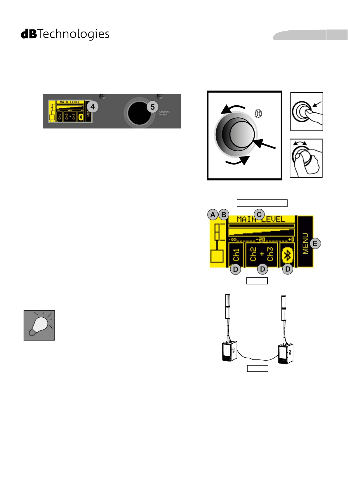
HOME PAGE AND QUICK CONTROLS
You can perform the following basic operations from the HOME
page (gure 1):
A. set the conguration type
B. select the digital steering (coverage angle)
C. set the MAIN LEVEL system volume
D. access the input conguration pages
E. access the extended MENU (see the EXTENDED SETTINGS
MENU chapter)
Figure 1
From this page, you can use a shortcut to access
the system mixers (see the INPUT, OUTPUT AND AUX MIXERS
paragraph).
In the DOUBLE COLUMN STEREO conguration (gure
2), each individual ES1203 is identied as the right or
left Master or Slave. There must be one Master and one
Slave. Master means the ES1203 system to which the
inputs are connected and on which you set up all the
adjustments, which will consequently control the Slave
system. Therefore, adjustments will be disabled on the
Slave system.
Lets see the steps listed above in detail:
Figure 2
A. use [5] to select the left box (gure 1) and highlight it. Conrm and turn to select the appropriate
conguration. You can set the ES1203 system as:
• MONO
• STEREO
• DOUBLE COLUMN STEREO MASTER LEFT (ML)
• DOUBLE COLUMN STEREO SLAVE LEFT (SL)
• DOUBLE COLUMN STEREO MASTER RIGHT (MR)
• DOUBLE COLUMN STEREO SLAVE RIGHT (SR)
ES-1203 Cod. 420120253 REV. 1.0
46
Page 47

English
B. You can change the digital steering of the tops by
selecting and pressing [5] after you have conrmed
a MONO or DOUBLE COLUMN STEREO conguration,
choosing from:
• UP (upwards)
• FAR (no angle)
• DOWN (downwards)
Press [5] again to conrm your chosen option
(e.g. gure 3)
Figure 3
While choosing the conguration,
left and right arrows appear
under the system diagram.
While choosing the steering,
up and down arrows appear
under the system diagram.
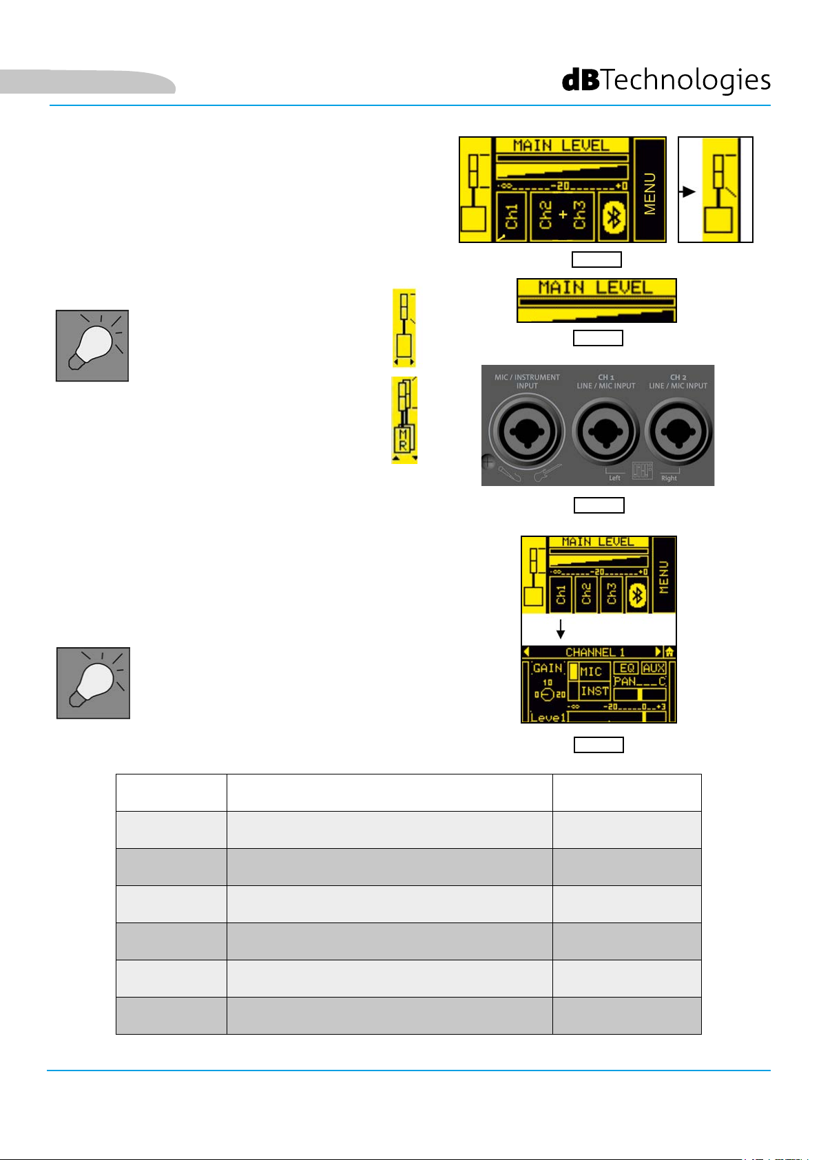
C. Select and conrm MAIN LEVEL (gure 4) to increase
or decrease the overall ES1203 system volume.
D. Select and conrm the desired input to access the
corresponding sub page. The available inputs are:
• CH1
• CH2
• CH3
• BLUETOOTH®
The CH2 and CH3 inputs are initially set as a
single stereo channel (L+R). Once you have
accessed the sub page, you can use them as
two separate mono channels by selecting the
input type.
Figure 4
Figure 5
The table below shows the adjustable parameters for
Figure 6
inputs CH1, CH2 and CH3:
NAME PARAMETER RANGE
GAIN
LEVEL
TYPE
EQ
AUX
PAN
OUTPUT LEVEL (SENT TO THE INTERNAL MIXER) -∞ ÷ 3 dB
FILTERS THAT CAN BE APPLIED TO MICROPHONE, INSTRUMENT OR LINE
AUXILIARY SEND MIXER (NOT AVAILABLE IN THE DOUBLE COLUMN
PANNING EFFECT (NOT AVAILABLE IN THE MONO CONFIGURATION) L ÷ R
INPUT GAIN [0, 10, 20] dB
INPUT TYPE
INPUTS
CONFIGURATION)
CH1: MIC/INST - CH2,
CH3:MIC/LINE
SEE THE TABLE ON
PAG. 48
SEE: INPUT, OUTPUT AND AUX
-∞ ÷ 3 dB
MIXERS PARAGRAPH
ES-1203 Cod. 420120253 REV. 1.0
47
Page 48

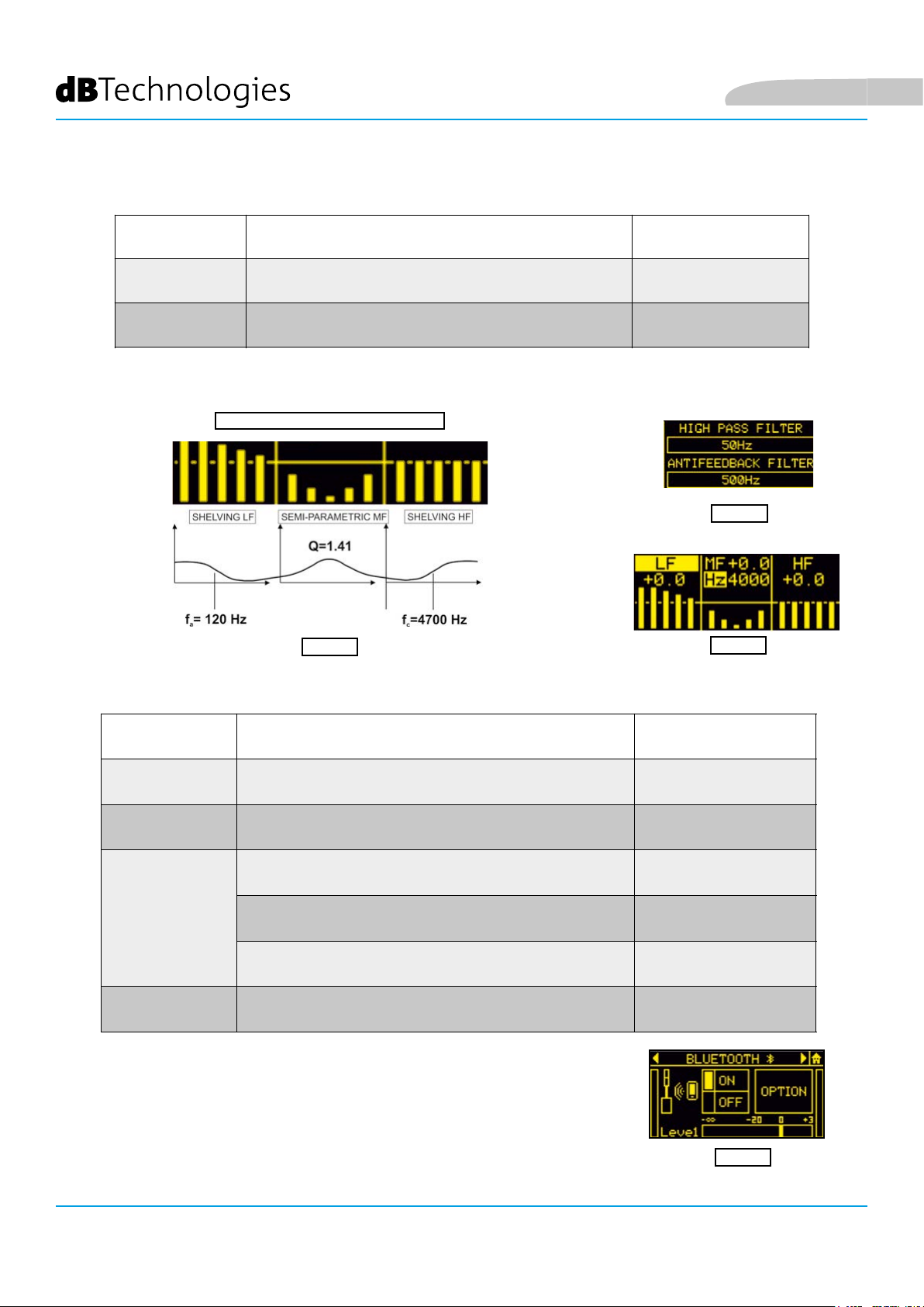
Specically, you can select the following lters from the EQ submenu (gures 7, 8, 9):
INPUT FILTER TYPE RANGE
English
MIC
INSTRUMENT/LINE
LF: SHELVING / MF: SEMIPARAMETRIC / HF: SHELVING
HIGH PASS (HP) / ANTIFEEDBACK
INSTRUMENT/ LINE FILTER
Figure 8
The stereo BLUETOOTH® channel sub page (gure 10) lets you set:
HIGH PASS (HP): 50 ÷ 200 Hz
ANTIFEEDBACK: 500 ÷ 12000 Hz
LF/HF: -6 ÷ 4 dB
MF: -6 ÷ 4 dB
150 ÷ 4000 Hz (CENTER-FREQUENCY)
Figure 7
Figure 9
NAME PARAMETER RANGE
ON/OFF
LEVEL
OPTION
AUX
OUTPUT LEVEL (SENT TO THE INTERNAL MIXER) -∞ ÷ 3 dB
NAME (BLUETOOTH® SYSTEM NAME)
PASSWORD (BLUETOOTH® SYSTEM PASSWORD) 4 NUMERIC DIGITS
AUXILIARY SEND MIXER (NOT AVAILABLE IN DOUBLE COLUMN
RECEIVER ON/OFF ON/OFF
GAIN (INPUT GAIN) 0 ÷ 15 dB
CONFIGURATION)
E. Select and conrm the MENU box to access the extended MENU (see the
EXTENDED SETTINGS MENU chapter)
16 ALPHANUMERIC CHARACTERS
-∞ ÷ 3 dB
SEE THE INPUT AND AUX MIXERS
PARAGRAPH
Figure 10
ES-1203 Cod. 420120253 REV. 1.0
48
Page 49

English
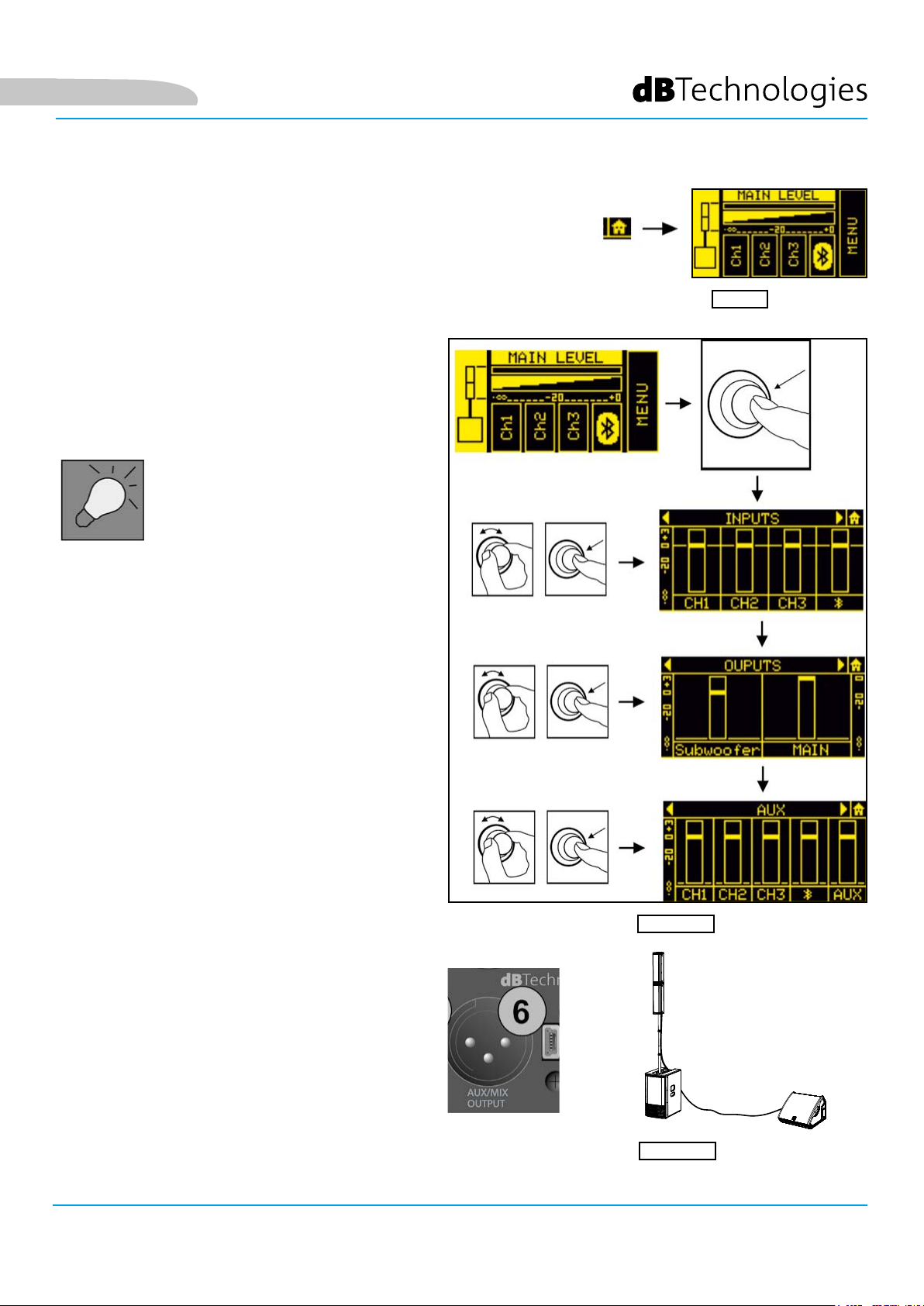
RETURNING TO THE HOME PAGE WHILE BROWSING
To return to the HOME page from a sub page,
select and conrm the symbol shown in gure 10.
Alternatively, hold button [5] pressed for a few seconds
(shortcut).
INPUT, OUTPUT AND AUX MIXERS
From the HOME page, hold button [5] pressed for
a few seconds to access the input, output and AUX
(auxiliary buses) mixer. The main pages are shown in
gure 11.
In the DOUBLE COLUMN STEREO
conguration, you cannot make any
adjustments from the SLAVE system. You
must set all the parameters on the MASTER system.
Figure 10
The mixer pages are:
• INPUTS mixer
• OUTPUTS mixer
• AUX mixer
To enter one of these 3 pages, select the
corresponding word INPUTS, OUTPUTS or AUX,
conrm and turn button [5].
The INPUTS page displays the CH1, CH2, CH3 and
Bluetooth® levels.
The OUTPUTS page only displays the levels of the
separate subwoofer sections and the system MAIN
(total) section.
The AUX section has the levels of the channels that
function as auxiliary buses in the mixer.
The latter section is especially useful when you want
personalised monitoring assigned to the AUX output
[6].
Consider the conguration shown in gure 12, in
which output [6] of the ES1203 system is connected
to a monitor.
You can, for example, use the INPUTS mixer to mix
four sources connected to the system inputs, and
make only two of them play through the connected
monitor by adjusting the AUX levels independently.
Figure 11
Figure 12
ES-1203 Cod. 420120253 REV. 1.0
49
Page 50

5. EXTENDED SETTINGS MENU
English
SELECT
Functions
Control
CONFIRM
SELECT
You can congure the ES1203 system in detail by accessing this MENU from the HOME page.
The main pages are:
• NEW SYSTEM SETTING
• SYSTEM EQUALIZATION
• SAVE/RECALL MENU
• OPTIONS
As shown in the gure above, once you have accessed NEW SYSTEM SETTING and OPTIONS, you can access other
settings sub pages (which differ according to the chosen main conguration). Use the Functions Control rotary
button to conrm and select the pages as shown.
ES-1203 Cod. 420120253 REV. 1.0
50
Page 51

English
NEW SYSTEM SETTING
This sub page lets you quickly congure the system using the parameters listed in the table below:
MONO
STEREO
DOUBLE (MASTER)
DOUBLE
SYSTEM TYPE
MONO
STEREO -
STEREO
ML
MR
STEERING
UP
FAR
DOWN
-
UP
FAR
DOWN
CH1, CH2, CH3
BLUETOOTH
CH1, CH2, CH3
BLUETOOTH
CH1, CH2, CH3
BLUETOOTH
INPUTS SETTING
ON/OFF
MIC/INST (CH1)
TYPE
MIC/LINE/L+R (CH2, CH3)
GAIN (0, +10, +20) dB
ON/OFF
ON/OFF
MIC/INST (CH1)
TYPE
MIC/LINE/L+R (CH2, CH3)
GAIN (0, +10, +20) dB
ON/OFF
ON/OFF
MIC/INST (CH1)
TYPE
MIC/LINE/L+R (CH2, CH3)
GAIN (0, +10, +20) dB
ON/OFF
UP
FAR
DOWN
-
DOUBLE (SLAVE)
SL
SR
ES-1203 Cod. 420120253 REV. 1.0
51
Page 52

SYSTEM EQUALIZATION
Sets the ltering that you want to apply to the system output sound:
English
LF: SHELVING / MF: SEMIPARAMETRIC / HF: SHELVING
SAVE/RECALL MENU
FILTER TYPE RANGE
LF/HF: -6 - 4 dB
MF: -6 - 4 dB
150 - 4000 Hz (band centre)
1. Highlight the SAVE image to save your settings
2. Give a name to the conguration
3. Highlight the RECALL image to recall a named conguration saved previously
ES-1203 Cod. 420120253 REV. 1.0
52
Page 53

English
OPTIONS
PASSWORD
1. Enables/disables the use of a password to protect the systems settings. There are three protection levels:
• LEVEL 1 - Lets you operate at the general MAIN LEVEL and load presets but not save them
• LEVEL 2 - Lets you operate only at the general MAIN LEVEL
• LEVEL 3 - Does not let you change any system settings
2. Enter a password.
You can only use a 6-digit numeric password.
If you lose it, use the SUPERUSER code: Q2R5D9.
ES-1203 Cod. 420120253 REV. 1.0
53
Page 54

English
CONTRAST
Adjusts the OLED screen contrast (from 0% to 100% in steps of 5%).
STAND-BY
1. Enables/disables OLED screen auto power-off (the system remains on)
2. Choose the time after which the screen turns off (from 10 seconds to 10 minutes in steps of 10 seconds)
AUX TYPE
As in a mixer, the AUX sends may be affected by fader adjustments or not:
• PRE - the AUX send is taken before the system mixer settings, which is particularly
suited to using the ES1203 system output for sending a signal to a separate monitor. In
this case, the output signal is independent of the internal mixer settings.
• POST - the AUX send is taken after all the system adjustments, so the ES1203 system
outputs a signal that is affected by all the internal mixer settings.
WARNINGS
This page displays any active system warnings.
RESTORE
Lets you return the system to its factory settings.
INFO
Displays the system rmware revision.
EXIT
Exits from the OPTIONS page.
ES-1203 Cod. 420120253 REV. 1.0
54
Page 55

English
6. ACCESSORIES
The following optional accessories are available to complete the range:
• DO-ES212 trolley - helps you move the disassembled system
• DP-ES1203 design pole - gives you a more uniform appearance in the MONO / DOUBLE COLUMN
STEREO conguration
• WB-44 wall bracket - lets you wall-mount a single top or a double top (for xed installation of any
system conguration type)
Check for new compatible accessories at www.dbtechnologies.com.
DO-ES212
Consult the accompanying instructions for further details on using accessories.
ES-1203 Cod. 420120253 REV. 1.0
DP-ES1203
WB-44
55
Page 56

7. TROUBLESHOOTING
The system will not turn on:
1. Check that the system is connected to a working power supply.
2. Check that the power cable with VDE connector is plugged in properly and that the power switch is in
the ON position.
The diffuser turns on but does not emit any sound:
1. Check that the audio signal input is connected correctly.
2. Check that the cables used are not damaged.
3. Check the connections between the tops and the subwoofer.
4. Check that the mixer or audio source is on and clearly shows an output signal.
5. Check that the input level, input type and output level are suitable.
English
The sound emitted by the diffuser is insufcient or distorted:
1. Check that the cables used are not damaged. If they are, replace them ( a damaged cable may cause
signal loss or alteration).
2. Check that the input level, input type and output level are suitable.
The OLED screen appears to be off:
1. Check that the STAND-BY option in the OPTION menu is not enabled
ES-1203 Cod. 420120253 REV. 1.0
56
Page 57

English
8. UPDATING THE FIRMWARE
It is very important to keep the product rmware updated to ensure full functionality. Periodically check the
“DOWNLOADS” section of the http://www.dbtechnologies.com website.
1. Download and install the USB BURNER MANAGER onto your computer from the “SOFTWARE & CONTROLLER”
section.
2. Download the .zip le for your product from the “DOWNLOADS” section.
3. Connect the product to the PC using a USB cable (not supplied) with the correct connector type (see this detail
in the AMPLIFIER AND CONTROL SECTION FEATURES chapter).
4. Select “Open File” at the top right of the USB BURNER MANAGER screen.
5. Select the previously downloaded rmware le.
6. Follow the instructions shown on the screen.
7. Click “UPDATE”.
ES-1203 Cod. 420120253 REV. 1.0
57
Page 58

9. TECHNICAL SPECIFICATIONS
GENERAL
Type: Tri-amplied system (Mono/Stereo)
ACOUSTIC DATA
English
Frequency response [-10dB]:
Frequency response [-6dB]:
Max SPL (1 m):
MF-HF mid woofer:
MF-HF voice coil:
LF woofer:
LF voice coil:
Crossover frequency:
Directivity:
35 - 20000 Hz
41 - 18000 Hz
132 dB
4 x 4” (each TOP)
25 mm
2 x 12” (subwoofer)
64 mm
160 Hz (24 dB/oct)
Asymmetrical vertical
Coverage (HxV):
97° x 60° (single top)
AMPLIFIER
Type:
Amplication class
Power connection
RMS amplication power:
ES-1203 Cod. 420120253 REV. 1.0
58
DIGIPRO G4
Class D
1 x VDE
1200 W
Page 59

English
OPERATING TEMPERATURE
Temperature Range (ambient):
PROCESSOR
Internal controller:
A/D D/A converter:
Limiter:
USER INTERFACE
Controls:
INPUTS AND OUTPUTS
Inputs:
Built-in input:
Output:
-10 +50 °C
28/56 bit DSP
24 bit/48 kHz
Peak, RMS, Thermal
OLED display, push/rotary encoder
1 x Combo (XLR/Jack) MIC/INSTRUMENT, 2 x Combo (XLR/Jack) MIC/LINE
1x Bluetooth®
1 x XLR output
POWER SUPPLY SPECIFICATIONS (CONSUMPTION / INSTALLATION)
Consumption at 1/8 of the power
under normal operating conditions
(*):
Consumption at 1/3 of the power
under maximum operating
conditions (**):
Consumption with speaker on and no
signal (idle):
Inrush current:
* NOTE FOR THE INSTALLER: Values refer to 1/8 of the power under normal operating conditions (musical program with rare or no clipping).
For any conguration type, we recommend considering them to be the minimum values for dimensioning.
** NOTE FOR THE INSTALLER: Values refer to 1/3 of the power under heavy operating conditions (musical program with frequent clipping
and limiting). We recommend dimensioning according to these values for installations and professional tours.
1.1 A (220 - 240 V~) - 2.2 A (100 - 120 V~)
2.1 A (220 - 240 V~) - 4.5 A (100 - 120 V~)
26 W
9.15 A (230 V~)
ES-1203 Cod. 420120253 REV. 1.0
59
Page 60

DIMENSIONS
English
Material:
Grille:
Handles:
Pole mounting:
Width:
Height:
Depth:
Weight:
Wood (plywood)
Metal, 1.5 mm thick, CNC machined
3 (2 at the sides, 1 on top)
Yes, M20
360 mm (subwoofer) / 110 mm (top)
680 mm (subwoofer) / 460 mm (top)
545 mm (subwoofer) / 160 mm (top)
29.3 kg (subwoofer) / 3.3 kg (top)
Product features, specications and appearance are subject to change without prior notice. dBTechnologies
reserves the right to make changes or improvements in design or manufacturing without any obligation to change
or improve previously manufactured products.
A.E.B. Industriale Srl
Via Brodolini, 8
Località Crespellano
40053 VALSAMOGGIA
BOLOGNA (ITALIA)
Tel +39 051 969870
Fax +39 051 969725
www.dbtechnologies.com
info@dbtechnologies-aeb.com
ES-1203 Cod. 420120253 REV. 1.0
60
Page 61

Deutsch
INHALTSVERZEICHNIS
INHALTSVERZEICHNIS
1. ALLGEMEINE HINWEISE ...................................................................................................... 62
WILLKOMMEN! ................................................................................................................ 62
KURZBESCHREIBUNG ....................................................................................................... 62
INHALT DER VERPACKUNG .............................................................................................. 62
BENUTZERHINWEISE ........................................................................................................ 62
MECHANISCHE UND AKUSTISCHE EIGENSCHAFTEN ...................................................... 63
ABMESSUNGEN ........................................................................................................................................ 63
ABSTRAHLVERHALTEN ............................................................................................................................. 63
MONTAGE (UND DEMONTAGE) DER BEIDEN AUFSÄTZE (MONO-KONFIGURATION) .......................... 64
MONTAGE DER TELESKOPSTANGE AUF DEM SUBWOOFER ................................................................. 65
VERWENDUNG DER SCHUTZHÜLLEN ..................................................................................................... 65
EIGENSCHAFTEN DES VERSTÄRKER- UND CONTROL-BEREICHES .................................. 66
BEREICH FÜR INPUT, OUTPUT UND CONTROL ...................................................................................... 66
BEREICH FÜR VERSORGUNG UND VERBINDUNG DER TOPS ................................................................. 66
BEREICH FÜR INPUT, OUTPUT UND CONTROL ...................................................................................... 67
BEREICH FÜR VERSORGUNG UND VERBINDUNG DER TOPS ................................................................. 68
2. KONFIGURATIONSARTEN .................................................................................................. 69
A – MONO ......................................................................................................................... 69
B – STEREO ........................................................................................................................ 69
C – DOPPEL-STEREO-KONFIGURATION .......................................................................... 69
FESTMONTAGE AN EINER WAND ................................................................................. 69
3. ERSTE INBETRIEBNAHME ................................................................................................... 70
VERBINDUNG DER AUFSÄTZE MIT DEM SUBWOOFER .......................................................................... 70
VERBINDEN DER EINGÄNGE ................................................................................................................... 71
ANSCHLUSS DES SYSTEMAUSGANGES ................................................................................................... 72
ANSCHLUSS DER STROMVERSORGUNG ................................................................................................. 73
4. HOMEPAGE, QUICK CONTROLS, MIXER ............................................................................ 74
5. ERWEITERTES EINSTELLUNGS-MENÜ ................................................................................ 78
6. ZUBEHÖR .............................................................................................................................. 83
7. TROUBLESHOOTING ............................................................................................................ 84
8. FIRMWARE-UPDATE ............................................................................................................ 85
9. TECHNISCHE DATEN ............................................................................................................ 86
ALLGEMEINES .......................................................................................................................................... 86
AKUSTISCHE DATEN ................................................................................................................................. 86
VERSTÄRKER ............................................................................................................................................ 86
EINSATZTEMPERATUR ............................................................................................................................. 87
PROZESSOR .............................................................................................................................................. 87
USER INTERFACE ...................................................................................................................................... 87
EIN- UND AUSGÄNGE .............................................................................................................................. 87
DATEN ZUR STROMVERORGUNG (VERBRAUCH / INSTALLATION) ........................................................ 87
ABMESSUNGEN ........................................................................................................................................ 88
ES-1203 Cod. 420120253 REV. 1.0
61
Page 62

Deutsch
1. ALLGEMEINE HINWEISE
WILLKOMMEN!
Danke, dass Sie ein Produkt erworben haben, das von dBTechnologies in Italien entworfen und entwickelt
wurde! Dieses aktive, vielseitige und ergonomische System ist das Ergebnis langjähriger Erfahrung im Bereich
Klangwiedergabe, in das optimierte Lösungen im akustischen und elektronischen Bereich sowie bei der
Materialauswahl Eingang fanden.
KURZBESCHREIBUNG
Das ES 1203 ist das Flaggschiff der ES-Serie. Es umfasst 2 Lautsprecheraufsätze ("Tops") und 4 Mid-Woofer (jeder 4
Zoll groß) mit einem "Logarithmic Curved Array"-Prol und Phase-Plug zur Optimierung der Akustikleistung. Mit
dem leistungsstarken Subwoofer aus Holz, in dem zwei 12-Zoll-Woofer verbaut sind, ermöglicht dieses DesignKonzept eine für ein so kompaktes System beachtliche Präzision und Klangtiefe.
Die vielseitige Verwendung in Räumen und Außenbereichen wird durch die Bereitstellung mehrerer Eingänge
(mit Bluetooth® Technologie), die Möglichkeit der Verbindung mit einem zweiten System sowie durch eine
umfassende Kongurierbarkeit verschiedener Parameter über eine OLED-Schnittstelle gesichert.
Im Lieferumfang inbegriffen ist verschiedenes Zubehör; andere Bestandteile des Lieferumfanges ermöglichen
machen das System mobil (Rollenuntersatz DO-ES212) oder an einem festen Ort einsetzbar (Wandverankerungen
WB-44). Die herausragenden Features sind:
• kompaktes, hochwertiges, leicht transportierbares System mit folgenden Kongurationen: MONO,
STEREO, DOUBLE COLUMN (bei Verwendung eines Zweitsystems)
• optimierte Akustiklösungen zur Sicherstellung hoher Klangqualität in einem breiten Frequenzspektrum
und optimal verständlicher Sprachwiedergabe
• Digitalverstärker der neuen Generation (1200 W RMS) DIGIPRO, G4 mit PFC.
• 1 Eingang MIC/INSTRUMENT, 2 Eingänge LINE/MIC (Stereo-Konguration), Bluetooth® Anschluss
• OLED-Display und Kompaktschnittstelle mit Drehknopf zur Komplett-Kongurierung des Systems.
INHALT DER VERPACKUNG
• 1 Subwoofer ES1203SUB und 2 Aufsätze ES1203TOP
• 1 montierbare Teleskopstange (mit M20-Gewinde-Endstück)
• 3 Kabel zum Verbinden der Aufsätze mit dem Subwoofer (2 bis 7 m für Stereo-, 1 bis 2,5 m für Mono-
Konguration) sowie 4 Kabelbinder zum sicheren Verlegen der Kabel
• Zwei miteinander verbindbare Kabel zum Transport von System, Kabel und Stange
• Sicherung für den Spannungsbereich 100-120V~
• Stromversorgungskabel
• Bedienungsunterlagen
BENUTZERHINWEISE
Damit Sie Ihr ES-1203 System optimal nutzen können, empfehlen wir:
• den im Lieferumfang inbegriffenen Quick Start Guide sowie diese Bedienungsanleitung vollständig zu
lesen und beide während der gesamten Lebensdauer des Produktes aufzubewahren.
• Registrierung des Produktes auf der Website http://www.dbtechnologies.com unter “SUPPORTO”.
• Aufbewahren des Einkaufsbeleges und der GARANTIE (Benutzerhandbuch, "Abschnitt 2").
ES-1203 Cod. 420120253 REV. 1.0
62
Page 63

Deutsch
MECHANISCHE UND AKUSTISCHE EIGENSCHAFTEN
ABMESSUNGEN
Das ES1203 System hat folgende Abmessungen:
SUBWOOFER: 360 mm x 680 mm x 545 mm
AUFSATZ (TOP): 110 mm x 460 mm x 160 mm
ABSTRAHLVERHALTEN
Die Klangabstrahlung eines ES1203-Aufsatzes
beträgt
60° (vertikal) und 97°(horizontal). Die Abstrahlung
ist asymmetrisch.
Sind beide Aufsätze übereinander montiert (siehe
hierzu den entsprechenden Abschnitt) kann die
Abstrahlung über Digital Steering nicht nach oben
oder unten verändert werden (dies ist aber über
die Benutzeroberäche möglich).
ES-1203 Cod. 420120253 REV. 1.0
63
Page 64

Deutsch
MONTAGE (UND DEMONTAGE) DER BEIDEN AUFSÄTZE (MONO-KONFIGURATION)
Bei einer Mono-Konguration sind zwei
Aufsätze (ES1203TOP) übereinander zu
montieren.
Jeder Aufsatz besteht aus zwei Seiten.
Eine dieser Seiten weist eine Bohrung
[X] mit 36 mm Durchmesser auf, in die
der Aufsatz auf einer Stange eingesetzt
werden kann.
Auf der gegenüberliegenden Seite: ein
Blockiersystem mit hinten angebrachtem
Sicherheitshebel [K].
ACHTUNG!
• VOR DER MONTAGE
SOLLTE MAN
SICHERSTELLEN, DASS DIE
SICHERHEITSHEBEL [K]
NACH INNEN GESCHOBEN
SIND, ANSTATT IN
EINGERASTETER STELLUNG
(NACH AUSSEN) ZU
STEHEN.
• Einen der beiden Aufsätze wie
abgebildet kippen
• Die beiden Aufsätze so
aufeinanderstellen, dass beide
Blockiersysteme bündig sind
• Drücken, bis beide Blockiersysteme
miteinander verbunden werden.
Bei korrekt durchgeführter
Montage rasten die beiden hinteren
Sicherheitshebel [K], jeder mit einem
Klick, nach außen ein.
Demontage der beiden Aufsätze:
• Die beiden hinteren Sicherheitshebel
eindrücken
• Beide Aufsätze entfernen
ES-1203 Cod. 420120253 REV. 1.0
64
Page 65

Deutsch
MONTAGE DER TELESKOPSTANGE AUF DEM SUBWOOFER
Der Subwoofer (ES1203 SUB) ist mit drei Transportgriffen [Y] versehen: zwei an der Seite, der dritte oben.
An der oberen Seite bendet sich außerdem eine Gewindebohrung M20 [Z] zum Einsetzen der mitgelieferten
Teleskopstange.
Hinweise zur Montage der Teleskopstange:
• Nach rechts drehend den oberen Teil (Teleskop) mit dem unteren (festen) verschrauben
• Nach rechts drehend die so entstandene Stange in die Bohrung [Z] schrauben
Die höhenverstellbare Stange in die Bohrung [X] entweder eines Einzel- oder Doppel-Aufsatzes in MONO-
Konguration einsetzen. Weitere Informationen – u.a. zur für die Installation zulässige Gesamthöhe –
entnehmen Sie bitte Kapitel 2, "KONFIGURATIONSARTEN".
VERWENDUNG DER SCHUTZHÜLLEN
Im Lieferumfang inbegriffen sind zwei Schutzhüllen. Zum Schutz des Systems:
• Die beiden Aufsätze und die Kabel in der kleineren Hülle transportieren. Bitte beachten: mit dem
Trageriemen ist auch ein separater Transport möglich
• Die größere Schutzhülle von oben auf den Subwoofer setzen
• Die beiden Hüllen miteinander wie abgebildet mit Klettbändern verbinden. 2 Bänder hinten an den beiden
Hüllen; die beiden kleinen Bänder in die Ösen der Hülle für die Aufsätze einführen
• Die beiden Teile der Teleskopstange in die vier oberen Ösen der Subwoofer-Hülle einführen und die Gurte
entsprechend anpassen
ES-1203 Cod. 420120253 REV. 1.0
65
Page 66

EIGENSCHAFTEN DES VERSTÄRKER- UND CONTROL-BEREICHES
Der Class-D-Digitalverstärker ist das Herzstück
der ES-Serie. Das System funktioniert
geräuschlos und ist mit einem eigenen DSP
verbunden, das diverse Parameter regelt. Diese
sind dank der Steuerungs-Schnittstelle voll
kongurierbar.
Die Verstärkerleistung beträgt 1200 W RMS.
Die Bedientafel des ES1203 verfügt über:
• Bereich für Input, Output und Control
• Bereich für Stromversorgung und
Verbindung der Aufsätze
ACHTUNG!
• Die hinteren Kühlrippen des Verstärkers
nicht abdecken. Bei Überhitzung sinkt
die Wiedergabelautstärke allmählich
ab, bis die Modultemperatur stabil
ist. Bei Wiedererreichen der richtigen
Betriebstemperatur wird die Lautstärke
automatisch wieder eingestellt.
• Keinesfalls versuchen, den Verstärker
eigenmächtig zu öffnen.
• Bei Funktionsstörungen sofort die
Stromversorgung unterbrechen, das Gerät
vom Strom nehmen und eine autorisierte
Reparaturwerkstatt kontaktieren.
• Nur die mitgelieferten Kabel verwenden.
• Das System ist mit einer vormontierten
Sicherung ausgestattet, die im
Spannungsbereich zwischen 220 und 240
V einsetzbar ist. Soll jedoch im Bereich
100-120 V operiert werden, bitte wie folgt
vorgehen:
1. Alle Anschlüsse einschließlich der
Stromversorgung vom Netz nehmen.
2. 5 Minuten warten.
3. Die Sicherung durch die in der
Ausstattung mitgelieferte für den
Bereich 100-120 V ersetzen.
Deutsch
UND CONTROL
BEREICH FÜR INPUT, OUTPUT
DIGITALVERSTÄRKERBEREICH FÜR VERSOR-
ACHTUNG!
• Das Frontgitter dient dem Schutz des Produktes und darf nicht entfernt werden. Zur
Vermeidung des Risikos von Stromstößen
bei versehentlicher Beschädigung oder
Ersetzen des Schutzgitters (das durch den
Kundendienst vorzunehmen ist), ist sofort
die Stromversorgung zu unterbrechen.
Niemals das Gerät ans Stromnetz anschließen, wenn das Schutzgitter entfernt
wurde.
ES-1203 Cod. 420120253 REV. 1.0
66
DUNG DER TOPS
GUNG UND VERBIN-
Page 67

Deutsch
BEREICH FÜR INPUT, OUTPUT UND CONTROL
1. Balanced Input MIC/INSTRUMENT
Kombieingang für XLR- oder TRS-Anschluss (symmetrisch oder asymmetrisch).
Möglichkeit zum Anschluss eines Mikrofons oder eines Instrumentes mit hoher Ausgangsimpedanz (z.B. eine
Gitarre). Ausführliche Details zur Kanalbelegung siehe Kapitel 4 und 5.
2. Balanced Input LINE/MIC (CH.1)
Kombieingang für XLR- oder TRS-Anschluss (symmetrisch oder asymmetrisch).
Möglichkeit zum Anschluss eines Mikrofons oder eines Liniensignals (das z.B. von einen Mixer oder einem
Instrument mit Linien-Ausgangsimpedanz wie einem elektronischen Keyboard kommt).
Kann entweder als Mono-Kanal oder als linker Kanal bei einem Stereo-Eingang genutzt werden, wenn es
zusammen mit dem Input verwendet wird [3]. Ausführliche Details zur Kanalbelegung siehe Kapitel 4 und 5.
3. Balanced Input LINE/MIC (CH.2)
Kombieingang für XLR- oder TRS-Anschluss (symmetrisch oder asymmetrisch).
Möglichkeit zum Anschluss eines Mikrofons oder eines Liniensignals (das z.B. von einen Mixer oder einem
Instrument mit Leitungs-Ausgangsimpedanz wie einem elektronischen Keyboard kommt).
Kann als Mono-Kanal oder als rechter Kanal bei einem Stereo-Eingang genutzt werden, wenn es zusammen mit
dem Input verwendet wird [2]. Ausführliche Details zur Kanalbelegung siehe Kapitel 4 und 5.
4. OLED-Bildschirm
Ein Schirm zur Anzeige sämtlicher Kontroll- und Kongurationseinstellungen des Systems.
5. Functions control (Push-rotary encoder)
Drück- oder Drehknopf zur Auswahl und Bestätigung eines Parameters oder als eine Art Shortcut zum Wechseln
von einem Bildschirm zum anderen beim Navigieren durch die Menüs des Systems.
6. AUX/Mix Output
Ausgang für XLR-Anschluss.
Zum Weiterleiten des Gesamtausgangssignals (AUX) des Systems an einen zweiten Lautsprecher.
Alternativ ist auch die Weiterleitung des geeigneten Ausgangskanals (MIX: links oder rechts) an ein zweites
System ES1203 möglich, wodurch eine DOUBLE COLUMN-Konguration erreicht wird. Weitere Details nden
sich in Kapitel 3.
7. LED "PEAK"
Das Leuchten dieser Diode zeigt an, dass der Verstärkerschutz eingeschaltet ist. Man sollte einen Eingangspegel
so wählen, dass diese Funktion nicht oft aktiviert wird.
8. USB-Anschluss "Service/Data"
Mini-USB-Anschluss vom Typ B, der ausschließlich zum Update der Firmware verwendet wird. Siehe
entsprechender Abschnitt.
ES-1203 Cod. 420120253 REV. 1.0
67
Page 68

BEREICH FÜR VERSORGUNG UND VERBINDUNG DER TOPS
9. Left TOP OUTPUT (MONO)
Anschluss zur Verbindung eines Aufsatzes (links) in der STEREO-Konguration oder zum Anschluss des
Doppelaufsatzes in der Mono-Konguration.
Deutsch
10. Right TOP OUTPUT
Zum Anschluss eines Aufsatzes (rechts) in STEREO-Konguration.
11. MAINS INPUT
Anschluss für VDE-Stecker. Zur Verbindung mit dem Stromnetz über das mitgelieferte Kabel.
12. ON-OFF-KNOPF
Knopf zum Einschalten (Position "I") oder Ausschalten (Position "O") des Systems
13. NETZSICHERUNG
Ort für die Netzsicherung (austauschbar im Fall von Beschädigung oder zum Betrieb im Spannungsbereich
zwischen 100-120V~)
ACHTUNG!
• An TOP OUTPUTS dürfen ausschließlich passive Geräte vom Typ ES1203TOP angeschlossen werden!
ES-1203 Cod. 420120253 REV. 1.0
68
Page 69

MAX 70 cm *
Deutsch
2. KONFIGURATIONSARTEN
• Installationsarten, die von den hier beschriebenen abweichen, sind unzulässig.
• Die Griffe des Subwoofers dürfen auf keinen Fall zum Aufhängen verwendet werden
• Stets sicherstellen, dass das System sicher positioniert ist und die Installation keine Gefahr für
Menschen, Tiere oder Gegenstände darstellt.
A – MONO
In MONO-Konguration wird das doppelte Kopfstück über die
höhenverstellbare Teleskopstange auf den Subwoofer montiert.
ACHTUNG!
• Übersteigt in dieser Konguration die Distanz zwischen der
Oberseite des Subwoofers und der Basis des unteren Aufsatzes*
70 cm, ist eine zusätzliche Befestigung des Systems am Boden
erforderlich; sie erfolgt über Gurte oder geeignete mechanische
Befestigungselemente (im Lieferumfang nicht inbegriffen).
B – STEREO
In der STEREO-Konguration drei Stativständer mit einer Stange von
35 mm Durchmesser (Zubehörteil SK36 TT KIT) wie in der Abbildung
gezeigt verwenden.
C – DOPPEL-STEREO-KONFIGURATION
In der DOPPEL-STEREO-KONFIGURATION (DOUBLE COLUMN) sind
zwei miteinander verbundene MONO-Systeme zu verwenden wie
im Abschnitt ANSCHLUSS VON ZWEI SYSTEMAUSGÄNGEN erläutert.
ACHTUNG!
• Übersteigt in dieser Konguration die Distanz zwischen
der Oberseite des Subwoofers und der Basis des unteren
Aufsatzes* 70 cm, ist eine zusätzliche Befestigung des Systems
am Boden erforderlich; sie erfolgt über Gurte oder geeignete
mechanische Befestigungselemente (im Lieferumfang nicht
inbegriffen).
MAX 70 cm *
FESTMONTAGE AN EINER WAND
Die System-Aufsätze können für alle vorstehend gezeigten Kongurations-Typen A, B oder C auch fest an einer
Wand montiert werden; dies erfolgt mit dem optionalen Zubehör WB-44 (Wandverankerungen).
Weitere Informationen im Kapitel ZUBEHÖR.
ES-1203 Cod. 420120253 REV. 1.0
69
Page 70

3. ERSTE INBETRIEBNAHME
VERBINDUNG DER AUFSÄTZE MIT DEM SUBWOOFER
MONO-KONFIGURATION
Bei einer MONO-Konguration ist
nach Montage der beiden Kopfstücke
(wie im entsprechenden Abschnitt
beschrieben) nur eine Verbindung
nötig: zwischen Subwoofer und
einem der beiden Aufsätze:
• Den doppelten Aufsatz auf die
Teleskopstange setzen, die zuvor
auf den Subwoofer montiert
wurde (wobei man sowohl
die eine als auch die andere
Bohrung [X] verwenden kann)
• Hierzu das mitgelieferte
2,5 m lange Kabel verwenden.
• Den Doppelaufsatz wie
abgebildet mit dem unteren
Verschluss verbinden
• Verbinden des "Sub"
am MONO-Anschluss [9]
• Zur Befestigung des Kabels
um die Teleskopstange die
mitgelieferten Clips verwenden
Deutsch
STEREO-KONFIGURATION
Bei Verwendung in STEREO-Konguration:
• Jeden Aufsatz auf die jeweilige
Stange aufsetzen (z.B. unter
Verwendung des Kits SK 36 TT)
• Hierzu die beiden mitgelieferten
7 m langen Kabel verwenden.
• Jedes Kabel wie
abgebildet anschließen
• Auf dem Subwoofer den
Anschluss des linken Kabels
in [9] und den Anschluss des
rechten Kabels in [10] verbinden.
• Zur Befestigung der Kabel um
die Stangen die mitgelieferten
Kabelbinder verwenden
ES-1203 Cod. 420120253 REV. 1.0
70
Page 71

MP3
Deutsch
VERBINDEN DER EINGÄNGE
BEISPIEL 1
• Anschluss eines Mikrofons [1]
• Anschluss einer
Stereo-Quelle (z.B. ein
Tasteninstrument oder
einen Mixer) an die beiden
Kanäle [2] und [3]. Der
linke Ausgangskanal der
Audioquelle wird mit
CH1 [2], der rechte Kanal
mit CH2 [3] verbunden.
• Aktivierung von Bluetooth®
an einem MultimediaGerät (z.B. MP3-Player)
• Zur Auswahl der
Eingangsarten (MIC/
INSTRUMENT oder LINE/MIC)
sowie für die Einstellungen
von Pegeln und Parametern
bitte in Kapitel 3
nachschlagen: HOMEPAGE,
QUICK CONTROLS, MIXER
MIC
STEREO LINE
RL
BLUETOOTH®
MP3
BEISPIEL 2
• Verbindung eines
Instrumentes mit hoher
Ausgangsimpedanz
(z.B. einer Gitarre)
an den Anschluss [1].
• Anschluss eines Mikrofons [2].
• Den Mono-Ausgang eines
Instrumentes mit LeitungsAusgangsimpedanz (z.B.
eines Keyboards) mit dem
Stecker [3] verbinden.
• Aktivierung von Bluetooth®
in einem multimedialen
Gerät (z.B. MP3-Player).
• Zur Auswahl der
BLUETOOTH®
Eingangsarten (MIC/
INSTRUMENT oder LINE/MIC)
sowie für die Einstellungen
von Pegeln und Parametern
INSTRUMENT
MIC
LINE (MONO)
L-MONO
bitte in Kapitel 4
nachschlagen: HOMEPAGE,
QUICK CONTROLS, MIXER
ES-1203 Cod. 420120253 REV. 1.0
71
Page 72

ANSCHLUSS DES SYSTEMAUSGANGES
DOUBLE-COLUMNSTEREOKONFIGURATION (MIX)
Für Audio-Weiterleitung an ein
zweites ES1203-System (DOUBLE
COLUMN-Konfiguration):
• Den Ausgangsstecker [6] des
ersten ES1203 mit dem CH1
Left-Eingang [2] verbinden.
• Zur Auswahl von StereoFunktion (links und
rechts), Pegeln und
Parametern bitte in Kapitel
4 nachschlagen: QUICK
CONTROLS UND MIXER.
SYSTEM 1
Deutsch
SYSTEM 2
ZUWEISUNG DES AUSGANGES
(AUX)
Zur Audio-Weiterleitung an
ein weiteres verstärktes Gerät:
• Verbinden des
Ausgangssteckers [6] des
ersten ES1203 an den
Input-Eingang des zweiten
verstärkten Gerätes.
• Zur Auswahl von Pegeln und
Parametern bitte in Kapitel
4 nachschlagen: QUICK
CONTROLS UND MIXER.
ES 1203
MONITOR
ES-1203 Cod. 420120253 REV. 1.0
72
Page 73

Deutsch
ANSCHLUSS DER STROMVERSORGUNG
• Verbinden des VDE-Steckers
des mitgelieferten Kabels
mit "MAINS INPUT" [11].
• Den Stecker in geerdete
Steckdose stecken.
• Den POWER-Knopf [12]
in "I"-Position bringen.
• Der OLED-Bildschirm leuchtet auf.
• Innerhalb weniger Sekunden lädt
das System die Firmware und ggf.
vom Benutzer gemachte Eingaben
hoch. Die verwendete FirmwareVersion wird auf der Startseite
angezeigt. Der Lade-Fortschritt
wird auf einer Leiste angezeigt.
STROMVERSORGUNG
(VDE-STECKER)
ES-1203 Cod. 420120253 REV. 1.0
73
Page 74

4. HOMEPAGE, QUICK CONTROLS, MIXER
SELECT
Der Benutzer sieht und konguriert die verschiedenen Parameter
des ES203-Systems über den OLED-Bildschirm [4] und den
Drehknopf [5] im Functions-Control-Bereich.
Durch Drücken von [5] wird eine Seite oder ein Parameter
ausgewählt oder bestätigt. Wird mehrere Sekunden lang gedrückt,
wechselt das System zwischen verschiedenen Seiten hin und her.
Dreht man hingegen, so kann man zwischen verschiedenen Seiten
hin- und hernavigieren oder den gewählten Wert höher und
niedriger einstellen.
HOMEPAGE & QUICK CONTROLS
SELECT
Functions
Control
CONFIRM
HOMEPAGE
Deutsch
Auf der Seite HOME (Abb. 1) nden sich die grundlegenden
Bedienungsfunktionen:
A. Bestimmen des Kongurationstyps
B. Auswahl von Digital Steering (Abstrahlwinkel)
C. Einstellen der Lautstärke des MAIN LEVEL Systems
D. Zugang zu den Kongurationsseiten für die Eingänge
E. Zugang zum erweiterten MENÜ (siehe Kapitel ERWEITERTES
EINSTELLUNGS-MENÜ)
Von dieser Seite ist es auch möglich, auf die Mixer des Systems
Abbildung 1
über ein Art "Shortcut" zu gelangen (siehe hierzu auch den
Abschnitt MIXER FÜR EINGÄNGE, MIXER, AUSGÄNGE, AUX).
In der DOPPEL-STEREO-KONFIGURATION (Abb. 2) wird jeder einzelne ES1203 als rechter oder linker Master oder
Slave identiziert. Es muss ein Master und ein Slave
vorhanden sein. Unter "Master" ist hier das ES 1203-System zu verstehen, an dem die Eingänge angeschlossen
und wo auch alle Regelungen vorgenommen werden,
die dann an das Slave-System weitergegeben werden.
Auf dem Slave-System werden die Einstellungen dann
gelöscht.
Abbildung 2
Sehen wir uns die vorher aufgeführten Operationen nun im Detail an:
A. mit [5] das linke Kästchen wählen [Abb. 1), um es hervorzuheben. Bestätigen und zur Auswahl der
geeigneten Konguration drehen. Das ES1203-System kann wie folgt eingestellt werden:
• MONO
• STEREO
• DOPPEL-STEREO-KONFIGURATION MASTER LEFT (ML)
• DOPPEL-STEREO-KONFIGURATION SLAVE LEFT (SL)
• DOPPEL-STEREO-KONFIGURATION MASTER RIGHT (MR)
• DOPPEL-STEREO-KONFIGURATION SLAVE RIGHT (SR)
ES-1203 Cod. 420120253 REV. 1.0
74
Page 75

Deutsch
B. Durch Auswählen und Drücken von [5] nach
Bestätigung einer Konguration (MONO- oder
DOPPEL-STEREO-KONFIGURATION) kann man das
Digital Steering der Aufsätze durch Auswahl einer der
folgenden Optionen ändern:
• UP (nach oben)
• FAR (keine Neigung)
• DOWN (nach unten)
Durch erneutes Drücken [5] wird die getroffene
Auswahl (Bsp. in Abb. 3) bestätigt
In der Phase der Kongurationsauswahl
erscheint unter dem System ein
Links- und ein rechts-Pfeil.
In der Phase der Steering-Auswahl
erscheint unter dem System ein Pfeil, der
nach unten bzw. nach oben zeigt.
C. MAIN LEVEL (Abb. 4) auswählen und bestätigen, um
die allgemeine Lautstärke des Systems ES1203 zu
erhöhen oder zu verringern.
D. Die gewünschte Eingabe auswählen und bestätigen,
um Zugang zur entsprechenden Unterseite zu
erhalten. Folgende Eingänge sind verfügbar:
• CH1
• CH2
• CH3
• BLUETOOTH®
Der CH2- und CH3-Ausgang ist zunächst als
Stereo-Einzelausgang ausgelegt (L+R). Nach
Zugang der Unterseite ist es durch Auswahl
des Eingabeart möglich, sie als zwei separate
Mono-Kanäle zu wählen.
Abbildung 3
Abbildung 4
Abbildung 5
Für die Eingänge CH1, CH2, CH3 zeigt die untere
Abbildung 6
Tabelle die einstellbaren Parameter:
BEZEICHNUNG PARAMETER BEREICH
GAIN
LEVEL
TYPE
EQ
AUX
PAN PANNING-EFFEKT (BEI MONO-KONFIGURATION NICHT AUSWÄHLBAR) L ÷ R
DIE FILTER SIND ANWENDBAR AUF: MIKROFONEINGANG, INSTRUMENT
MIXER FÜR AUX-FUNKTIONEN (BEI EINER DOUBLE COLUMN-
EINGANGSVERSTÄRKUNG [0, 10, 20] dB
AUSGANGSPEGEL (VOM INTERNEN MIXER) -∞ ÷ 3 dB
EINGANGSART
ODER LINIE
KONFIGURATION NICHT AUSWÄHLBAR)
CH1: MIC/INST - CH2,
CH3:MIC/LINE
SIEHE AUCH TABELLE AUF S. 76
-∞ ÷ 3 dB
SIEHE ABSCHNITT EINGANGS-,
AUSGANGS-, AUX-MIXER
ES-1203 Cod. 420120253 REV. 1.0
75
Page 76

Im Untermenü EQ sind insbesondere diese Filter auswählbar (Abb. 7 bis 9):
EINGANG FILTERART BEREICH
Deutsch
MIC
INSTRUMENT/LINE
PASSA ALTO (HP) / ANTIFEEDBACK
LF: SHELVING / MF: HALBPARAMETER / HF: SHELVING
PASSA ALTO (HP): 50 ÷ 200 Hz
ANTIFEEDBACK: 500 ÷ 12000 Hz
LF/HF: -6 ÷ 4 dB
MF: -6 ÷ 4 dB
150 ÷ 4000 Hz (MITTELBEREICH)
INSTRUMENT/ LINE FILTER
Abbildung 7
Abbildung 8
Abbildung 9
Auf der Unterseite des BLUETOOTH® Stereo-Kanals (Abb. 10) können folgende Einstellungen vorgenommen werden:
BEZEICHNUNG PARAMETER BEREICH
ON/OFF
LEVEL
OPTION
AUX
MIXER FÜR AUX-FUNKTIONEN (BEI EINER DOUBLE COLUMN-
ANSCHALTEN DES RECEIVERS ON/OFF
AUSGANGSPEGEL (VOM INTERNEN
MIXER)
GAIN (EINGANGSVERSTÄRKUNG) 0 ÷ 15 dB
NAME (BLUETOOTH® SYSTEM NAME)
PASSWORD (PASSWORT DES
BLUETOOTH® SYSTEMS)
KONFIGURATION NICHT AUSWÄHLBAR)
E. Kästchen MENÜ auswählen und bestätigen, um Zugang zum erweiterten
MENÜ zu erhalten (siehe Kapitel ERWEITERTES EINSTELLUNGSMENÜ)
-∞ ÷ 3 dB
16 ALPHANUMERISCHE ZEICHEN
4 NUMERISCHE ZEICHEN
-∞ ÷ 3 dB
SIEHE ABSCHNITT EINGANGS-,
AUSGANGS-, AUX-MIXER
Abbildung 10
ES-1203 Cod. 420120253 REV. 1.0
76
Page 77

Deutsch
RÜCKKEHR ZUR SEITE "HOME" BEIM NAVIGIEREN
Zum Rückkehren zur HOME-Seite von einer Unterseite aus
kann man durch Auswahl und Bestätigung des in Abb. 10 gezeigten
Symbols vornehmen.
Alternativ dazu kann man auch den Knopf [5] einige Sekunden lang
gedrückt halten ("Shortcut").
EINGANGS-, AUSGANGS-, AUX-MIXER
Von der HOME-Seite aus kann man auf die Eingangs-,
Ausgangs- und AUX-Mixer zugreifen, indem man den
Knopf [5] mehrere Sekunden lang gedrückt hält. Die
Hauptseiten sind in Abb. 11 gezeigt.
In der DOPPEL-STEREOKONFIGURATION kann man bei Betrieb
auf dem SLAVE-System keine Regulierung
vornehmen. Alle Parameter benden sich
auf dem MASTER-System.
Abbildung 10
Es gibt folgende Mixer-Seiten:
• INPUTS mixer
• OUTPUTS mixer
• AUX mixer
Um sich zwischen diesen drei Seiten zu bewegen,
INPUTS, OUTPUTS, AUX wählen, bestätigen und an
dem Knopf [5] drehen.
Auf der INPUTS Seite werden die CH1-, CH2-, CH3und Bluetooth® Pegel angezeigt.
Auf der Seite OUTPUTS die Pegel der SubwooferBereichs und des MAIN-Bereiches (Gesamtheit) des
Systems.
Im AUX-Bereich nden sich die Pegel der im Mixer als
Hilfs-Bus verwalteten Kanäle.
Dieser Bereich ist besonders nützlich, wenn man ein
personalisiertes, dem AUX-Ausgang [6] zugewiesenes
Monitoring anstrebt.
Betrachten wir hier den Fall einer Konguration (Abb.
12), bei dem ein ES1203-System über den Ausgang [6]
mit einem Monitor verbunden ist.
So ist es beispielsweise über die Mixer-Seite INPUTS
möglich, in geeigneter Weise 4 Audioquellen am
Systemeingang zu mischen und davon nur 2 auf dem
angeschlossenen Monitor abzuspielen; die AUX-Pegel
können hierbei unabhängig geregelt werden.
Abbildung 11
Abbildung 12
ES-1203 Cod. 420120253 REV. 1.0
77
Page 78

5. ERWEITERTES EINSTELLUNGS-MENÜ
Deutsch
SELECT
Functions
Control
CONFIRM
SELECT
Eine präzise Konguration des Systems ES1203 ist möglich, wenn man auf der Seite HOME auf MENU geht.
Es gibt folgende Hauptseiten:
• NEW SYSTEM SETTING
• SYSTEM EQUALIZATION
• SAVE/RECALL MENU
• OPTIONS
Wie in die obigen Abbildung gezeigt, kann man nach dem Zugriff auf NEW SYSTEM SETTING und OPTIONS
auf weitere Unterseiten zum Vornehmen von Einstellungen gehen (diese können je nach gewählter
Hauptkonguration davon abweichen). Jede Bestätigung und Auswahl einer Seite erfolgt wie gezeigt über den
Drehknopf "Functions Control".
ES-1203 Cod. 420120253 REV. 1.0
78
Page 79

Deutsch
NEW SYSTEM SETTING
Die Unterseite ermöglicht eine schnelle Konguration des Systems gemäß den in der Tabelle wie folgt
aufgeführten Parametern:
MONO
STEREO
DOUBLE (MASTER)
DOUBLE
SYSTEM TYPE
MONO
STEREO -
STEREO
ML
MR
STEERING
UP
FAR
DOWN
-
UP
FAR
DOWN
CH1, CH2, CH3
BLUETOOTH
CH1, CH2, CH3
BLUETOOTH
CH1, CH2, CH3
BLUETOOTH
INPUTS SETTING
ON/OFF
MIC/INST (CH1)
TYPE
MIC/LINE/L+R (CH2, CH3)
GAIN (0, +10, +20) dB
ON/OFF
ON/OFF
MIC/INST (CH1)
TYPE
MIC/LINE/L+R (CH2, CH3)
GAIN (0, +10, +20) dB
ON/OFF
ON/OFF
MIC/INST (CH1)
TYPE
MIC/LINE/L+R (CH2, CH3)
GAIN (0, +10, +20) dB
ON/OFF
UP
FAR
DOWN
-
DOUBLE (SLAVE)
SL
SR
ES-1203 Cod. 420120253 REV. 1.0
79
Page 80

SYSTEM EQUALIZATION
Durchführen der gewünschten Filtereinstellungen für den Ausgangsklang des Systems:
Deutsch
LF: SHELVING / MF: HALBPARAMETER / HF: SHELVING
SAVE/RECALL MENU
FILTERART BEREICH
LF/HF: -6 ÷ 4 dB
MF: -6 ÷ 4 dB
150 ÷ 4000 Hz (Mittelbereich)
1. SAVE zum Speichern der vorgenommenen Einstellungen anzeigen lassen
2. Einen Namen für die Konguration auswählen
3. RECALL anzeigen lassen, um eine zuvor benannte und gespeicherte Konguration erneut aufzurufen.
ES-1203 Cod. 420120253 REV. 1.0
80
Page 81

Deutsch
OPTIONS
PASSWORD
1. Verwendung eines Passwortes einführen/beenden, um die Systemeinstellungen zu schützen. Drei SchutzLevels stehen zur Verfügung:
• LEVEL 1 – Ermöglicht dem Benutzer Eingaben auf der allgemeinen Ebene MAIN LEVEL
und zum Upload von Presets (die aber nicht gespeichert werden können)
• LEVEL 2 – Ermöglicht dem Benutzer nur das Vornehmen von Einstellungen auf der
allgemeinen Ebene MAIN LEVEL
• LEVEL 3 – Auf dieser Ebene ist kein Eingriff in die Systemeinstellungen möglich
2. Eingabe eines Passwortes.
Es dürfen nur sechsstellige, aus Zahlen bestehende Passwörter verwendet werden.
Bei Verlust verwenden Sie bitte den Code SUPERUSER: Q2R5D9.
ES-1203 Cod. 420120253 REV. 1.0
81
Page 82

Deutsch
CONTRAST
Einstellen des Kontrasts auf dem OLED-Bildschirm (von 0 % bis 100 %, in 5 %-Schritten).
STAND-BY
1. Automatisches Ausschalten des OLED-Bildschirm (de-)aktivieren (das System bleibt eingeschaltet)
2. Auswahl des Zeitintervalls, nachdem der Bildschirm sich ausschaltet (dieses liegt, in 10-Sekunden-Intervalle
aufgeteilt, zwischen 10 Sekunden und 10 Minuten)
AUX TYPE
Wie bei einem Mixer können die AUX-Funktionen in gewissem Maß von den Fader-Einstellungen abhängen:
• PRE – die AUX-Einstellung wird vor den Einstellungen des Mixers des Systems
vorgenommen, falls die Abgabe eines Signals an einen separaten Monitor über den
Ausgang des Systems ES1203 besonders angezeigt ist. Hier ist das Ausgangssignal von
den Einstellungen des internen Mixers unabhängig.
• POST – die AUX-Einstellung wird nach sämtlichen System-Einstellungen vorgenommen;
danach wird am Ausgang des ES1203-Systems ein Signal abgegeben, das sämtliche
Einstellungen des internen Mixers widerspiegelt.
WARNINGS
Seite zur Anzeige eventuell vorhandener Systemwarnungen.
RESTORE
Zurücksetzen auf die Werkseinstellungen des Systems.
INFO
Anzeige der Überprüfung der System-Firmware.
EXIT
Ermöglicht das Verlassen der OPTIONS-Seite.
ES-1203 Cod. 420120253 REV. 1.0
82
Page 83

Deutsch
6. ZUBEHÖR
Zur Ergänzung der Serie ist optional folgendes Zubehör vorgesehen:
• Rollenuntersatz DO-ES212 – er erleichtert das Bewegen des demontierten Systems
• Zierblende DP-ES1203 – sie sorgt für eine einheitlichere Optik, wenn die MONO- / DOPPEL-STEREOKONFIGURATION gewählt wurde
• Wandverankerungen WB-44 – sie ermöglichen die Montage einzelner Aufsätze oder eines
Doppelaufsatzes (zur Festinstallation jedes Typs von Systemkonguration)
Neues kompatibles Zubehör nden Sie auf: www.dbtechnologies.com.
DO-ES212
Weitere Details zur Verwendung des Zubehörs nden sich in den mitgelieferten Anweisungen.
ES-1203 Cod. 420120253 REV. 1.0
DP-ES1203
WB-44
83
Page 84

7. TROUBLESHOOTING
System lässt sich nicht anschalten:
1. Überprüfen, ob das Gerät korrekt mit der Stromversorgung verbunden ist.
2. Überprüfen, ob das Stromversorgungskabel mit VDE-Stecker korrekt eingesteckt und der Anschalter auf
ON-Position ist.
Das Gerät lässt sich zwar anschalten, doch es kommt kein Klang:
1. Überprüfen, ob die Eingangsverbindung des Audio-Signals korrekt vorgenommen wurde.
2. Überprüfen, ob die verwendeten Kabel beschädigt sind.
3. Verbindungen zwischen Aufsätzen und Subwoofer überprüfen.
4. Überprüfen, ob der Mixer oder die Audioquelle eingeschaltet ist und eindeutig das Vorhandensein eines
Ausgangssignals anzeigt.
5. Überprüfen, ob die Einstellungen der Eingangspegel, der Eingangs- und Ausgangsart korrekt gewählt
wurden.
Deutsch
Der aus dem Gerät kommende Klang ist zu leise oder verzerrt:
1. Überprüfen, ob die eingesetzten Kabel Beschädigungen aufweisen; ist dies der Fall, sind diese zu
ersetzen (ein beschädigtes Kabel kann zu Signalverlust oder -Veränderung führen).
2. Überprüfen, ob die Einstellungen der Eingangspegel, der Eingangs- und Ausgangsart korrekt gewählt
wurden.
Der OLED-Bildschirm scheint ausgeschaltet:
1. Überprüfen, ob im Menü OPTION die STANDBY-Option gewählt wurde
ES-1203 Cod. 420120253 REV. 1.0
84
Page 85

Deutsch
8. FIRMWARE-UPDATE
UM eine vollständige Funktion des Systems zu gewährleisten, ist es sehr wichtig, dass die Firmware des Produktes
auf dem neuesten Stand gehalten wird. In regelmäßigen Zeitabständen sollte man die Seite http://www.
dbtechnologies.com besuchen und unter "DOWNLOADS" nach Updates sehen.
1. Download und Installation von USB BURNER MANAGER im Bereich "SOFTWARE & CONTROLLER" auf dem
eigenen Computer.
2. Download der .zip-Datei mit der neuesten Firmware für das betreffende Produkt im Bereich "DOWNLOADS".
3. Anschluss des Produktes an den PC über ein (nicht im Lieferumfang inbegriffenes) USB-Kabel mit dem
richtigen Anschluss (Details hierzu nden sich im Kapitel EIGENSCHAFTEN DES BEREICHES VERSTÄRKUNG UND
KONTROLLE)
4. Oben rechts auf dem Bildschirm USB BURNER MANAGER "Datei öffnen" auswählen.
5. Auswahl der zuvor heruntergeladenen Firmware-Datei.
6. Dann den auf dem Bildschirm gezeigten Anweisungen folgen.
7. Auf "UPDATE" klicken.
ES-1203 Cod. 420120253 REV. 1.0
85
Page 86

9. TECHNISCHE DATEN
ALLGEMEINES
Typologie: Dreifach verstärktes System (Mono/Stereo)
AKUSTISCHE DATEN
Deutsch
Frequenzgang [-10dB]:
Frequenzgang [-6dB]:
Max. SPL (1 m):
MF-HF Midwoofer:
MF-HF Voicecoil:
LF-Woofer:
LF Voicecoil:
Übergangsfrequenz:
Richtwirkung:
35 -20000 Hz
41 - 18000 Hz
132 dB
4 x 4" (pro Aufsatz)
25 mm
2 x 12" (Subwoofer)
64 mm
160 Hz (24 dB/oct)
Vertikal asymmetrisch
Abdeckung (HxV):
97° x 60° (einzelner Aufsatz)
VERSTÄRKER
Typologie:
Verstärkungsklasse
Stromversorgung
RMS-Verstärkerleistung:
ES-1203 Cod. 420120253 REV. 1.0
86
DIGIPRO G4
Class D
1 x VDE
1200 W
Page 87

Deutsch
EINSATZTEMPERATUR
(Umgebungs-)Temperaturbereich:
PROZESSOR
Interne Kontrollvorrichtung:
Stromwandler (von Wechsel- zu
Gleichstrom und umgekehrt)
Begrenzungsvorrichtungen:
USER INTERFACE
Kontrollvorrichtungen:
EIN- UND AUSGÄNGE
Eingänge:
Eingabe von Inhalten:
Ausgang:
-10 +50 °C
DSP 28/56 bit
24 bit/48 kHz
Peak, RMS, Temperatur
OLED-Display, Push/Rotary Encoder
1 x Combo (XLR/Jack) MIC/INSTRUMENT, 2 x Combo (XLR/Jack) MIC/LINE
1x Bluetooth®
1 x XLR Output
DATEN ZUR STROMVERORGUNG (VERBRAUCH / INSTALLATION)
Verbrauch von 1/8 der
Leistung bei durchschnittlichen
Einsatzbedingungen (*):
Verbrauch von 1/3 der Leistung bei
Maximal-Einsatzbedingungen (**):
Verbrauch bei eingeschaltetem
Lautsprecher, aber Fehlen eines
Signals (idle):
Inrush-Strom:
* HINWEIS FÜR DIE INSTALLIERENDE PERSON: Die genannten Werte beziehen sich auf 1/8 der Leistung unter durchschnittlichen
Einsatzbedingungen (Musikprogramm mit seltenem bzw. ohne Clipping). Für jeden Kongurationstyp wird empfohlen, die minimalen
Abmessungswerte zu beachten.
** HINWEIS FÜR DIE INSTALLIERENDE PERSON: Die genannten Werte beziehen sich auf 1/3 der Leistung unter schweren Einsatzbedingungen
(Musikprogramm mit häugem Clipping und Limiter-Verwendung). Bei Installationen und professionellen Tourneen ist eine Wahl der
Abmessungen nach diesen Werten empfehlenswert.
1;1 A (220-240V~) – 2;2 A (100-120V~)
2,1 A (220-240V~) – 4,5 A (100-120V~)
26 W
9,15 A (230 V~)
ES-1203 Cod. 420120253 REV. 1.0
87
Page 88

ABMESSUNGEN
Deutsch
Material:
Schutzgitter:
Griffe:
Montage auf einer Stange:
Breite:
Höhe:
Tiefe:
Gewicht:
Mehrschichtenholz
Metall, 1,5 mm stark, CNC-bearbeitet
3 (2 seitlich, 1 oben)
Ja, M20
360 mm (Subwoofer) / 110 mm (Aufsatz)
680 mm (Subwoofer) / 460 mm (Aufsatz)
545 mm (Subwoofer) / 160 mm (Aufsatz)
29,3 kg (Subwoofer) / 3,3 kg (Aufsatz)
Die Eigenschaften, spezischen Daten und Optik des Produktes können ohne vorherige Ankündigung Änderungen
unterworfen sein. dBTechnologies behält sich das Recht vor, Änderungen und Verbesserungen an Design und der
Verarbeitung vorzunehmen, ohne dabei dazu verpichtet zu sein, auch zuvor realisierte Produkte zu verändern
und zu verbessern.
A.E.B. Industriale Srl
Via Brodolini, 8
Località Crespellano
40053 VALSAMOGGIA
BOLOGNA (ITALIA)
Tel +39 051 969870
Fax +39 051 969725
www.dbtechnologies.com
info@dbtechnologies-aeb.com
ES-1203 Cod. 420120253 REV. 1.0
88
Page 89

Français
TABLE DES MATIÈRES
TABLE DES MATIÈRES
1. GÉNÉRALITÉS ........................................................................................................................ 90
BIENVENUE ! ..................................................................................................................... 90
INTRODUCTION ................................................................................................................ 90
CONTENU DE L'EMBALLAGE ............................................................................................ 90
RÉFÉRENCES POUR L'UTILISATEUR .................................................................................. 90
CARACTÉRISTIQUES MÉCANIQUES ET ACOUSTIQUES ................................................... 91
DIMENSIONS ............................................................................................................................................ 91
COUVERTURE SONORE ........................................................................................................................... 91
MONTAGE (ET DÉMONTAGE) DE 2 COUVERCLES (CONFIGURATION MONO) ...................................... 92
MONTAGE DU TUBE TÉLESCOPIQUE FOURNI SUR LE SUBWOOFER ................................................... 93
UTILISATION DES HOUSSES DE PROTECTION ......................................................................................... 93
CARACTÉRISTIQUES DE LA SECTION D'AMPLIFICATION ET DE CONTRÔLE .................. 94
SECTION D'ENTRÉE, DE SORTIE ET DE CONTRÔLE................................................................................. 94
AMPLIFICATEUR ....................................................................................................................................... 94
SECTION D’ALIMENTATION ET DE CONNEXION DES << TOP >> ............................................................ 94
SECTION D'ENTRÉE, DE SORTIE ET DE CONTRÔLE................................................................................. 95
SECTION D'ALIMENTATION ET DE CONNEXION DES << TOP >> ........................................................... 96
2. TYPES DE CONFIGURATION ............................................................................................... 97
A - MONO ......................................................................................................................... 97
B - STÉRÉO ......................................................................................................................... 97
C - DOUBLE COLONNE STÉRÉO ...................................................................................... 97
INSTALLATION MURALE FIXE ....................................................................................... 97
3. PREMIER ALLUMAGE ........................................................................................................... 98
CONNEXION DES COUVERCLES AU SUBWOOFER ................................................................................. 98
CONNEXION DES ENTRÉES ...................................................................................................................... 99
CONNEXION DE LA SORTIE DU SYSTÈME ............................................................................................ 100
CONNEXION DE L'ALIMENTATION EN ÉNERGIE ÉLECTRIQUE ............................................................. 101
4. PAGE D'ACCUEIL, CONTRÔLES RAPIDES, MÉLANGEURS .............................................. 102
5. MENU ÉTENDU DES PARAMÉTRAGES ............................................................................. 106
6. ACCESSOIRES ...................................................................................................................... 111
7. DÉPANNAGE ....................................................................................................................... 112
8. MISE À JOUR DU MICROLOGICIEL ................................................................................... 113
9. SPÉCIFICATIONS TECHNIQUES ......................................................................................... 114
GÉNÉRALES ............................................................................................................................................ 114
DONNÉES ACOUSTIQUES ...................................................................................................................... 114
AMPLIFICATEUR ..................................................................................................................................... 114
TEMPÉRATURE D'UTILISATION .............................................................................................................. 115
PROCESSEUR .......................................................................................................................................... 115
INTERFACE UTILISATEUR ....................................................................................................................... 115
ENTRÉES ET SORTIES.............................................................................................................................. 115
ES-1203 Cod. 420120253 REV. 1.0
89
Page 90

Français
1. GÉNÉRALITÉS
BIENVENUE !
Merci d'avoir acheté un produit conçu et développé en Italie par dBTechnologies ! À la fois actif, polyvalent et
ergonomique, ce système est le fruit d'une longue expérience dans le domaine de la diffusion sonore. Ce système
de diffusion sonore fait appel à des solutions optimisées non seulement dans les domaines de l'acoustique et de
l'électronique, mais également dans le choix des matériaux.
INTRODUCTION
ES 1203 représente le euron de la série ES. La conception acoustique prévoit 2 couvercles (<< top >> en anglais) à
4 mid-woofers de 4” chacun, avec un prol << Logarithmic Curved Array >> et phase plug permettant d'optimiser
la couverture sonore. Outre le puissant subwoofer, réalisé dans un caisson en bois et doté de 2 woofers de 12", ce
choix conceptuel permet d'offrir une précision et une profondeur sonore impressionnantes pour un système aussi
compact que l'ES 1203.
La polyvalence d'utilisation de ce système, tant en intérieur qu'en extérieur, est rendue possible grâce sa
connectique généreuse (connexion Bluetooth® incluse), ainsi qu'à la possibilité de relance vers un deuxième
système et d'une conguration complète des différents paramètres via l'interface OLED.
Le système prévoit différents accessoires optionnels, comme par exemple le chariot DO-ES212 pour faciliter son
transport et des étriers de xation murale WB-44. Voici les caractéristiques signicatives du système ES 1203 :
• système compact et de qualité, facilement transportable, différentes congurations réalisables :
MONO, STÉRÉO, DOUBLE COLUMN (avec l'utilisation d'un deuxième système)
• solutions acoustiques optimisées offrant une qualité de son optimale dans une gamme de fréquence
très large et reproduction intelligible de la voix
• amplicateur numérique de nouvelle génération (1200 W RMS) DIGIPRO G4 avec correction du facteur
de puissance (PFC).
• 1 entrée MIC/INSTRUMENT, 2 entrées LINE/MIC (conguration stéréo), connexion Bluetooth®
• écran OLED et interface compacte avec bouton rotatif pour la conguration complète du système.
CONTENU DE L'EMBALLAGE
• 1 subwoofer ES1203SUB et 2 couvercles ES1203TOP
• 1 tube télescopique (embout leté M20)
• 3 câbles pour le raccordement des couvercles au subwoofer (2 câbles de 7 m pour la conguration
stéréo, 1 câble de 2,5 m pour la conguration mono) et 4 clips pour l'implantation du câblage
• 2 housses accouplables pour le transport du système, des câbles et du tube
• fusible pour le fonctionnement en 100-120 V~
• câble ou cordon d'alimentation
• documentation
RÉFÉRENCES POUR L'UTILISATEUR
Pour utiliser au mieux votre système ES-1203, on ne saurait trop recommander de :
• consulter le guide rapide < quick start >> inclus dans l'emballage, ainsi que de lire attentivement et
complètement le présent manuel d'utilisation et de le conserver soigneusement pour toute la durée de
vie du produit et pour toute consultation future.
• enregistrer le produit sur le site http://www.dbtechnologies.com dans la section “SUPPORT”.
• conserver la preuve d'achat et la GARANTIE (Manuel d'utilisation << section 2 >>).
ES-1203 Cod. 420120253 REV. 1.0
90
Page 91

Français
CARACTÉRISTIQUES MÉCANIQUES ET ACOUSTIQUES
DIMENSIONS
Le système ES1203 mesure :
SUBWOOFER : 360 mm x 680 mm x 545 mm
COUVERCLE : 110 mm x 460 mm x 160 mm
COUVERTURE SONORE
La couverture sonore d'un couvercle du système
ES1203
est de 60° (verticale) et de 97° (horizontale). La
couverture est asymétrique.
Lorsque les 2 couvercles sont montés l'un sur
l'autre (voir chapitre concerné), il est possible
d'acheminer vers le bas ou vers le haut la
couverture en utilisant la technologie << digital
steering >> (qui peut être sélectionnée via
l'interface utilisateur).
ES-1203 Cod. 420120253 REV. 1.0
91
Page 92

MONTAGE (ET DÉMONTAGE) DE 2 COUVERCLES (CONFIGURATION MONO)
Pour la conguration mono, il est
nécessaire d'assembler 2 couvercles
(ES1203TOP) l’un sur l'autre.
Chaque couvercle est caractérisé par
deux côtés.
Un côté présente un trou [X] de 36 mm
de diamètre pour la mise en place du
couvercle sur le tube.
Le côté opposé est pourvu d'un système
de blocage doté d'un levier de sécurité
arrière [K].
ATTENTION !
• AVANT D'EFFECTUER
LE MONTAGE, IL FAUT
S'ASSURER QUE LES
LEVIERS DE SÉCURITÉ
[K] SONT POUSSÉS VERS
L'INTÉRIEUR ET NON PAS
EN POSITION RELÂCHÉE
(DÉPLACÉS VERS
L'EXTÉRIEUR).
• Retourner un des 2 couvercles
comme présenté en gure
• Positionner les 2 couvercles l'un sur
l'autre en alignant les 2 systèmes de
blocage
• Exercer une pression de manière
que les 2 systèmes s'emboîtent
parfaitement. Lorsque le montage
est correctement réalisé, les 2 leviers
de sécurité arrière [K] se déplacent
vers l'extérieur (position relâchée),
accompagné d'un bruit de clic
chacun.
Français
Pour démonter les 2 couvercles :
• Presser les 2 leviers de sécurité
arrière
• Déposer les 2 couvercles
ES-1203 Cod. 420120253 REV. 1.0
92
Page 93

Français
MONTAGE DU TUBE TÉLESCOPIQUE FOURNI SUR LE SUBWOOFER
Le subwoofer (ES1203 SUB) est muni de 3 poignées de transport [Y] : 2 positionnées latéralement et une
positionnée sur la partie supérieure.
Sur la partie supérieure est également pratiqué un trou leté M20 [Z] pour l'introduction du tube télescopique fourni.
Pour monter le tube télescopique :
• Visser dans le sens dextrorsum (dans le sens des aiguilles d'une montre) la partie supérieure (télescopique)
sur celle inférieure (xe)
• Visser dans le sens dextrorsum (dans le sens des aiguilles d'une montre) le tube ainsi assemblé dans le trou [Z]
Le tube, réglable en hauteur, s'engage dans le trou [X] d'un couvercle simple ou d'un double couvercle en
conguration MONO. Consulter le chapitre 2 TYPES DE CONFIGURATION pour plus d'informations et pour
connaître les hauteurs d'installation maximales admissibles.
UTILISATION DES HOUSSES DE PROTECTION
Le système est livré avec 2 housses de protection. Pour la protection du système :
• Placer les 2 couvercles et les câbles dans la housse plus petite. Noter que la housse est dotée d'une
bandoulière pour pouvoir être transportée séparément
• Enler la housse plus grande sur le subwoofer par le haut
• Attacher les deux housses entre elles en utilisant les bandes velcro comme présenté en gure. 2 bandes sont
prévues au dos des 2 housses et 2 bandes plus petites sont insérées dans les oeillets de la housse des couvercles
• Enler les 2 parties du tube télescopique dans les 4 oeillets de la housse du subwoofer, en réglant les
sangles de celle-ci
ES-1203 Cod. 420120253 REV. 1.0
93
Page 94

CARACTÉRISTIQUES DE LA SECTION D'AMPLIFICATION ET DE CONTRÔLE
L'amplicateur numérique de classe D
représente l'élément central de la série ES. Le
système est silencieux et le contrôle est assuré
par un processeur de traitement du signal (DSP)
dédié qui gère les différents paramètres. Ces
paramètres sont complètement congurables
via l'interface de contrôle.
La puissance d'amplication est de 1200 W RMS.
Le panneau du système ES1203 comprend :
• Sections d'Entrée, de Sortie et de Contrôle
• Section d'Alimentation et de Connexion
des couvercles
Français
ATTENTION !
• Ne pas obstruer les ailettes arrière de
refroidissement de l'amplicateur. En
cas d'échauffement excessif, le volume
audio baisse progressivement jusqu'à
la stabilisation thermique du module.
Le niveau est rétabli automatiquement
dés que la température correcte de
fonctionnement est atteinte.
• Il ne faut en aucun cas tenter d'ouvrir
l'amplicateur.
• En cas de dysfonctionnement, couper
immédiatement l'alimentation électrique
en débranchant le module secteur et faire
appel ensuite à un réparateur agréé.
• Utiliser exclusivement les câbles fournis.
• Le système est livré avec un fusible déjà en
place, permettant de le faire fonctionner
dans la gamme 220-240 V. Si le système doit
fonctionner dans la plage de tension 100-120 V:
1. Débrancher toutes les connexions,
y compris l'alimentation en énergie
électrique.
2. Attendre 5 minutes.
3. Remplacer le fusible par celui fourni
pour la plage de tension 100-120 V.
SORTIE ET DE CONTRÔLE
SECTION D'ENTRÉE, DE
AMPLIFICATEUR
ATTENTION !
• Ne pas déposer la grille frontale de
protection du produit. Pour prévenir le
risque de choc ou décharge électrique, en
cas d'endommagement accidentel ou de
remplacement de la grille de protection
(opération à coner au service d'assistance), couper immédiatement la tension
d'alimentation du système. Ne jamais
connecter le système au secteur si la grille
de protection est déposée.
SECTION D’ALIMENTATION
ES-1203 Cod. 420120253 REV. 1.0
94
TOP >>
ET DE CONNEXION DES <<
Page 95

Français
SECTION D'ENTRÉE, DE SORTIE ET DE CONTRÔLE
1. Balanced Input MIC/INSTRUMENT
Entrée combo pour connecteur XLR ou TRS (symétrique ou asymétrique).
Permet le branchement d'un microphone ou d'un instrument doté d'une sortie haute impédance (par exemple,
une guitare). Pour les détails du paramétrage des canaux, voir chapitres 4 et 5.
2. Balanced Input LINE/MIC (CH.1)
Entrée combo pour connecteur XLR ou TRS (symétrique ou asymétrique).
Permet le branchement d'un microphone ou du signal de ligne (provenant, par exemple, d'un mélangeur ou
d'un instrument avec une impédance de sortie de ligne, comme par exemple un clavier électronique).
Peut fonctionner soit comme canal mono, soit comme canal gauche dans un branchement d'entrée stéréo si
elle est utilisée avec l'entrée [3]. Pour les détails du paramétrage des canaux, voir chapitres 4 et 5.
3. Balanced Input LINE/MIC (CH.2)
Entrée combo pour connecteur XLR ou TRS (symétrique ou asymétrique).
Permet le branchement d'un microphone ou du signal de ligne (provenant, par exemple, d'un mélangeur ou
d'un instrument avec une impédance de sortie de ligne, comme par exemple un clavier électronique).
Peut fonctionner soit comme canal mono, soit comme canal droit dans un branchement d'entrée stéréo si elle
est utilisée avec l'entrée [2]. Pour les détails du paramétrage des canaux, voir chapitres 4 et 5.
4. Écran OLED
Écran permettant de visualiser tous les paramétrages de contrôle ainsi que les paramètres congurables du
système.
5. Functions control (Push-rotary encoder)
Bouton actionnable par appui ou rotation, permettant de sélectionner et de conrmer un paramètre ou de
passer d'un écran à l'autre (fonction raccourci) pendant la navigation dans les menus du système.
6. Aux/Mix Output
Sortie pour connecteur XLR.
Permet de relancer le signal de sortie total (AUX) du système vers une seconde enceinte (speaker).
Comme alternative, permet la relance du canal de sortie approprié (MIX : gauche ou droit) vers un deuxième
système ES1203 en vue d'obtenir la conguration << DOUBLE COLUMN >>. Pour plus de détails, voir chapitre 3.
7. LED << PEAK >>
Si elle est allumée, cela indique que le circuit de protection de l'amplicateur est intervenu. Éviter d'utiliser un
niveau d'entrée faisant souvent intervenir ce circuit.
8. PORT USB << Service/Data >>
Port mini USB-type B, à utiliser exclusivement pour la mise à jour du micrologiciel. Voir section concernée.
ES-1203 Cod. 420120253 REV. 1.0
95
Page 96

Français
SECTION D'ALIMENTATION ET DE CONNEXION DES << TOP >>
9. Left TOP OUTPUT (MONO)
Connecteur pour la connexion d'un couvercle (gauche) en conguration STÉRÉO, ou bien pour le raccordement du
double couvercle en conguration mono.
10. Right TOP OUTPUT
Connecteur pour la connexion d'un couvercle (droit) en conguration STÉRÉO.
11. MAINS INPUT
Entrée pour connecteur VDE. Pour le branchement au secteur au moyen du câble fourni.
12. BOUTON ON-OFF
Bouton d'allumage (position << I >>) ou d'extinction (position << O >>) du système
13. FUSIBLE SECTEUR
Logement du fusible secteur (remplaçable en cas de détérioration ou pour le fonctionnement dans la plage de
tension 100-120V~)
ATTENTION !
• Brancher aux connecteurs TOP OUTPUTS uniquement des diffuseurs passifs modèle ES1203TOP !
ES-1203 Cod. 420120253 REV. 1.0
96
Page 97

MAX 70 cm *
Français
2. TYPES DE CONFIGURATION
• Les types d'installation autres que ceux illustrés ici ne sont pas admis.
• N'utiliser en aucun cas les poignées du subwoofer pour le suspendre
• Toujours vérier que le positionnement soit stable et s'assurer que l'installation ne représente
pas une source de danger pour les personnes, les animaux ou les choses ou biens.
A - MONO
En conguration MONO, la double tête est montée sur le subwoofer
au moyen du tube télescopique, réglable en hauteur.
ATTENTION !
• Dans cette conguration, si la distance entre la face supérieure
du subwoofer et la base du couvercle inférieur* est de plus de
70 cm, il faudra prévoir une xation supplémentaire du système
au sol en utilisant des sangles et des moyens mécaniques
appropriés (non fournis).
B - STÉRÉO
En conguration STÉRÉO, utiliser 2 trépieds avec colonne de 35 mm
de diamètre (accessoire SK36 TT KIT) comme indiqué en gure.
C - DOUBLE COLONNE STÉRÉO
En conguration DOUBLE COLONNE STÉRÉO (<< DOUBLE COLUMN
>>), utiliser deux systèmes MONO connectés entre eux comme
décrit chapitre CONNEXION DE LA SORTIE ENTRE DEUX SYSTÈMES.
ATTENTION !
• Dans cette conguration, si la distance entre la face supérieure
du subwoofer et la base du couvercle inférieur* est de plus de
70 cm, il faudra prévoir une xation supplémentaire du système
au sol en utilisant des sangles et des moyens mécaniques
appropriés (non fournis).
MAX 70 cm *
INSTALLATION MURALE FIXE
Les couvercles du système, pour chaque type de conguration A, B ou C illustré précédemment, sont également
prévus pour un montage mural à l'aide d'un accessoire optionnel référencé WB-44 (kit étriers de xation murale).
Pour plus d'informations, voir chapitre ACCESSOIRES.
ES-1203 Cod. 420120253 REV. 1.0
97
Page 98

3. PREMIER ALLUMAGE
CONNEXION DES COUVERCLES AU SUBWOOFER
CONFIGURATION MONO
Dans le cas d'utilisation d'une
conguration MONO, après avoir
monté les 2 têtes comme décrit
dans le paragraphe concerné, seule
la connexion du subwoofer à un
des 2 couvercles sera nécessaire :
• Enler le double couvercle sur
le tube télescopique monté au
préalable sur le subwoofer (il est
possible de choisir indifféremment
le trou [X] de l'un ou de l'autre)
• Utiliser le câble de
2,5 m fourni.
• Connecter le double
couvercle dans le connecteur
inférieure comme indiqué
• Effectuer le branchement du sub
dans le connecteur MONO [9]
• Utiliser le clip fourni pour xer le
câble autour du tube télescopique
Français
CONFIGURATION STÉRÉO
En cas d'utilisation d'une
conguration STÉRÉO :
• Enler chaque couvercle sur
son tube respectif (par exemple,
en utilisant le kit SK 36 TT)
• Utiliser les deux câbles de
7 m fourni.
• Connecter chaque
couvercle comme indiqué
• Sur le subwoofer, raccorder le
connecteur du câble gauche à [9] et
le connecteur du câble droit à [10].
• Utiliser le clip fourni pour xer
les câbles autour des tubes
ES-1203 Cod. 420120253 REV. 1.0
98
Page 99

MP3
Français
CONNEXION DES ENTRÉES
PREMIER EXEMPLE
• Connecter un microphone
au connecteur [1]
• Connecter une source stéréo
(ex. : un clavier électronique
ou un mélangeur) aux deux
canaux [2] et [3]. Le canal
gauche de sortie de la
source doit être connecté à
l'entrée CH1 [2] et le canal
droit à l'entrée CH2 [3].
• Activer la transmission
Bluetooth® dans un
dispositif multimédia (par
exemple, un lecteur MP3).
• Pour congurer le type
d'entrée (MIC/INSTRUMENT
ou LINE/MIC) et pour les
réglages des niveaux et
des paramètres, se référer
au chapitre 3 : PAGE
D'ACCUEIL, CONTRÔLES
RAPIDES, MÉLANGEURS.
MIC
STEREO LINE
RL
BLUETOOTH®
MP3
DEUXIÈME EXEMPLE
• Connecter un instrument
doté d'une sortie haute
impédance (par exemple, une
guitare) au connecteur [1].
• Connecter un microphone
au connecteur [2].
• Raccorder la sortie mono
d'un instrument (comme par
exemple un clavier électronique)
au connecteur [3].
• Activer la transmission
Bluetooth® dans un
dispositif multimédia (par
exemple, un lecteur MP3).
• Pour congurer le type
BLUETOOTH®
d'entrée (MIC/INSTRUMENT
ou LINE/MIC) et pour les
réglages des niveaux et des
paramètres, se référer au
INSTRUMENT
MIC
LINE (MONO)
L-MONO
chapitre 4 : PAGE D'ACCUEIL,
CONTRÔLES RAPIDES,
MÉLANGEURS.
ES-1203 Cod. 420120253 REV. 1.0
99
Page 100

CONNEXION DE LA SORTIE DU SYSTÈME
CONFIGURATION STÉRÉO À
DOUBLE COLONNE (MIX)
Pour la relance audio vers
un deuxième système
ES1203 (conguration <<
DOUBLE COLUMN >>) :
• Brancher le connecteur de
sortie [6] du premier ES1203
à l'entrée CH1 Left [2]
• Pour congurer le
fonctionnement stéréo
(gauche ou droit), les
niveaux et les paramètres
de sortie, se référer au
chapitre 4 : CONTRÔLES
RAPIDES ET MÉLANGEURS.
PREMIER SYSTÈME DEUXIÈME SYSTÈME
Français
RELANCE DE LA SORTIE (AUX)
Pour la relance audio vers
un autre diffuseur amplié :
• Brancher le connecteur de
sortie [6] du premier ES1203
à l'entrée Input du deuxième
diffuseur amplié.
• Pour congurer le niveau
et les paramètres de
sortie, se référer au
chapitre 4 : CONTRÔLES
RAPIDES ET MÉLANGEURS.
ES 1203
MONITOR
ES-1203 Cod. 420120253 REV. 1.0
100
 Loading...