

Page 1
Made in China
COD. 420120198
D15 HPD15 HP
PROFESSIONAL ACTIVE
SPEAKERS
D12 HPD12 HP
D10 HPD10 HP
D8 HPD8 HP
seriesserieshphp
G2G2
MANUALE D’USO - Sezione 1
USER MANUAL - Section 1
BEDIENUNGSANLEITUNG - Abschnitt 1
CARACTERISTIQUES TECHNIQUES - Section 1
Page 2
8
EnglishEnglishEnglish
user manualuser manual
DESCRIPTION
®
The speakers of DVX HP series use cutting edge digital amplifiers of the DIGIPRO G2
series, providing with different powers 800W, 1200W and 1400W, to meet the
requirements of any kind of application.
These highly efficient amplifiers provide high power with limited weight and dimension.
Thanks to the low power dissipated, the cooling of the amplifier module does not require a
fan.
The digital preamplifier with DSP (Digital Signal Processing) controls the audio crossover
of the acoustic components, the frequency response, the limiter, and the acoustic phase
alignment. A selector enables to select one of two different equalizations - “FULL
RANGE” or “STAGE MONITOR“ - to provide high versatility for the different applications.
®
The amplifiers DIGIPRO G2 use power supplies featuring SMPS (Switched-Mode
Power Supplies) technology.
This technology increases power supply efficiency and minimizes its weight.
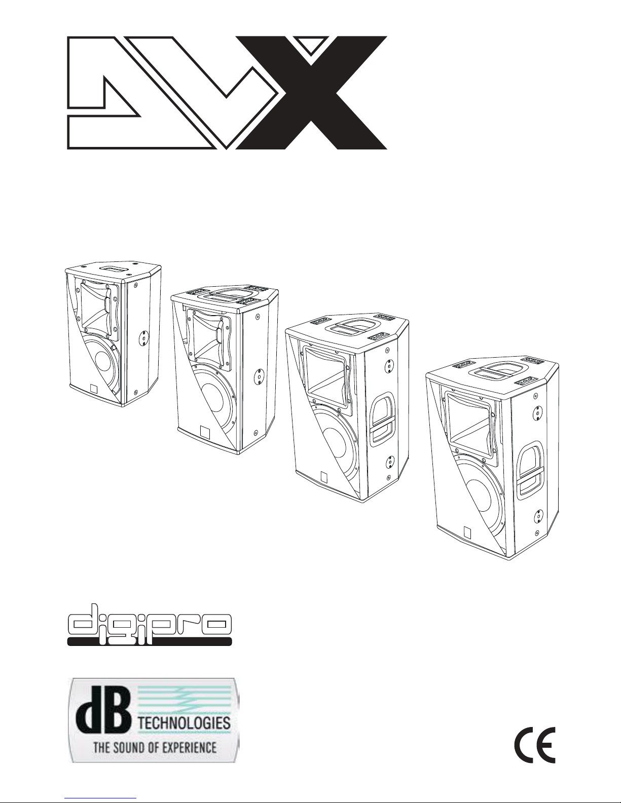
DXV D8 HP
The D8 HP bi-amped active speaker is equipped with a
®
DIGIPRO amplifier delivering 800W.
D8 HP is a bi-amped speaker features a woofer 8” (voice coil
2”) and a compression driver 1” (voice coil 1.4”) on a 90°x70°
aluminium CD- horn.
The speaker’s horizontal directivity is 90° by default factory
setting.
The speaker is made of 12mm birch ply wood, the one top
handle housing, the 6 flytracks, the 10 M8 threads and the 2
flypins located on the sides and the back of the speaker are
enabling easy transport and installation.
The speaker has been designed to be used also as stage
monitor (45° angle). By rotating the horn you can maintain the
same coverage angle also when the speaker is used as
monitor.
In the bottom of the box there is a standard pole mount cup
(D36mm) made of aluminium.
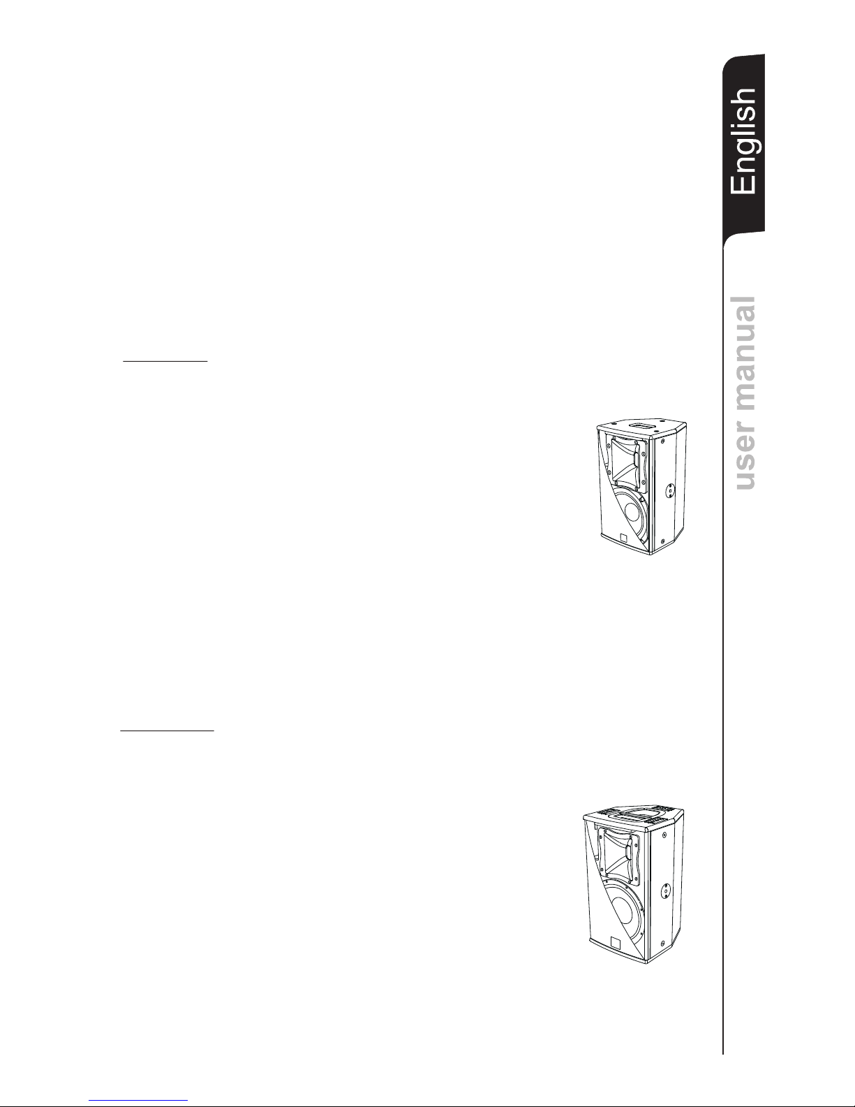
DVX D10 HP
The D10 HP bi-amped active speaker is equipped with a
®
DIGIPRO G2 amplifier delivering 1200W.
D10 HP is a bi-amped active speaker features a woofer 10”
(voice coil 2,5”) and a compression driver 1” (voice coil 1,75”)
on a 90°x70° aluminium CD- horn.
The speakers’ horizontal directivity is 90° by default factory
setting.
The speaker is made of 12mm birch ply wood, the one top
handle in aluminum , the 6 flytracks, the 6 M10 threads and
the 2 flypins located on the sides and the back of the speaker
are enabling easy transport and installation.
The speaker has been designed to be used also as stage
monitor (45° angle). By rotating the horn you can maintain the
same coverage angle also when the speaker is used as
monitor.
In the bottom of the box there is a standard pole mount cup
(D36mm) made of aluminium.
Page 3
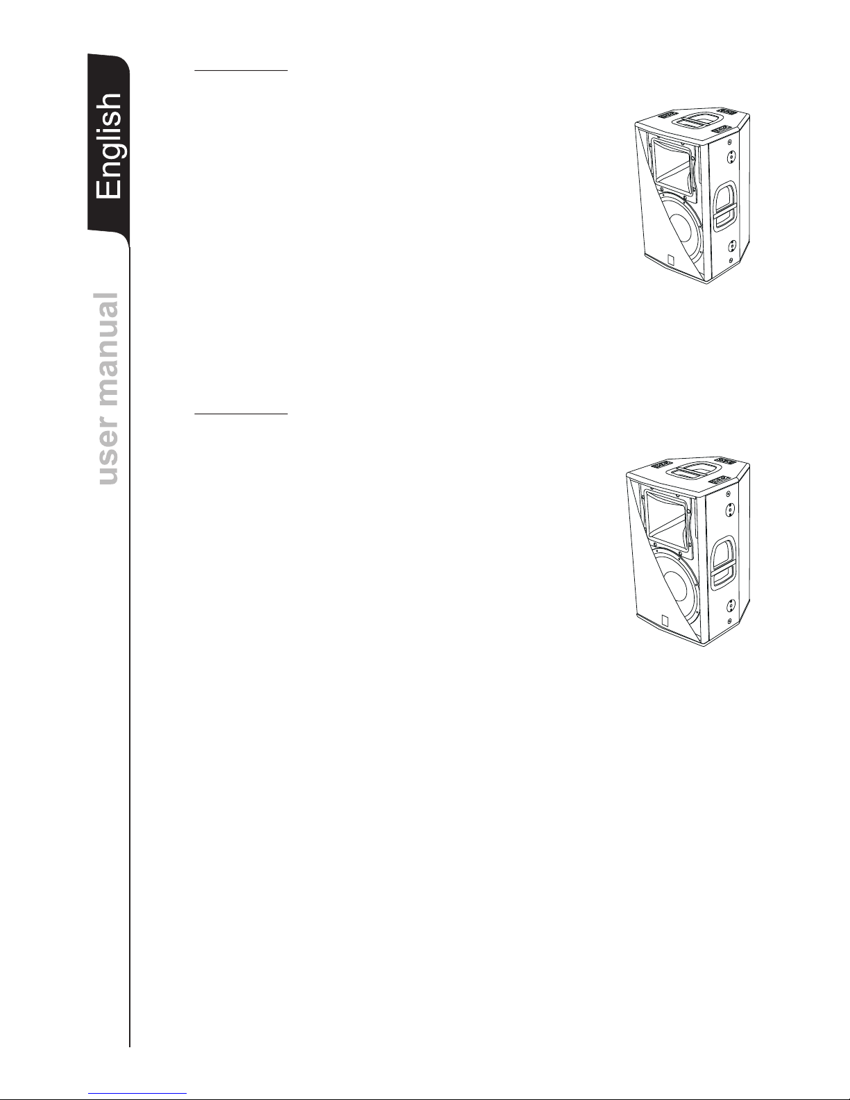
DVX D12 HP
The D12 HP bi-amped active speaker is equipped with a
®
DIGIPRO G2 amplifier delivering 1400W .
The D12 HP is a bi-amped active speaker features 12” (voice
coil 3”) woofer and a 1.4” (voice coil 3”) compression driver
installed on a 60°x40° aluminium CD- horn.
The speaker’s horizontal directivity is 60° by default factory
setting.
The speaker is made of 15mm birch ply wood, the 3 handles,
the 6 flytracks, the 6 M10 threads and the 4 flypins located on
the sides and the back of the speaker are enabling easy
transport and installation.
The speaker has been designed to be used also as stage
monitor (45° angle). By rotating the horn you can maintain the
same coverage angle also when the speaker is used as
monitor.
In the bottom of the box there is a standard pole mount cup
(D36mm) made of aluminium.
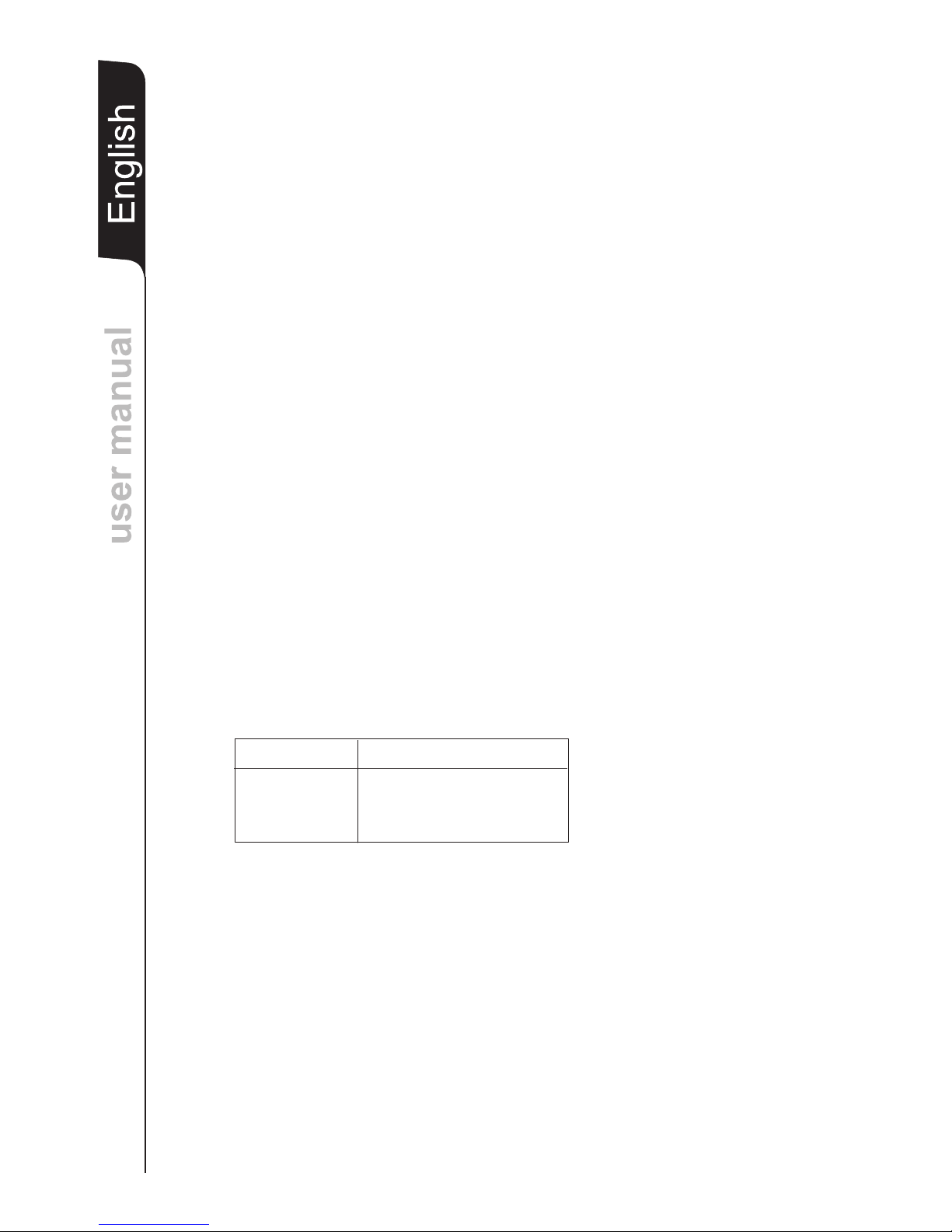
DVX D15 HP
The D15 HP bi-amped active speaker is equipped with a
®
DIGIPRO G2 amplifier delivering 1400W
The D15 HP is a bi-amped active speaker features a 15” (voice
coil 3”) woofer and a 1.4” (voice coil 3”) compression driver
installed on a 60°x40° aluminium CD- horn.
The speaker’s horizontal directivity is 60° by default factory
setting.
The speaker is made of 15mm birch ply wood, the 3 handles,
the 6 flytracks, the 6 M10 threads and the 4 flypins located on
the sides and the back of the speaker are enabling easy
transport and installation.
The speaker has been designed to be used also as stage
monitor (45° angle). By rotating the horn you can maintain the
same coverage angle also when the speaker is used as
monitor.
In the bottom of the box there is a standard pole mount cup
(D36mm) made of aluminium.
user manualuser manual
EnglishEnglishEnglish
9
COMMANDS AND FUNCTIONS (reference page29)
1) “BALANCED INPUT” CONNECTOR
These balanced inputs can be used to connect balanced or unbalanced microphones
or audio sources at line level (0dB) (eg. preamplifier, mixer, recorder, CD player,
musical instrument, ...).
2) “LINK” - “INPUT-LINK” CONNECTORS
The balanced connector is connected in and can be used to send
the audio signal to other amplified speakers, recorders or supplementary amplifiers.
3) “LIMITER” INDICATOR LIGHT
This indicator shows red to indicate that the internal limiter circuit has tripped.
This prevents amplifier distortion and protects the speakers against overloads.
4) “SIGNAL” INDICATOR LIGHT
This indicator shows green to indicate the presence of the audio signal (at a level of 20dB).
parallel with input (1)
CONNECTIONS
Page 4

EnglishEnglishEnglish
user manualuser manual
10
5) “READY” INDICATOR LIGHT
This indicator shows green to indicate that the main power voltage is correct.
The LED shows green normal operating conditions
6) “SENSITIVITY” INPUT SENSITIVITY CONTROL
This control adjusts the sensitivity of the signal amplifier input.
This control does not affect the “LINK” - “INPUT - LINK” output level.
7) “MODE” SWITCH
This two-way switch allows to choose between two different system presets.
The “FULL RANGE” position allows linear response of the speaker, which is mainly
suitable for the “live” application.
8) “INPUT SENS” SWITCH
Position the switch in LINE to use a line level source (0 dB) or MIC to use a
microphone.
9) FUSE CARRIER “FUSE”
Mains protection fuse housing. The fuse specifications are found in the data plate of
the apparatus. In case of failure to replace it with one of the same type and value
specified.
10) "MAINS INPUT" POWER SOCKET
To connecting the power cable provided.
The connector used for mains connection is a POWER CON® (blue) socket
11) “MAINS LINK” OUTPUT POWER SOCKET
To linking the mains power. The output is connected in parallel with input (10) and
can be used to power another active speaker.
The connector is a POWER CON® (grey) socket.
The “STAGE MONITOR” position makes its use easier in the monitor application by
limiting the low frequencies, which are emphasized by the floor.
CONNECTIONS
Connecting to the mains supply
Each active speaker features its own power cable. Connection is done by a Neutrik
POWER CON® (blue) model which permits easy and fast connection to the speaker as
well as being an excellent locking system.
The same connector serves as a switch to turn ON and OFF the active loudspeaker by
turning the connector to the left (OFF) or right (ON).
The active speaker must be connected to a power supply able to deliver the maximum
required power.
Main power supply linking
On the rear of the speaker, a Neutrik POWER CON® connector (grey) offers linking the
mains power supply.
This socket links the power supply to another speaker, thereby reducing the direct
connections to the mains. Maximum amplifier input power is shown on the amplifier panel.
The maximum number of speakers connected together varies of max input power and of
the maximum allowed current of the first power socket.
Page 5
user manualuser manual
EnglishEnglishEnglish
11
CHARACTERISTICS AND PROTECTION
The speakers’s components in the box are protected by 1,2mm DVX D8HP and D10 HP
DVX D12HP and D15 HP metal steel grille covered by foam on backside.
Front Grille
()
or 1,5mm ( )
Cooling
Thermal control is provided by the internal microprocessor which, by means of two sensors,
controls the temperature of the amplifier and of the power supply, avoiding overheating by
limiting the overall volume.
In case of overheating (> 80 degrees) the volume decreases proportionally to the
temperature increase, making the change unnoticeable.
The correct volume and all the functions are automatically restored when standard
operating temperatures are reached.
Switch on
The amplifiers are equipped with a microprocessor to control the DSP and the amplifier.
The correct switch on of the amplifier is ensured by an initialization procedure; during this
test stage the LEDs ( LIMITER , SIGNAL AND READY ), located on the amplifier
module, remain off for approx. 2 sec.
At the end of the switch on procedure, on the amplifier module, the READY green LED
only remains steadily on.
In case of severe failure of the speaker, on the amplifier module, the LIMITER red LED
flashes. The speaker switches to “mute”.
Failure indications and safeties
The microprocessor is able to signal three different kinds of failure by flashing the “LIMTER”
red LED on the amplifier panel before the lighting up of the “READY” green LED. The three
types of failure are:
1) WARNING: a non severe error or auto-ripristinate malfunction is detected and the
performance of the speaker is not limited
2) LIMITATION: an error is detected and the performance of the speaker is limited (the
sound level is reduced by 3dB).
This does not affect the operation of the speaker since it continues to operate.
However, it is necessary to call the service centre to solve the issue.
“”“” “”
“”
“”
3) FAILURE: a severe malfunction is detected. The speaker switches to “mute”.
Flashing Indication
1 or 2 Warning
3 or 4 Limitation
from 5 to 8 Failure
In case of failure, the “READY” green LED remains off.
Perform the checks listed below:
- Check if the speaker is properly connected to the power supply.
- Make sure that the power supply is of correct voltage.
- Check that the amplifier is not overheated.
- Disconnect the speaker from the mains power supply, wait for a few minutes and
connect it again.
If this error signaling remains active contact the authorized service center to resolve the
problem.
ROTATING HORN
LOUDSPEAKER INSTALLATION
Page 6

EnglishEnglishEnglish
user manualuser manual
12
WARNING
Never use the handles to hang the speaker!
ROTATING HORN
When used horizontally, the loudspeaker allow to maintain the same coverage angle by
featuring a rotating horn.
The speakers are always supplied by the manufacturer with the horn positioned horizontal
at 90°by default for D8 HP and D10 HP speakers and with the horn positioned horizontal at
60°by default for D12HP and D15 HP speakers.
If you wish to change the coverage angle (FIG.A page 33, 34):
- unscrew the fixing screws of the grille
- remove the front protective grille by slightly pressing on one side and taking the grille
off the recessed slots
- unscrew the eight fixing screws of the horn
- rotate the horn in the desired position (the horn should never be removed from the
driver!)
- tighten the fixing screws of the horn
- put the grille back in the recessed slots and tighten the screws of the grille.
LOUDSPEAKER INSTALLATION
WARNING
Make sure that the loudspeaker is securely installed in a stable position to avoid any
injuries or damages to persons or property.
For safety reasons do not place one loudspeaker on top of another without proper
fastening systems. Before hanging the loudspeaker check all the components for
damages, deformations, missing or damaged parts that may compromise safety during
installation.
If you use the loudspeakers outdoors avoid places that are exposed to bad weather.
The loudspeaker has the following mounting options:
- bookshelf (Fig. 1 page 35)
- floor (monitor) (Fig.2 page 35)
- on speaker stands (Fig.3 page 36)
- suspended with eyebolts (Fig.4 page 36,37) or flytracks - excluded DVX D8HP (Fig.5 page 37)
- brackets supplied by the manufacturer
EXACT!
WRONG! EXACT!
WARNING only for DVX D8HP
To hang the loudspeaker use only one eyebolt for each hanging point
The hanging points are of M8 threads.
Do not unscrew both bolts recessed in the housing!
Page 7

user manualuser manual
EnglishEnglishEnglish
13
DVX D8 HP
DVX D12 HP - DVX D15 HP
DVX D10 HP
Handle
Flypin
M10
M10
M10
M10
Handle
Handle
Flypin
Flytrack
Flytrack
M8
M8
M8
M8
M8
Flypin
Flypin
M10
Flytrack
Flytrack
Flypin
Flypin
M10
M10
M10
HandleHandle
EMI CLASSIFICATION
According to the standards EN 55103 this equipment is designed and suitable to operate in E3
(or lower E2, E1) Electromagnetic environments.
Page 8

EnglishEnglishEnglish
user manualuser manual
14
TECHNICAL SPECIFICATIONS
DVX D8HP DVX D10HP DVX D12HP DVX D15HP
System Active Bi-Amp Active Bi-Amp Active Bi-Amp Active Bi-Amp
Type of amplifier Class D Class D Class D Class D
Power 400W RMS/800W PEAK 600W RMS/1200W PEAK 700W RMS/1400W PEAK 700W RMS/1400W PEAK
Frequency response 100 -19000Hz (-3dB) 85 -19000Hz (-3dB) 68-19000Hz (-3dB) 57-19000Hz (-3dB)
75-20000Hz (-10dB) 70-20000Hz (-10dB) 55-20000Hz (-10dB) 49-20000Hz (-10dB)
Crossover 1850Hz - 24dB/oct 1650Hz - 24dB/oct 1350Hz - 24dB/oct 1320Hz - 24dB/oct
Sound pressure (max SPL) 125dB 127dB 131dB 132dB
Components 1x8” woofer - 2” voice coil 1x10” woofer - 2.5” voice coil 1x12” woofer - 3” voice coil 1x15” woofer - 3” voice coil
1x1”compression driver - 1.4” voice coil 1x1”compression driver - 1.75” voice coil 1x1.4”compression driver - 3” voice coil 1x1.4”compression driver - 3” voice coil
Dispersion 90°x70° 90°x70° 60°x40° 60°x40°
Input sensitivity -40dBu/-3dBu (MIC/LINE) -40dBu/-3dBu (MIC/LINE) -40dBu/-3dBu (MIC/LINE) -40dBu/-3dBu (MIC/LINE)
Impedance input 2K2ohm/ 20Kohm (MIC/LINE) 2K2ohm/ 20Kohm (MIC/LINE) 2K2ohm/ 20Kohm (MIC/LINE) 2K2ohm/ 20Kohm (MIC/LINE)
Power supply 110-220V 50-60Hz 110-220V 50-60Hz 110-220V 50-60Hz 110-220V 50-60Hz
220-240V 50-60Hz 220-240V 50-60Hz 220-240V 50-60Hz 220-240V 50-60Hz
Inrush current 18,7A 22,4A 22,4A 22,4A
Housing shape Trapezoidal Trapezoidal Trapezoidal Trapezoidal
Colour Black Black Black Black
Dimension (WxHxD) 250x425x260mm 290x510x310mm 370x625x395mm 430x690x450mm
Weight 9,7Kg 15,8Kg 27,5Kg 30,3Kg
Flying support ----------- 6 x flytrack 6 x flytrack 6 x flytrack
10 x M8 6 x M10 6 x M10 6 x M10
2 x flypin 2 x flypin 4 x flypin 4 x flypin
Pole mount cup D36mm (aluminium) D36mm (aluminium) D36mm (aluminium) D36mm (aluminium)
Handle ----------- ----------- 2 aluminium - one per side 2 aluminium - one per side
1 housing - top side 1 aluminium - top side 1 aluminium - top side 1 aluminium - top side
Rotating horn Ye s Yes Ye s Ye s
Page 9

29
DVX D8 HP - DVX D10 HP - DVX D12 HP - DVX D15 HPDVX D8 HP - DVX D10 HP - DVX D12 HP - DVX D15 HP
PUSH
DD
MODE
READY
SIGNAL
LIMITER
8
0dB
+4dB
-3dB
FULL-RANGE
STAGE MONITOR
BALANCED
INPUTS
LINK
INPUT / LINKINPUT / LINK
SENSITIVITY
MIC
INPUT
SENS
INPUT
SENS
LINELINE
DIGITAL ACTIVE SPEAKER
1
8
7
6
5
4
3
11
10
9
2
SCHEMA A BLOCCHI - BLOCK DIAGRAM
BLOCKSCHALTBILD - SCHEMAS FONCTIONNELS
BALANCED
INPUTS
LINK
MAINS INPUT
MAINS LINK
G2G2
REPLACE FUSE WITH SAME RATING
Digital Power
Punta
Funzionamento sbilanciato con
connettore jack 1/4” (6,3mm)
Funzionamento sbilanciato con
connettore XLR
Ingresso
XLR - maschio
Tip
Unbalanced use of stereo 1/4” jack plug
Unbalanced use with XLR connectors
XLR - male
COLLEGAMENTI CONNECTIONS
ANSCHL BRANCHEMENTS
Page 10

30
SCHEMA A BLOCCHI - BLOCK DIAGRAM
BLOCKSCHALTBILD - SCHEMAS FONCTIONNELS
READYLIMITER
Switching Mode
Power Supply
SMPS
SIGNAL
SENSITIVITY
Class D
®
DIGIPRO G2
DSP
Digital Signal Processing
MICROPROCESSOR
Class D
MODE
WOOFER
DRIVER
BALANCED
INPUTS
LINK
INPUT
SENS
MAINS INPUT
FUSE
L
N
MAINS LINK
L
N
Anello
Gambo
Punta = Positivo/Caldo/Fase +VE
Anello = Negativo/Freddo/Fase -VE
Punta
Gambo
Punta = Segnale
Gambo=Schemo/Massa/Terra
Funzionamento sbilanciato con
connettore jack 1/4” (6,3mm)
11
22
33
Ingresso
XLR - maschio
Pin 3 =Negativo/Freddo/Fase -VE
11
22
33
Funzionamento sbilanciato con
connettore XLR
Ingresso
XLR - maschio
Pin 2 = Positivo/Caldo/Fase +VE
Pin 1 =Schermo/Terra/Massa
Pin 3 = Connesso al Pin 1
Funzionamento bilanciato con
connettore jack 1/4” (6,3mm)
Gambo=Schemo/Massa/Terra
Punta
Funzionamento bilanciato con
connettore XLR
Pin 2 = Positivo/Caldo/Fase +VE
Pin 1 =Schermo/Terra/Massa
Tip = Positive/Hot/+VE Phase
Balanced use of stereo 1/4” jack plug
Tip
Sleeve
Tip = Signal
Sleeve=Screen/Ground/Earth
Unbalanced use of stereo 1/4” jack plug
Balanced use with XLR connectors
Input
XLR - male
Pin 2 = Positive/Hot/+VE Phase
Pin 3 =Negative/Cold/-VE Phase
Pin 1 =Screen/Ground/Earth
Unbalanced use with XLR connectors
Input
XLR - male
Pin 2 = Positive/Hot/+VE Phase
Pin 1 =Screen/Ground/Earth
Pin 3 = Link to Pin 1
Ring=Negative/Cold/-VE Phase
Sleeve=Screen/Ground/Earth
Sleeve
Ring
Tip
COLLEGAMENTI CONNECTIONS
ANSCHL BRANCHEMENTS
-
ÜSSE -
Page 11

DIMENSIONI - DIMENSIONS
ABMESSUNGEN - DIMENSIONS
260260
310310 290290
510510
425425
45°45°
45°45°
DVX D8 HPDVX D8 HP
DVX D10 HPDVX D10 HP
250250
31
DIMENSIONI - DIMENSIONS
ABMESSUNGEN - DIMENSIONS
Page 12

32
395395
370370
450450 430430
690690
625625
45°45°
45°45°
DVX D12 HPDVX D12 HP
DVX D15 HPDVX D15 HP
DIMENSIONI - DIMENSIONS
ABMESSUNGEN - DIMENSIONS
Page 13

ANGOLO DI COPERTURA TROMBA / HORN ANGLE COVERED
HOCHTONHORN ABSTRAHLWINKEL / ANGLE DE COUVERTURE COTE
90°
70°
Utilizzo a pavimento (monitor) con tromba ruotata
Floor use (monitor) with rotated horn.
Verwendung auf dem Boden (monitor) mit gedrehtem Horn.
Utilisation au sol (écran) avec cone tourné
Fig. A
90°
70°
33
90°
70°
Utilizzo a pavimento (monitor) con tromba ruotata
Floor use (monitor) with rotated horn.
Verwendung auf dem Boden (monitor) mit gedrehtem Horn.
Utilisation au sol (écran) avec cone tourné
DVX D8 HP
DVX D10 HP
DVX D8 HP
DVX D10 HP
Page 14

34
ANGOLO DI COPERTURA TROMBA / HORN ANGLE COVERED
HOCHTONHORN ABSTRAHLWINKEL / ANGLE DE COUVERTURE COTE
60°
40°
Utilizzo a pavimento (monitor) con tromba ruotata
Floor use (monitor) with rotated horn.
Verwendung auf dem Boden (monitor) mit gedrehtem Horn.
Utilisation au sol (écran) avec cone tourné
Fig. A
60°
40°
60°
40°
DVX D12 HP
DVX D15 HP
DVX D12 HP
DVX D15 HP
Page 15

35
UTILIZZO IN APPOGGIO
SUPPORTED USE
ANWENDUNG
UTILISATION EN APPUI
Fig. 1
Fig. 2
UTILIZZO A PAVIMENTO (MONITOR)
FLOOR USE (MONITOR)
VERWENDUNG AUF DEM BODEN (MONITOR)
UTILISATION AU SOL (ÉCRAN)
Nota: E’ possibile montare 4 piedi in gomma
sul fianco per utilizzo in appoggio (in dotazione)
Note: It is possible to mount 4 rubber feet on the
side for bookshelf use (provided)
Anmerkung: Zur Verwendung als Boden-Monitor
können die 4 beiliegende Gummifüße montiert werden.
Note: Il est possible de monter quatre pieds caoutchouc
sur le coté puor une utilisation en appui (en dotation)
SUPPORTO PIANTANA STANDARD (D36M)
STANDARD STAND (D36MM)
STANDARD-HOCHSTÄNDERFLANSCH (D36MM)
SUPPORT STANDARD (D36MM)
APPENDIBILITA GOLFARI
SUSPENDABLE WITH EYEBOLTS
MAN KANN DEN LAUTSPRECHER MIT RINGSCHRAUBEN AUFHÄNGEN
POSSIBILITÉ DE SUSPENSION AVEC ANNEAUX
SOLO DVX D12 HP - D15 HP
ONLY DVX D12 HP - D15 HP
NUR DVX D12 HP- D15 HP
SEULEMENT DVX D12 HP- D15 HP
Il codice include solo i golfari.
The code including eyebolts only.
Contattare dB Technologies per gli accessori da utilizzare a corredo.
Si declina ogni responsabilità da un utilizzo inappropriato degli accessori o di dispositivi
aggiuntivi non idonei allo scopo.
Contact dB Technologies for accessories to be used with speakers.
Will not accept any responsibilty when inappropriate accessories or not suitable additional
devices are used.
Kontaktieren sie dBTechnologies für passendes Lautsprecherzubehör.
Falls unpassendes Zubehör verwendet wird, wird jegliche Haftung ausgeschlossen.
Contact dBTechnologies pour les accessoires à utiliser avec la machine.
N'accepterons pas toutes les responsabilités lorsque des accessoires inappropriés ou ne
conviennent pas à des dispositifs supplémentaires sont utilisés.
ISTRUZIONI DI SICUREZZA PER ACCESSORI
ZUBEHÖR
INSTRUCTIONS DE SÉCURITÉ
SAFETY INSTRUCTIONS FOR ACCESSORIES
SICHERHEITSHINWEISE
POUR LES ACCESSOIRES
Fig. 4
Page 16

36
Fig. 3
SUPPORTO PIANTANA STANDARD (D36M)
STANDARD STAND (D36MM)
STANDARD-HOCHSTÄNDERFLANSCH (D36MM)
SUPPORT STANDARD (D36MM)
APPENDIBILITA GOLFARI
SUSPENDABLE WITH EYEBOLTS
MAN KANN DEN LAUTSPRECHER MIT RINGSCHRAUBEN AUFHÄNGEN
POSSIBILITÉ DE SUSPENSION AVEC ANNEAUX
' TRAMITE
Opzione codice/Optional code:
TE M8
Il codice include solo i golfari.
The code including eyebolts only.
DVX D8HP
Fig. 4
Page 17

Fig. 5
APPENDIBILITA FLYTRACKS
SUSPENDABLE WITH FLYTRACKS
MAN KANN DEN LAUTSPRECHER MITTELS FLUGSCHIENEN AUFHÄNGEN
POSSIBILITÉ DE SUSPENSION AVEC FLYTRACK
' TRAMITE
APPENDIBILITA GOLFARI
SUSPENDABLE WITH EYEBOLTS
MAN KANN DEN LAUTSPRECHER MIT RINGSCHRAUBEN AUFHÄNGEN
POSSIBILITÉ DE SUSPENSION AVEC ANNEAUX
' TRAMITE
Fig. 4
Opzione codice/Optional code:
TE M10
Il codice include solo i golfari.
The code including eyebolts only.
DVX D10HP
DVX D12HP
DVX D15HP
DVX D10HP
DVX D12HP
DVX D15HP
37
Kit completo
Complete kit
Page 18

38
Staffa a muro/supporto piantana
Wall bracket/stand adaptor
opzione DTF 12 --> DXV D12 HP
opzione DTF 15 --> DXV D15 HP
Gli accessori per il fissaggio della staffa
non sono forniti in dotazione
The fixing accessory for wall bracket are
not suppling with the kit
Per supporto piantana
Stand adaptor
Fissaggio su strutture a traliccio
Fixing on truss structures
Per fissaggio a muro
For wall brackets
Kit completo
Complete kit
Page 19

39
Kit completo
Complete kit
Staffa supporto piantana
Stand adaptor
opzione DTF 8 --> DXV D8 HP
opzione DTF 10 --> DXV D10 HP
Per supporto piantana
Stand adaptor
Fissaggio su strutture a traliccio
Fixing on truss structures
Page 20

A.E.B. INDUSTRIALE s.r.l.
Via Brodolini, 8 - 40056 Crespellano (Bo) - ITALIA
Tel. + 39 051 969870 - Fax. + 39 051 969725
Internet: www.dbtechnologies.com
E-mail: info@dbtechnologies-aeb.com
D8 HPD8 HP
 Loading...