

Page 1
SS
22
00
ACTIVE SUBWOOFER
A.E.B. INDUSTRIALE s.r.l.
Via Brodolini, 8 - 40056 Crespellano (Bo) - ITALIA
Tel. + 39 051 969870 - Fax. + 39 051 969725
Internet: www.dbtechnologies.com
E-mail: info@dbtechnologies-aeb.com
MANUALE d’USO - Sezione 1
USER MANUAL - Section 1
BEDIENUNGSANLEITUNG - Abschnitt 1
CARACTERISTIQUES TECHNIQUES - Section 1
Made in Italy
COD. 420120169 Rev 4.0
RR
digital power
Page 2

COMANDI E FUNZIONI
E’ possibile utilizzare questo circuito per la realizzazione di sistemi in configurazione
cardioidi. La configurazione cardioide permette una notevole attenuazione delle
basse frequenze emesse dalla parte posteriore dei subwoofer, mantenendo
inalterata l'emissione sonora frontale.
Tale configurazione prevede un minimo di 3 subwoofer (due con emissione frontale
e uno con emissione posteriore equipaggiato con modulo SDD).
ItalianoItalianoItaliano
ItalianoItalianoItaliano
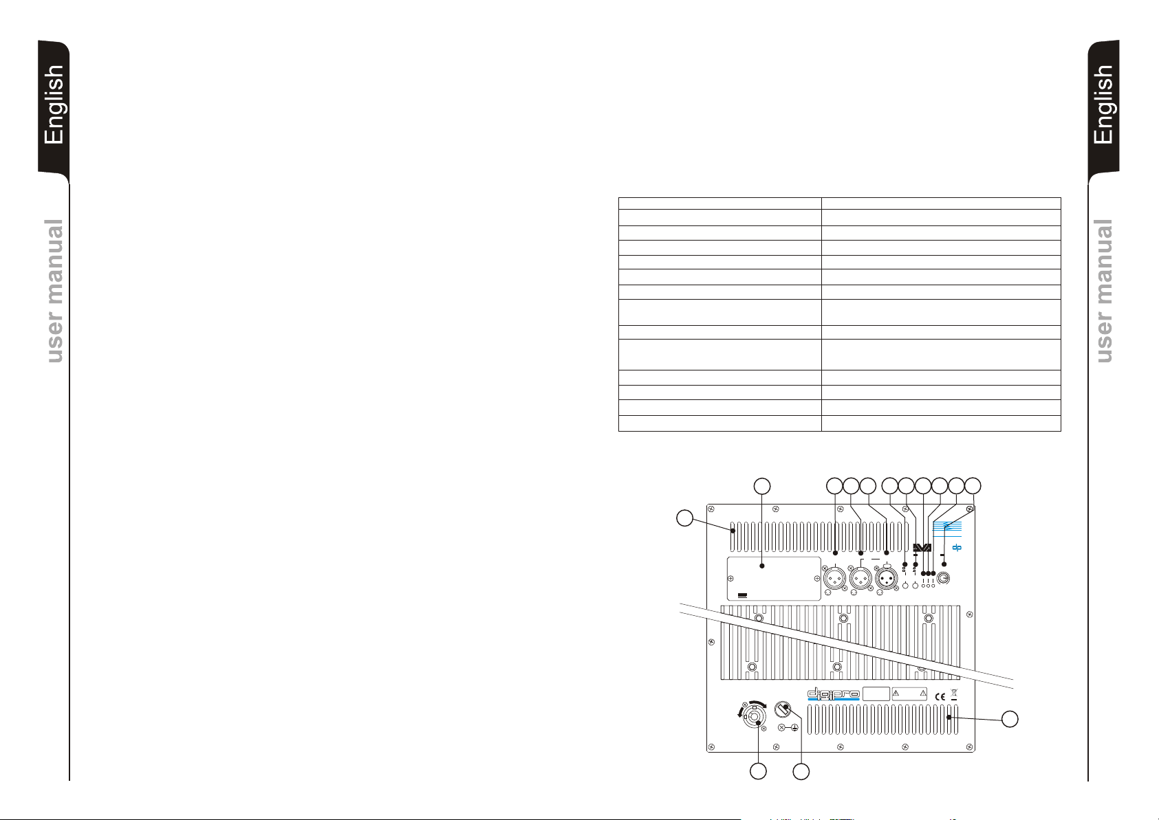
1) PORTA FUSIBILE “MAINS FUSE”
Alloggio per fusibile di rete.
2) PRESA DI ALIMENTAZIONE “FULL RANGE MAINS INPUT”
Consente la connessione del cavo di alimentazione fornito in dotazione.
Il connettore utilizzato per il collegamento alla rete è un POWER CON® (blu)
3) GRIGLIE DI RAFFREDDAMENTO
Queste griglie permettono il raffreddamento dell’amplificatore durante il
CLASSIFICAZIONE EMI
In accordo alle normative EN 55103, l'apparato è progettato e idoneo all'utilizzo in ambiente
Elettromagnetico E5.
funzionamento. Non ostruire gli accessi e pulire le griglie quando necessita per
Manuale d’usoManuale d’uso
garantire il corretto circolo dell’aria.
4) CONNETTORE DI INGRESSO " BALANCED MAIN INPUT”
Ingresso bilanciato a livello linea (0 dBu).
E’ in grado di accettare prese “XLR”.
5) CONNETTORE DI USCITA "LINK”
Il connettore “XLR” connesso in parallelo con l’ingresso (4) può essere utilizzato per
inviare il segnale audio in ingresso ad un altro diffusore amplificato.
6) CONNETTORE DI USCITA ”BALANCED X-OVER OUTPUT”
Uscita bilanciata del crossover interno. Il segnale prelevato da questa uscita può
essere inviato a qualsiasi diffusore amplificato.
La frequenza di taglio è selezionabile tramite il selettore “SUB X-OVER” (7).
7) SELETTORE “SUB X-OVER”
Il selettore permette di modificare l’incrocio (frequenza di taglio o crossover) tra il
subwoofer ed il diffusore ad esso collegato, tramite l’uscita “BALANCED X-OVER
OUTPUT”.
L’incrocio è settabile a 90Hz oppure 120Hz con una pendenza di 24dB/oct.
La scelta del taglio è legata dal tipo di riproduzione sonora che si vuole ottenere.
8) SELETTORE “SUB PHASE”
Il selettore permette la rotazione di 180° del segnale audio riprodotto dal subwoofer.
DATI TECNICI
Sistema Attivo
Tipologia amplificatore Digitale - Classe D (DIGIPRO )
Potenza RMS 2000 W (1000 W + 1000 W)
Potenza musicale 4000 W
Risposta in frequenza +/-3dB
Crossover
Pressione sonora (SPL) 138 dB peak
Componenti 2 woofer 18” - 4” voice coil
Sensibilità ingresso nominale 0 dBu
Impedenza ingresso Bilanciato 20Kohm
Sbilanciato 10Kohm
Forma diffusore rettangolare
Dimensioni [LxHxP] 1100x720x580mm
Peso Neodimio 77Kg - Ceramico 84Kg
25-150Hz
90 - 120Hz (24dB/oct) selezionabile
Neodimio o Ceramico
Full-range con PFC, 100-240Vac, 50-60HzAlimentazione
®
Manuale d’usoManuale d’uso
Tale rotazione di fase facilita l’ottimizzazione della riproduzione delle frequenze
basse anche nelle situazioni di installazioni più difficili. Completata l’installazione,
riprodurre un brano musicale ed agire sul selettore per ottenere la migliore resa
acustica delle basse frequenze
7
4
8
9) INDICATORE LUMINOSO “ON”
13
5
6
9
101211
L’indicatore luminoso “ON” s’illumina di colore verde per indicare l’accensione e il
corretto funzionamento dell’amplificatore.
10) INDICATORE LUMINOSO “SGN”
Questo indicatore s'illumina di colore verde per indicare la presenza del segnale (ad
un livello di -20dB).
11) INDICATORE LUMINOSO “LIM”
Questo indicatore s’illumina di colore rosso per indicare l'intervento del circuito
limitatore interno, il quale evita la distorsione dell'amplificatore e protegge gli
altoparlanti contro sovraccarichi.
3
TECHNOLOGIESTECHNOLOGIES
dd
BB
SS
00
22
SS
DD
SUBWOOFER DIGITAL DELAY
OPTIONAL CARD
TECHNOLOGIESTECHNOLOGIES
d
B
BALANCED
LINK
X-OVER
DD
OUTPUT
1 = GND
1
1
2
2
2 = HOT
3
3
3 = COLD
BALANCED
MAIN INPUT
12
3
NEODYMIUM CERAMIC
PUSH
SUB-WOOFER
0°
120Hz
LEVEL
90Hz
180°
+10
LIM
ON SGN
SUB
SUB
XOVER
+4
PHASE
0dB
8
Si illumina anche all’accesione dell’amplificatore per alcuni secondi.
12) CONTROLLO SENSIBILITA’ IN INGRESSO “SUB-WOOFER LEVEL”
Questo controllo regola la sensibilità del segnale in ingresso all’amplificatore.
Tale controllo non influisce sul livello dell’uscita “LINK” e “BALANCED X-OVER
OUTPUT”
13) OPZIONE DIGITAL DELAY “SDD - SUBWOOFER DIGITAL DELAY”
Il diffusore DVA S20dp può essere equipaggiato con un circuito di delay (SDD -
SUBWOOFER DIGITAL DELAY) che permette di ritardare il segnale audio riprodotto
dal subwoofer.
Questo circuito permette l’allineamento acustico tra line array e sub compensando le
FULL RANGE MAINS INPUT
100-240V~ 50-60Hz
2500W MAX
O
N
F
F
O
ACTIVE P.F.C.
MAINS FUSE
220-240V~ (T10A 250V)
100-120V~ (T20A 250V)
digital power
“CAUTION”
TO PREVENT ELECTRICAL SHOCK
DO NOT REMOVE COVER
“AVIS”
RISQUE DE CHOCH ELECTRIQUE
SERIAL N.
NE PAS OUVRIR
3
diverse posizioni. Il circuito include anche una uscita bilanciata “XLR” per rilanciare il
segnale audio ritardato ad altri subwoofer; utilizzando un solo circuito di delay è
1
possibile ritardare contemporaneamente più subwoofer.
2
1
2
Page 3
CONTROLS AND FUNCTIONS
1) "MAINS FUSE" FUSE CARRIER
Mains fuse housing.
the rear side of the subs, without changing the direct radiated signal on the front
side.
This configuration needs at least 3 subwoofers (two with front radiation and one with
rear radiation equipped with SDD module). See appendix for more details.
2) “FULL RANGE MAINS INPUT" POWER SOCKET
EnglishEnglishEnglish
For connecting the power cable provided.
The connector used for mains connection is a POWER CON® (blue)
3) COOLING GRILLE
These grilles permit cooling the amplifier during operation.
EMI CLASSIFICATION
According to the standards EN 55103 this equipment is designed and suitable to operate in
E5 Electromagnetic environment.
EnglishEnglishEnglish
Do not block accesses and clean the grilles whenever necessary to ensure correct
air circulation.
4) " BALANCED MAIN INPUT” INPUT CONNECTOR
Balanced input at line level (0 dBu).
It is able to accept “XLR” sockets.
5) "LINK” OUTPUT CONNECTOR
The “XLR” connector connected in parallel with input (4) can be used to send the
input audio signal to another amplified speaker.
6) ”BALANCED X-OVER OUTPUT” OUTPUT CONNECTOR
Internal crossover balanced output. The signal from this output can be sent to any
other amplified speaker.
The crossover frequency can be selected by means of the “SUB X-OVER” switch
(7).
7) “SUB X-OVER” SWITCH
user manualuser manual
This switch permits selection of crossover frequency between the sub woofer and
the speakers connected to the ”BALANCED X-OVER OUTPUT” connector.
The crossing frequency is selected to 90Hz or 120Hz with a slope of 24dB/oct.
The frequency choice depends to the sound reproduction desire.
8) “SUB PHASE ” SWITCH
This switch permits 180° rotation of the audio signal reproduced by subwoofer.
Rotation makes for easier optimization of low-frequency reproduction even in the
most difficult installation situations. After completing installation, reproduce a piece
TECHNICAL SPECIFICATION
System Active
Type of amplifier Digital - Class D (DIGIPRO )
RMS power 2000 W (1000 W + 1000 W)
Musical power 4000 W
Frequency responce +/-3dB
Crossover 90 - 120Hz (24dB/oct) selecting
Sound pressure (SPL) 138dB peak
Woofer 2 x woofer 18”- 4” voice coil
Input sensitivity nominal 0 dBu
Impedance input Balanced 20Kohm
Unbalanced 10Kohm
Speaker shape rectangular
Dimension [WxHxD] 1100x720x580mm
Weight Neodymium 77Kg - Ceramic 84Kg
25-150Hz
Neodymium or Ceramic
Full-range with PFC, 100-240Vac, 50-60HzPower supply
®
user manualuser manual
of music and adjust the switch to obtain the best low-frequency sound.
9) “ON” INDICATOR LIGHT
7
4
8
The “ON” indicator light comes on green to indicate the amplifier is switched on and it
13
5
6
9
101211
is working properly.
10) “SGN” INDICATOR LIGHT
This indicator comes on green to indicate the presence of the audio signal (at a level
of -20dB).
11) “LIM” INDICATOR LIGHT
This indicator comes on red to indicate that the internal limiter circuit has tripped.
This prevents amplifier distortion and protects the speakers against overloads.
It is lights for a few seconds during the switching on.
3
TECHNOLOGIESTECHNOLOGIES
dd
BB
SS
00
22
SS
DD
SUBWOOFER DIGITAL DELAY
OPTIONAL CARD
TECHNOLOGIESTECHNOLOGIES
d
B
BALANCED
LINK
X-OVER
DD
OUTPUT
1 = GND
1
1
2
2
2 = HOT
3
3
3 = COLD
BALANCED
MAIN INPUT
12
3
NEODYMIUM CERAMIC
PUSH
SUB-WOOFER
0°
120Hz
LEVEL
90Hz
180°
+10
LIM
ON SGN
SUB
SUB
XOVER
+4
PHASE
0dB
8
12) “SUB WOOFER LEVEL” INPUT SENSITIVITY CONTROL
This control regulates the sensitivity of the signal at amplifier input.
This control does not affect the “LINK” and “BALANCED X-OVER OUTPUT” output
levels
13) DIGITAL DELAY “SDD - SUBWOOFER DIGITAL DELAY” OPTION
The DVA loudspeaker can be equipped with a delay module (SDD SUBWOOFER DIGITAL DELAY) that allows to delay the sound signal reproduced
by the subwoofer.
by balancing the various positions.
The circuit also includes a balanced “XLR” output that sends the delayed audio
signal to other subwoofers. By using a single delay module it is possible to delay
S20dp
This circuit allows sound-alignment between line array and sub
FULL RANGE MAINS INPUT
100-240V~ 50-60Hz
2500W MAX
O
N
F
F
O
ACTIVE P.F.C.
MAINS FUSE
220-240V~ (T10A 250V)
100-120V~ (T20A 250V)
digital power
“CAUTION”
TO PREVENT ELECTRICAL SHOCK
DO NOT REMOVE COVER
“AVIS”
RISQUE DE CHOCH ELECTRIQUE
SERIAL N.
NE PAS OUVRIR
3
several subwoofers at the same time.
This module can also be used to create cardioid configuration systems. The cardioid
3
configuration provides a remarkable attenuation of the low frequencies radiated by
2
1
4
Page 4

BEDIENELEMENTE UND FUNKTIONEN
1) SICHERUNGSHALTER “MAINS FUSE”
Halter für die Netzsicherung.
2) ANSCHLUSSBUCHE “FULL RANGE MAINS INPUT”
Für den Anschluss des beiliegenden Netzkabels.
Für den Netzanschluss wird ein Stecker POWER CON® (blau) verwendet.
DeutschDeutschDeutsch
BedienungsanleitungBedienungsanleitung
3) LÜFTUNGSGITTER
Diese Gitter erlauben die Kühlung der Endstufe während des Betriebs. Die
Lüftungsöffnungen nicht abdecken und die Gitter nötigenfalls säubern, um die
ordnungsgemäße Luftzirkulation zu gewährleisten.
4) EINGANGSBUCHSE "BALANCED INPUT”
Symmetrischer Linepegel-Eingang (0 dBu).
Für XLR-Stecker
5) AUSGANGSBUCHSE "LINK”
Der parallel zum Eingang (4) angeschlossene XLR-Anschluss kann dazu verwendet
werden, das ankommende Audiosignal an einen anderen aktiven Lautsprecher
weiter zu leiten.
6) AUSGANGSBUCHSE ”X-OVER BALANCED OUTPUT”
Symmetrischer Ausgang der internen Frequenzweiche. Das Signal dieses
Ausgangs kann auch zu einem beliebigen sonstigen aktiven Lautsprecher
durchgeschleift werden. Die Trennfrequenz kann zwischen 90 und 120Hz mit dem
Schalter “SUB X-OVER” (7) umgeschalltet werden.
7) WAHLSCHALTER “SUB PHASE”
Mit diesem Schalter wird die Phase des S20dp Sub um 180° gedreht. Durch das
Drehen der Phase kann man die Wiedergabe der Bässe auch bei ungünstigen
akustischen Bedingungen in einfacher Weise optimieren. Nach Abschluss der
Installation ein Musikstück abspielen und ausprobieren, in welcher Schalterstellung
des Phasenschalters der Klang am besten ist.
8) WAHLSCHALTER “SUB X-OVER”
Mit diesem Schalter wird die Trennfrequenz zwischen dem S20dp Sub und den am
”BALANCED X-OVER OUTPUT” angeschlossenen Lautsprechern eingestellt. Die
Man kann dieses Modul für die Aufstellung auch von Konfigurationen
verwenden. Die Konfiguration ermöglicht eine erhebliche Dämpfung der
kardiode
tiefen Frequenzen, die über die Rückseite der Subwoofer abgestrahlt werden.Die
vordere akustische Abstrahlung bleibt dabei unverändert.
Für diese Konfiguration notwendig (zwei mit vorderer Abstrahlung
sind 3 Subwoofer
und einer mit hinterer Abstrahlung und mit SDD-Modul). Für weitere Details siehe
Anlagen.
EMV Einstufung
Entsprechend der Norm EN 55103 ist diese Gerät entwickelt um in E5 elektromagnetischen
Umgebungen zu arbeiten
TECHNISCHE EIGENSCHAFTEN
System Aktiv
Verstärker typ Digital - Class D (DIGIPRO )
RMS Leistung 2000 W (1000 W + 1000 W )
Musikleistung 4000 W
Frequenzgang +/-3dB
25-150Hz
Trennfrequenz 90 - 120Hz (24dB/Okt.)
Schalldruck (SPL) 138 dB peak
Lautsprecher 2 x woofer 18” - 4” voice coil
Neodymium - Ceramic
Eingangsempfindlichkeit 0 dBu
Impedanz Eingang Symmetrisch 20Kohm
Ünsymmetrisch 10Kohm
Netzspannung
Fullrange mit PFC, 100-240V (AC), 50-60Hz
Laufsprecherform rechteckig
Abmessungen [BxHxT] 1100x720x580mm
Gewicht Neodymium 77Kg - Ceramic 84Kg
kardiode
DeutschDeutschDeutsch
®
BedienungsanleitungBedienungsanleitung
Trennfrequenz kann zwischen 90 und 120Hz mit einer Flankensteilheit von
24dB/Okt. umgeschaltet werden. Die Wahl der Trennfrequenz hängt von den
7
4
8
akustischen Anforderrungen ab.
13
5
6
9
101211
9) LED “ON”
Diese LED leuchtet grün, wenn das Gerät an die richtige Netzspannung
angeschlossen ist. Während des normalen Betriebes leuchtet die LED grün..
10) LED “SGN”
Diese LED leuchtet grün, wenn das Audiosignal anliegt (mit einem Pegel von 20dB).
11) LED “LIM”
Diese rote LED leuchtet auf, um das Ansprechen des Limiters zu signalisieren,
welcher die Verzerrung des Verstärkers verhindert und die Lautsprecher gegen
3
TECHNOLOGIESTECHNOLOGIES
dd
BB
SS
00
22
SS
DD
SUBWOOFER DIGITAL DELAY
OPTIONAL CARD
TECHNOLOGIESTECHNOLOGIES
d
B
BALANCED
LINK
X-OVER
DD
OUTPUT
1 = GND
1
1
2
2
2 = HOT
3
3
3 = COLD
BALANCED
MAIN INPUT
12
3
NEODYMIUM CERAMIC
PUSH
SUB-WOOFER
0°
120Hz
LEVEL
90Hz
180°
+10
LIM
ON SGN
SUB
SUB
XOVER
+4
PHASE
0dB
8
Überlast schützt. Während des Anschaltens leuchtet die LED für ein paar Sekunden.
12) EMPFINDLICHKEITSREGLER EINGANG “SUBWOOFER LEVEL”
Dieser Regler dient zum Einstellen der Eingangs-Empfindlichkeit des Verstärkers.
Diese Regelung beeinflusst nicht den Ausgangspegel “BALANCED LINK” und “XOVER BALANCED OUTPUT”.
13) OPTION DIGITAL DELAY “SDD - SUBWOOFER DIGITAL DELAY”
Der DVA S20dp kann mit einem Delay ausgerüstet werden (SDD -SUBWOOFER
DIGITAL DELAY). Es ermöglicht die Verzögerung des Tonsignal des Subwoofers.
Mit dem Delay kann man die Signallaufzeiten zwischen Line Array und Sub bei
verschiedenen Stellungen ausgleichen. Das Delay hat auch einen “XLR”- Ausgang,
um das verzögerte Signal an andere Subwoofer weiter zu senden.
einenm einzigen Delay-Modul gleich mehrere Subwoofer gleichzeitig verzögern.
Man kann mit
5
FULL RANGE MAINS INPUT
100-240V~ 50-60Hz
2500W MAX
O
N
F
F
O
ACTIVE P.F.C.
2
MAINS FUSE
220-240V~ (T10A 250V)
100-120V~ (T20A 250V)
digital power
1
“CAUTION”
TO PREVENT ELECTRICAL SHOCK
DO NOT REMOVE COVER
“AVIS”
RISQUE DE CHOCH ELECTRIQUE
SERIAL N.
NE PAS OUVRIR
3
6
Page 5

COMMANDES ET FONCTIONS
1) BLOC À FUSIBLE “MAINS FUSE”
Logement pour le fusible de réseau.
2) PRISE D'ALIMENTATION “FULL RANGE MAINS INPUT”
Elle permet de connecter le cordon d'alimentation fourni.
Le connecteur utilisé pour le branchement au réseau est du type POWER CON®
(bleu)
Français
3) FENTES DE REFROIDISSEMENT
Ces fentes assurent le refroidissement de l'amplificateur pendant le fonctionnement.
Ne jamais les boucher et, si cela est nécessaire, les nettoyer afin d'assurer une
ventilation efficace.
4) CONNECTEUR D'ENTRÉE “BALANCED MAIN INPUT”
Entrée symétrique au niveau ligne (0 dBu).
Elle peut accueillir des prises “XLR” .
5) CONNECTEUR DE SORTIE “LINK”
Le connecteur “XLR” connecté en parallèle avec l'entrée (4) peut être utilisé pour
envoyer le signal audio en entrée d'une autre enceinte amplifiée.
6) CONNECTEUR DE SORTIE " BALANCED X-OVER OUTPUT "
Sortie symétrique du croisement interne. Le signal prélevé de cette sortie peut être
transmis à un diffuseur amplifié quelconque.
La fréquence de coupure peut être sélectionnée à l'aide du sélecteur " SUB X-OVER"
(7).
7) SÉLECTEUR " SUB X-OVER "
Ce sélecteur permet de modifier le croisement (fréquence de coupure ou crossover)
entre le caisson de grave et le diffuseur qui y est branché à travers la sortie "
BALANCED X-OVER OUTPUT ".
Le croisement peut être configuré à 90Hz ou à 120Hz avec une pente de 24dB/oct.
Le choix de la coupure dépend du type de reproduction sonore que l'on souhaite
obtenir.
8) SÉLECTEUR " SUB PHASE “
Ce sélecteur permet d'obtenir une rotation de 180° du signal audio reproduit par le
caisson de grave.
Cette rotation de phase optimise plus aisément la reproduction des fréquences
basses même lors des installations les plus difficiles. L'installation achevée,
CLASSIFICATION EMI
En accord aux les normes EN 55103, l'équipement est conçu et convenable pour une
utilisation en environnement électromagnétique E5.
CARACTÉRISTIQUE TECHNIQUES
signal sonore retardé à d'autres subwoofers; en utilisant un seul circuit de Delay il est
possible de retarder en même temps plusieurs subwoofers.
Il est possible d'utiliser ce circuit pour la réalisation de systèmes en configuration
cardioïde. La configuration cardioïde permet une importante atténuation des basses
fréquences émises par la partie postérieure du subwoofer, en maintenant intacte
l'émission sonore frontale.
Une telle configuration prévoit un minimum de 3 subwoofers (deux avec émission
frontale et un avec émission postérieure équipé d'un module SDD). Pour les détails
voir pièces jointes.
Système Active
Typologie amplificateur Digital - Classe D (DIGIPRO )
®
Puissance RMS 2000 W ( 1000 W + 1000 W)
Puissance musicale 4000 W
Réponse en fréquence
+/-3dB
25-150Hz
Crossover 90 - 120Hz (24dB/oct)
Pression sonore (SPL) 138 dB peak
Composantes 2 woofer 18” - 4” voice coil
Neodymium / Ceramic
Entrée sensibilité 0 dBu
Impedance entrée Symétrique 20Kohm
Asymétrique 10Kohm
Alimentation
Full-range avec PFC, 100-240Vac, 50-60Hz
Forme enceinte rectangulaire
Dimensions [WxHxD] 1100x720x580mm
Poids Neodymium 77Kg - Ceramic 84Kg
7
4
8
13
5
6
9
101211
Français
reproduire un morceau de musique et intervenir sur le sélecteur afin d'obtenir la
Caracteristiques techniquesCaracteristiques techniques
meilleure performance acoustique des fréquences basses.
9) INDICATEUR LUMINEUX “ON”
L'indicateur lumineux “ON” s'allume de couleur vert pour indiquer que le diffuseur est
allumé et le fonctionnement correct de l'amplificateur.
10) INDICATEUR LUMINEUX “SGN”
Cet indicateur s'allume de couleur verte pour indiquer la présence du signal audio (à
un niveau de -20dB).
3
TECHNOLOGIESTECHNOLOGIES
dd
BB
SS
00
22
SS
DD
SUBWOOFER DIGITAL DELAY
OPTIONAL CARD
TECHNOLOGIESTECHNOLOGIES
d
B
BALANCED
LINK
X-OVER
DD
OUTPUT
1 = GND
1
1
2
2
2 = HOT
3
3
3 = COLD
BALANCED
MAIN INPUT
12
3
NEODYMIUM CERAMIC
PUSH
SUB-WOOFER
0°
120Hz
LEVEL
90Hz
180°
+10
LIM
ON SGN
SUB
SUB
XOVER
+4
PHASE
0dB
8
Caracteristiques techniquesCaracteristiques techniques
11) INDICATEUR LUMINEUX " LIM "
Cet indicateur devient rouge lorsqu'il indique l'intervention du circuit limiteur interne;
ce dernier évite la distorsion de l'amplificateur et protège les haut-parleurs des
surcharges. Il s'éclaire également pendant quelques secondes lorsque l'amplificateur
est allumé.
12) CONTRÔLE SENSIBILITÉ ENTRÉE “SUBWOOFER LEVEL”
Ce contrôle règle la sensibilité du signal en entrée à l'amplificateur. Ce contrôle
n'influence pas le niveau de la sortie “LINK” et “BALANCED X-OVER OUTPUT“.
13) OPTION DIGITAL DELAY “SDD - SUBWOOFER DIGITAL DELAY”
Le diffuseur DVA S20dp peut être équipé avec un circuit de Delay (SDD -
SUBWOOFER DIGITAL DELAY) qui permet de retarder le signal sonore reproduit
FULL RANGE MAINS INPUT
100-240V~ 50-60Hz
2500W MAX
O
N
F
F
O
ACTIVE P.F.C.
MAINS FUSE
220-240V~ (T10A 250V)
100-120V~ (T20A 250V)
digital power
“CAUTION”
TO PREVENT ELECTRICAL SHOCK
DO NOT REMOVE COVER
“AVIS”
RISQUE DE CHOCH ELECTRIQUE
SERIAL N.
NE PAS OUVRIR
3
par le subwoofer.
Ce circuit permet l'alignement acoustique entre line array et sub en compensant les
7
diverses positions. Le circuit inclue aussi une sortie équilibrée “XLR” pour relancer le
2
1
8
Page 6
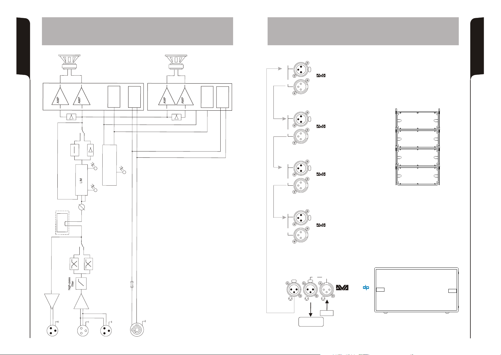
SCHEMA A BLOCCHI
BLOCK DIAGRAM
BLOCKSCHALTBILD
DIAGRAMA EM BLOQURES
”
8
1
O E
W OF R
®
RO
P
I
s D
a
l s
G
C
s D
l s
C a
DI
BU
i cht
w
S
s
PH SEA
e
s
a
0°
h se
h
P
10°8
P a
AI L
N
0 Bd
G
2
-
S
ye
de
l
p
Mo
up
g
S
PSSM
h
it
ow r
P
Swcin
S
TN
I
CU
R
I
C
L
coro
o
a t
e t n
er F
PFC
w
Corr c i
P
TRO
D
CO
EA Y
R
®
R
G
DIIPO
8
1
F R ”
WOO E
yo
oe
p
to
c
M dn
a
Da
l ss
C
D
S
s
Ca s l
hi g
SMP
itc
Sw
tiono
c
C
S pl
u
e
r
r r
r
e F
PF
ow
C r
Pwe
P
BALANCED
INPUT
BALANCED
LINK / OUT
BALANCED
INPUT
BALANCED
LINK / OUT
BALANCED
INPUT
BALANCED
LINK / OUT
1 = GND
2 = HOT
3 = COLD
PUSH
Digital Vertical Array
T
1 = GND
2 = HOT
3 = COLD
PUSH
Digital Vertical Array
T
1 = GND
2 = HOT
3 = COLD
PUSH
Digital Vertical Array
T
COLLEGAMENTI
CABLE CONNECTIONS
VERKABELUNG
CABLAGE
4
4
4
T
NS
P
E
N
S
l
a
on
t
p i
O
I U
y
l
ea
al
t
g
i i D
D
R
h
E-
B
c
V
U
w
O
S
s it
X
z9
0H
MITERI
L
BALANCED
INPUT
BALANCED
LINK / OUT
z 1 H
20
BALANCED
X-OVER
E
N
I
U
FS
MA S
OUTPUT
1
3
2
1 = GND
2 = HOT
3 = COLD
PUSH
4
Digital Vertical Array
T
BALANCED
MAIN INPUT
LINK
PUSHPUSH
SS
00
22
1 = GND
2
1
1
2
2 = HOT
3
3
3 = COLD
MIXER
DL E
TO
R
E
PU
NC
V
T
O
U
X-
A A
9
B
TI I U
D
CEL N
NP
A
A
A N
B
M
KI
LN
N
L
UM
P
I
S N T
IN
A
FULL RANGE
OUTPUT
10
Page 7
INSTALLAZIONE
INSTALLATION
INSTALLATIONEN
INSTALLATIONS
11
Utilizzo in appoggio
Supported use
Anwendung mit Aufstützung
Utilisation en appui
Impilato
Stacked
Aufgesetzt
Empilée
Utilizzo in appoggio verticale (DVA T4 montaggio “Ground stacking”)
Anwendung mit Aufst DVA T4 ““Ground stacking”
Supported use (DVA T4 ““Ground stacking” assembling)
Utilisation en appui (
ützung ( Zusammenbauen)
DVA T4 ““Ground stacking” installation)
12
Page 8

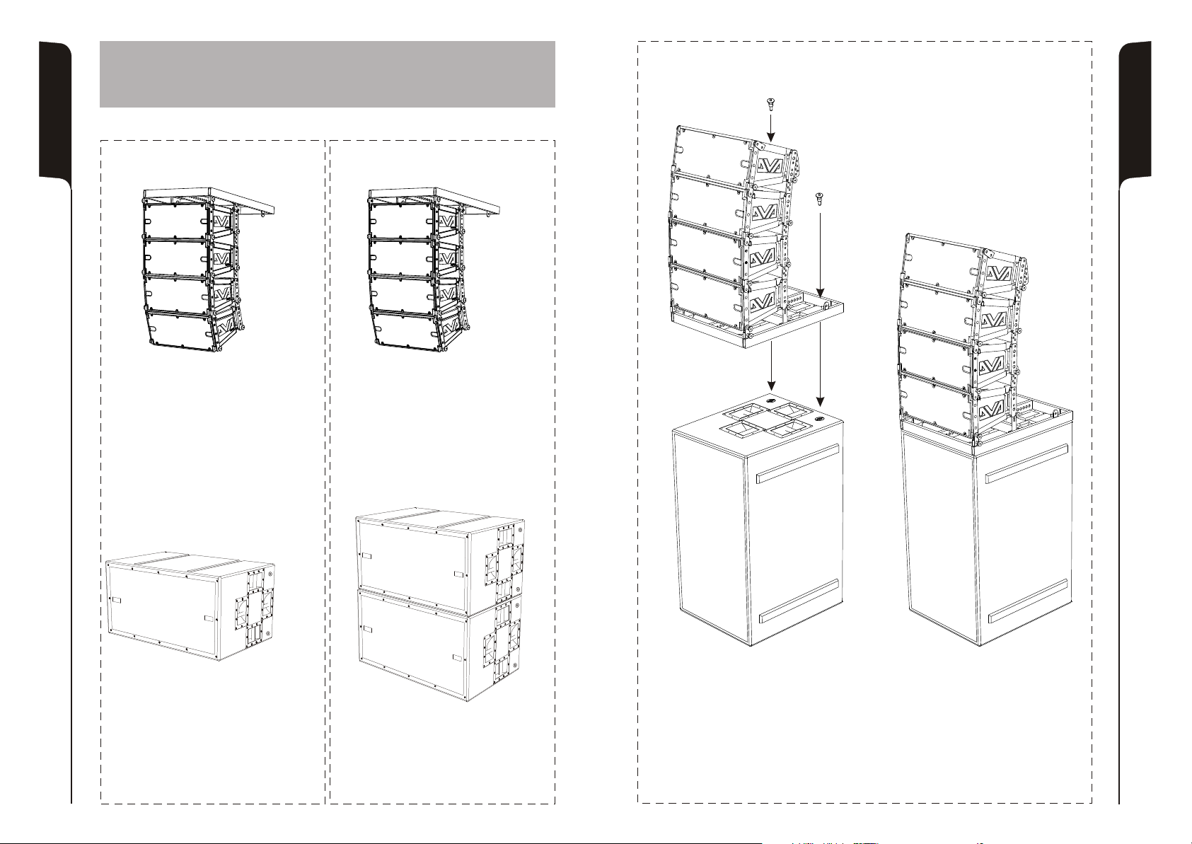
Opzione DSA 4
DSA 4 Option
In appoggio
Floor stack
Per supporto asta
Stand adaptor
In appoggio
Floor stack
Per supporto asta
Stand adaptor
Set di 4 ruote - opzione DWK 20
Set of 4 wheels - DWK 20 option
13
14
Page 9
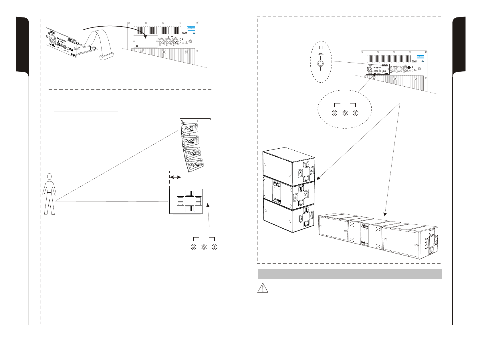
Digital Delay subwoofer - opzione SDD
Subwoofer Digital Delay - SDD option
ALLINEAMENTO SEGNALE AUDIO
ALIGNAMENT AUDIO SIGNAL
SS
SUBWOOFER DIGITAL DELAYSUBWOOFER DIGITAL DELAY
OPTIONAL CARDOPTIONAL CARD
dd
TECHNOLOGIESTECHNOLOGIES
dd
BB
SS
00
BALANCED
BALANCED
LINKLINK
X-OVER
X-OVER
OUTPUT
DD
DD
TECHNOLOGIESTECHNOLOGIES
BB
OUTPUT
1 = GND
1 = GND
11
11
22
22
2 = HOT
2 = HOT
33
33
3 = COLD
3 = COLD
22
BALANCED
BALANCED
MAIN INPUT
MAIN INPUT
PUSHPUSH
SUB-WOOFER
SUB-WOOFER
0°0°
120Hz120Hz
LEVEL
LEVEL
90Hz90Hz
180°180°
+10+10
LIMLIM
ONON SGNSGN
SUB
SUB
SUB
SUB
+4+4
PHASE
PHASE
XOVER
XOVER
0dB0dB
88
1122
33
CONFIGURAZIONE CARDIOIDE
CARDIOID CONFIGURATION
0°
180°
TECHNOLOGIESTECHNOLOGIES
dd
Ruotare la fase di 180°
Rotate 180° phase
SUB
PHASE
BALANCED
BALANCED
X-OVER
X-OVER
OUTPUT
PUSH
OUTPUT
11
22
33
BB
SS
00
22
BALANCED
BALANCED
LINKLINK
MAIN INPUT
MAIN INPUT
PUSHPUSH
SUB-WOOFER
SUB-WOOFER
0°0°
120Hz120Hz
LEVEL
LEVEL
90Hz90Hz
180°180°
+10+10
LIMLIM
ONON SGNSGN
SUB
SUB
SUB
SUB
+4+4
PHASE
PHASE
XOVER
XOVER
0dB0dB
1 = GND
1 = GND
11
22
2 = HOT
2 = HOT
33
3 = COLD
3 = COLD
88
1122
33
DELAY SET-UP
mSec
2
Impostare il delay a 4,5msec
20
30
10
0
90
80
70
- - -
.2
.3
3
1
.1
4
40
50
0
60
.4
.5
.0
5
6
.6
.9
9
8
.8
7
.7
.
Set delay to 4,5msec
GAP
15
Delay setup = (GAP X 1000) / 344
Delay = ms (espresso in millisecondi)
GAP = m (espresso in metri)
Velocità suono = 344 m/s
Delay = ms (specify milliseconds)
GAP = m (specify meters)
Sound speed = 344 m/s
DELAY SET-UP
mSec
2
20
30
10
0
90
80
70
- - -
.2
.3
3
1
.1
4
40
.0
50
5
0
6
60
.9
9
8
.8
7
.7
.
.4
.5
.6
ISTRUZIONI DI SICUREZZA PER ACCESSORI /
ZUBEHÖR NSTRUCTIONS DE SÉCURITÉ
SICHERHEITSHINWEISE / I POUR LES ACCESSOIRES
Contattare dB Technologies per gli accessori da utilizzare a corredo.
Si declina ogni responsabilità da un utilizzo inappropriato degli accessori o di dispositivi aggiuntivi non idonei allo
scopo.
Contact dB Technologies for accessories to be used with speakers.
Will not accept any responsibilty when inappropriate accessories or not suitable additional devices are used.
Kontaktieren sie dBTechnologies für passendes Lautsprecherzubehör.
Falls unpassendes Zubehör verwendet wird, wird jegliche Haftung ausgeschlossen.
Contact dBTechnologies pour les accessoires à utiliser avec la machine.
N'accepterons pas toutes les responsabilités lorsque des accessoires inappropriés ou ne conviennent pas à des
dispositifs supplémentaires sont utilisés.
SAFETY INSTRUCTIONS FOR ACCESSORIES
16
Page 10

Italiano
English
Deutsch
DVA Composer - Simulazione acustica di sistemi serie DVA
DVA Composer è un software di puntamento e simulazione acustica per tutti i modelli
Line Array della serie DVA e relativi Subwoofers.
Tale software permette di gestire un sistema stereo composto da line array e subs,
simulando separatamente la risposta acustica di entrambi.
Vengono inoltre fornite all'utente una serie di informazioni quali allineamento in fase
tra i sistemi sospesi e i relativi subwoofer a terra e vengono suggeriti angoli ottimali tra
i moduli line array e relativi preset di equalizzazione, al fine di ottimizzare le
performance del sistema anche per utenti non esperti.
Si raccomanda di scaricare gratuitamente il software DVA_Composer
DOWNLOAD
DVA Composer Acoustical Simulation and aiming for DVA Systems
DVA Composer is a 2D software for aiming and simulating acoustical response of all line
arrays and Subwoofers from DVA Series.
The software allows you to set up a stereo system composed by tops and subs, and
simulates separately the acoustical response of both.
DVA Composer also gives to the user all the information about phase alignment between
flown systems and ground stacked subwoofers, as well as it suggests an optimized
aiming of the line arrays modules and their suggested EQ presets, in order to guarantee
maximum performances even for non-expert customers.
DOWNLOAD
DVA Composer Akustiksimulation für Systeme der Serie DVA
DVA Composer ist eine Software zur Beschallungsplanung und simulation für alle Line
Array-Modelle der Serie DVA und den zugehörigen Subwoofern.
Sie ermöglicht die Verwaltung eines Stereosystems, das aus Line Arrays und Subwoofern
besteht, wobei das akustische Ansprechprofil jeweils separat simuliert wird.
Dem Nutzer werden eine Reihe von Daten geliefert, z.B. die Phasenanpassung zwischen
den Hängesystemen und den entsprechenden Subwoofern am Boden. Außerdem
werden die optimalen Winkel zwischen den Line Array-Modulen und den entsprechenden
Equalizer-Presets angegeben, so dass auch weniger erfahrene Benutzer die Leistungen
des Systems optimieren können.
DOWNLOAD
direttamente dal sito dB Technologies (www.dbtechnologies.com) nella
sezione dedicata «Software & Controller»
It is recommended to download DVA_Composer free software directly from
dB Technologies (www.dbtechnologies.com) in the special section «
Software & Controller»
Wir empfehlen, die Software DVA_Composer direkt von der Webseite dB
Technologies (www.dbtechnologies.com) im Abschnitt «software &
Controller» herunterzuladen
17
Français
DVA Composer Simulation acoustique de systèmes de séries DVA
DVA Composer est un logiciel de direction et simulation acoustique pour tous les
modèles de lignes de source de la série DVA et les caissons de basse relatifs.
Ce logiciel permet de gérer un système stéréo composé de ligne source et de
caissons de basse, simulant séparément la réponse acoustique de chacun des deux.
De plus, de nombreuses informations sont fournies à l'utilisateur, comme l'alignement
en phase entre les systèmes suspendus et les relatifs caissons de basse à terre, ou la
syggestion d'angles optimisés entre les modules de ligne de source et les préréglages
d'égaliseur relatifs. Cela permet d'optimiser les performances du système, même pour
des utilisateurs non experts.
On conseille de télécharger gratuitement le logiciel DVA_Composer
DOWNLOAD
directement à partir du site dB Technologies (www.dbtechnologies.com)
dans la section dédiée « Software & Controller »
18
 Loading...