

Page 1
SS
00
STEREO ACTIVE SUBWOOFER
A.E.B. INDUSTRIALE s.r.l.
Via Brodolini, 8 - 40056 Crespellano (Bo) - ITALIA
Tel. + 39 051 969870 - Fax. + 39 051 969725
Internet: www.dbtechnologies.com
E-mail: info@dbtechnologies-aeb.com
MANUALE D’USO
USER MANUAL
BEDIENUNGSANLEITUNG
CARACTERISTIQUES TECHNIQUES
Made in Italy
RR
digital power
COD. 420120162A Rev 4.0
Page 2

DESCRIZIONE
ItalianoItalianoItaliano
Manuale d’usoManuale d’uso
Il diffusore DVA S09dp è un subwoofer attivo della serie DVA (Digital Vertical Array)
equipaggiato con amplificatore DIGIPRO 1000s.
Questo è un amplificatore in classe D, ad alta efficienza, che permete di ottenere elevate
potenze di uscita con pesi ed ingombri ridotti. Grazie alla bassa potenza dissipata il
raffreddamento del modulo amplificatore avviene in modo statico, evitando l’uso di ventola.
Il circuito di alimentazione dell’amplificatore DIGIPRO , montato sul diffusore DVA S09dp,
è stato progettato per funzionare in modalità full-range; grazie alla tecnologia SMPS
(Switched-Mode Power Supplies) con PFC (Power Factor Correction) viene garantito il
funzionamento a tensioni di alimentazioni da 100Vac a 240Vac, assicurando stesse
prestazioni acustiche anche con linee di alimentazione fluttuanti e non stabilizzate.
Il diffusore DVA S09 dp è stato progettato per funzionare in modalità stereo o modalità
mono. E’ possibile settare la frequenza di incrocio (90Hz oppure 120Hz) e la rotazione di
fase (0° oppure 180°). I segnali di uscita possono essere link oppure pilotati dal circuito
XOVER.
Il DVA S09dp è realizzato in legno di betulla, studiato per sonorizzare ambienti di medie
dimensioni; è costruito utilizzando la tipologia “BAND PASS” che permette di ottenere alte
pressioni acustiche in dimensioni ridotte.
Per facilitare l’utilizzo, l’installazione e il trasporto è provvisto di:
- maniglie laterali (escluso DVA S09dp Bianco),
- supporto con filetto M20 per asta(escluso DVA S09dp Bianco),
- sedi per appoggio di un altro subwoofer, nella parte superiore del box,
- predisposizione per staffe appendibilità,
- predisposizione per ruote (escluso DVA S09dp Bianco).
®
®
COLLEGAMENTI
Collegamento alla alimentazione di rete
Ogni diffusore attivo è provvisto del proprio cavo di alimentazione. Il collegamento
avviene tramite un connettore modello Neutrik POWER CON® (blu) che permette di
avere una facile e rapita connessione al diffusore oltre che a un ottimo sistema di
bloccaggio.
Lo stesso connettore svolge la funzione di interruttore di rete.
L’apparecchio dovrà essere collegato ad una rete di alimentazione che possa erogare la
massima potenza richiesta.
Rilancio alimentazione di rete
Sul retro del diffusore è presente un connettore Neutrik POWER CON® (grigio) per il
rilancio dell’ alimentazione di rete.
Questa presa ha lo scopo di rilanciare l’alimentazione ad un altro diffusore riducendo i
collegamenti diretti alla rete. Gli assorbimenti massimi degli amplificatori sono riportati sul
pannello dell’amplificatore.
Il numero massimo dei diffusori collegati insieme varia sia per gli assorbimenti massimi
dei diffusori e sia dalla corrente massima della prima presa di alimentazione.
1
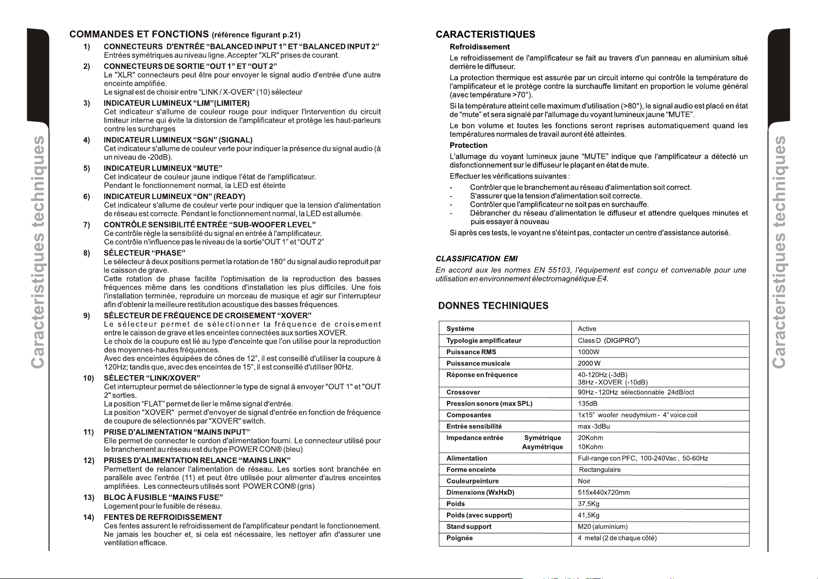
COMANDI E FUNZIONI (riferimento figura a pag.21)
1) CONNETTORI INGRESSO " BALANCED INPUTS” “INPUT 1” e " INPUT 2”
Connettori “XLR” di ingresso bilanciato a livello linea .
2) CONNETTORI DI USCITA “BALANCED OUTPUTS” "OUT 1”e "OUT 2”
I connettori “XLR” sono utilizzati per inviare il segnale audio ad un altro diffusore
amplificato.
Il tipo di segnale è selezionabile tramite l’interruttore” LINK/XOVER” (10)
3) INDICATORE LUMINOSO “LIM” (LIMITER)
Questo indicatore s’illumina di colore rosso per indicare l'intervento del circuito
limitatore interno, il quale evita la distorsione dell'amplificatore e protegge gli
altoparlanti da sovraccarichi.
4) INDICATORE LUMINOSO “SGN” (SIGNAL)
Questo indicatore s'illumina di colore verde per indicare la presenza del segnale
audio (ad un livello di -20dB).
5) INDICATORE LUMINOSO “MUTE”
Questo indicatore di colore giallo indica lo stato dell’amplificatore.
Nel normale funzionamento il led è spento.
6) INDICATORE LUMINOSO “ON” (READY)
Questo indicatore s'illumina di colore verde per indicare che la tensione di
alimentazione di rete è corretta.
Nel normale funzionamento il led è acceso.
7) CONTROLLO SENSIBILITA’ INGRESSO “SUB-WOOFER LEVEL”
Questo controllo regola la sensibilità del segnale in ingresso all’amplificatore.
Tale controllo non influisce sul livello dell’uscita “OUT 1” e “OUT 2”
8) SELETTORE “PHASE”
Questo interruttore a due posizioni permette la rotazione di 180°del segnale audio
riprodotto dal subwoofer.
La rotazione facilita l’ottimizzazione della riproduzione alle basse frequenze anche
nelle situazioni di installazioni difficili. Completata l’installazione, riprodurre un brano
musicale ed agire sull’interruttore per ottenere la migliore resa acustica alle basse
frequenze.
9) SELETTORE “XOVER”
Questo interruttore permette di selezionare la frequenza di incrocio tra subwoofer e i
diffusori collegati alle uscite “OUT 1” e “OUT 2”. La scelta del taglio è legata al tipo di
diffusore che si utilizza per la riproduzione delle frequenze medio-alte.
Per i diffusori con i coni a 12” è consigliabile utilizzare un taglio a 120Hz, mentre con i
diffusori con coni da 15” usare un taglio a 90Hz.
10) SELETTORE “LINK/XOVER”
Questo interruttore permette di selezionare il segnale da rilanciare sulle uscite “OUT
1” e “OUT 2”.
La posizione “LINK” permette di rilanciare lo stesso segnale di ingresso .
La posizione “XOXER” permette d’ inviare il segnale di ingresso tagliato alla
frequenza di incrocio selezionata tramite il selettore “XOVER” (9)
11) PRESA DI ALIMENTAZIONE “MAINS INPUT”
Consente la connessione del cavo di alimentazione e svolge la funzione di
interruttore di rete .
Il connettore utilizzato per il collegamento alla rete è un POWER CON® (blu)
12) PRESE DI ALIMENTAZIONE RILANCIO “MAINS LINK”
Consentono di rilanciare l’alimentazione di rete. Le ’uscite sono connesse in parallelo
con l’ingresso (11) e possono essere utilizzate per alimentare altri diffusori amplificati.
I connettori utilizzati sono POWER CON® (grigio).
13) PORTA FUSIBILE “MAINS FUSE”
Alloggio per fusibile di rete.
14) GRIGLIE DI RAFFREDDAMENTO
Queste griglie permettono il raffreddamento dell’amplificatore durante il
funzionamento. Non ostruire gli accessi e pulire le griglie quando necessita per
garantire il corretto circolo dell’aria.
ItalianoItalianoItaliano
Manuale d’usoManuale d’uso
2
Page 3
CARATTERISTICHE
Raffreddamento
Il raffreddamento dell’amplificatore avviene attraverso il pannello in alluminio posto sul
retro del diffusore.
La protezione termica è garantita da un circuito interno che controlla la temperatura
dell’amplificatore stesso e lo protegge dal surriscaldamento limitando in proporzione il
ItalianoItalianoItaliano
volume generale (con temperatura >70°).
Se la temperatura raggiunge quella massima di utilizzo (>80°), il segnale audio viene
posto in stato di “mute” e verrà segnalato tramite l’accensione dell’indicatore luminoso
giallo “MUTE”.
Il corretto volume e tutte le funzioni verranno riprese automaticamente al raggiungimento
delle normali temperature di esercizio.
Protezioni
L’accesione dell’indicatore luminoso giallo “MUTE” indica che l’amplificatore ha rilevato un
malfunzionamento sul diffusore, ponendolo in stato di mute.
Eseguire le seguenti verifiche:
- Controllare la corretta connessione alla rete d’alimentazione.
- Assicurarsi della corretta tensione d’alimentazione.
- Controllare che l’amplificatore non sia surriscaldato.
- Scollegare dalla rete di alimentazione il diffusore, attendere qualche minuto e
riprovare
Se dopo tale prove l’indicatore non si spenge contattare un centro assistenza autorizzato.
Manuale d’usoManuale d’uso
CLASSIFICAZIONE EMI
In accordo alle normative EN 55103, l'apparato è progettato e idoneo all'utilizzo in ambiente
Elettromagnetico E4.
DESCRIPTION
The DVA S09dp is an active subwoofer of DVA (Digital Vertical Array) series equipped with
DIGIPRO 1000s amplifier.
This class D high-efficiency amplifier, deliver high output power in a compact size and low
weight. Thanks to its high efficiency, the cooling of the amplifier module is obtained
statically, thus avoiding the use of a fan.
The power supply circuits of the DIGIPRO amplifier, assembled on DVA S09dp, has been
designed to work in full-range mode; thanks to the SMPS (Switched-Mode Power
Supplies) technology with PFC (Power Factor Correction) the operation with supply
voltages between 100 Vac and 240Vac is guaranteed by ensuring the same sound
performances even with floating and non-stabilized power supply systems.
The DVA S09dp speaker is designed to function in stereo and in mono modes. It is possible
to set crossover frequency (90Hz or 120Hz) and turning of phase (0° or 180°).
The output signals can be linked or controller by X-OVER circuit.
DVA S09dp is made of birch wood, designed for medium size rooms. The subwoofer
speaker is made using “BAND PASS” so that high sound pressures can be achieved in
compact dimensions.
For easy use, installation and transport, are provided with:
- handles on sides (DVA S09dp White excluded),
- standard (M20) pole mount plate (DVA S09dp White excluded),
- top part of the box features recesses for making it easier to superimpose another
- rigging predisposition
- wheels predisposition (DVA S09dp White excluded)
®
®
subwoofer.
EnglishEnglishEnglish
user manualuser manual
CONNECTIONS
DATI TECNICI
Sistema Attivo
Tipologia amplificatore Classe D (DIGIPRO )
Potenza RMS 1000W
Potenza musicale 2000W
Risposta in frequenza 40-120Hz (-3dB)
Crossover 90Hz - 120Hz selezionabile , 24dB/oct
Pressione sonora (max SPL) 135dB
Componenti 1x15” woofer neodimio, 4” voice coil
Sensibilità ingresso max -3dBu
Impedenza ingresso Bilanciato 20Kohm
Alimentazione Full-rangeconPFC, 100-240Vac, 50-60Hz
Forma diffusore Rettangolare
Colore diffusore Nero
Dimensioni (WxHxD) 515x440x720mm
Peso 37,5Kg
Peso (con staffe per appendibità) 41,5Kg
Supporto piantana M20 (alluminio)
3
Maniglie 4 in metallo (2 per lato)
Sbilanciato 10Kohm
38Hz - XOVER (-10dB)
®
Connecting to the mains supply
Each active speaker features its own power cable. Connection is done by a Neutrik
POWER CON® (blue) model which permits easy and fast connection to the speaker as
well as being an excellent locking system.
The same connector serves as a switch to turn ON and OFF the active loudspeaker by
turning the connector to the left (OFF) or right (ON).
The active speaker must be connected to a power supply able to deliver the maximum
required power.
Main power supply linking
On the rear of the speaker, a Neutrik POWER CON® connector (grey) offers linking the
mains power supply.
This socket links the power supply to another speaker, thereby reducing the direct
connections to the mains. Maximum amplifier input power is shown on the amplifier panel.
The maximum number of speakers connected together varies of max input power and of
the maximum allowed current of the first power socket.
4
Page 4

CONTROLS AND FUNCTIONS (picture ref. pag.21)
1) " BALANCED INPUT 1” AND " BALANCED INPUT 2”INPUT CONNECTORS
Balanced inputs at line level. Accept “XLR” sockets.
2) "OUT 1 ” AND "OUT 2 ” OUTPUT CONNECTORS
The “XLR” connectors be used to send the input audio signal to another amplified
EnglishEnglishEnglish
user manualuser manual
speaker.
The signal is choosing between “LINK/XOVER” (10) switch.
3) “LIM” LIMITER INDICATOR LIGHT
This indicator shows red to indicate that the internal limiter starts working.
This prevents amplifier distortion and protects the speakers against overloads.
4) “SGN” SIGNAL INDICATOR LIGHT
This indicator shows green to indicate the presence of the audio signal (at a level of 20dB).
5) “MUTE” INDICATOR LIGHT
This yellow indicator indicates amplifier status.
The LED is off in normal operating conditions.
6) “ON” READY INDICATOR LIGHT
This indicator shows green to indicate that the main power voltage is correct.
The LED shows green normal operating conditions
7) “SUBWOOFER LEVEL” INPUT SENSITIVITY CONTROL
This control adjusts the sensitivity of the signal amplifier input.
This control does not affect the "OUT 1 ” and "OUT 2 ” outputs levels
8) “PHASE” SWITCH
This two-position switch permits turning the audio signal’s phase by 180°.
Rotation makes it easier to optimise the reproduction of the low frequencies even in
the most difficult installation situations. After completing installation, play a piece of
music and move the switch to achieve the best sound reproduction at low
frequencies.
9) “XOVER” SWITCH
This switch permits selecting the crossover frequency between the
subwoofer and the speakers connected to the "OUT 1 ” and "OUT 2 ” outputs.
Choice depends on the type of speaker used for reproduction of mid-high
frequencies.
For speakers with 12” cones, it is best to use 120Hz, while with 15”
speakers 90Hz.
10) "LINK/XOVER" SWITCH
This switch allows to select the signal type to send "OUT 1 ” and "OUT 2 ” outputs.
The “LINK” position allows to link the same input signal.
The “XOVER” position allows to send input signal according to crossover frequency
select by XOVER (9) switch.
11) "MAINS INPUT" POWER SOCKET
For connecting the power cable provided.
The connector used for mains connection is a POWER CON® (blue) socket.
12) “MAINS LINK” POWER SOCKETS
For linking the mains power. The outputs are connected in parallel with input (11) and
can be used to power other active speakers.
The connectors are POWER CON® (grey) sockets.
13) "MAINS FUSE" FUSE CARRIER
Mains fuse housing.
14) COOLING GRILLE
These grilles permit cooling the amplifier during operation.
Do not block accesses and clean the grilles whenever necessary to ensure correct
air circulation.
5
CHARACTERISTICS
Cooling
The amplifier is cooled by means of the aluminium panel placed on the back of the speaker.
The thermal protection is ensured by an internal circuit which controls the temperature of
the amplifier and protects this against any risk of overheating thus limiting in proportion the
general volume ( temperature >70°C).
If the temperature reaches the maximum operating temperature (>80°C), the audio signal
is set to the “MUTE” position and it will be indicated by the switching on of the yellow
“MUTE” LED.
The requiriered volume and all functions will be restored automatically when the normal
operating temperatures are reached.
Protections
When the yellow “MUTE” LED turns on, it means that a malfunction has been detected on
the speaker, thus setting this to the mute position.
Perform the checks listed below:
- Check if the speaker is properly connected to the power supply.
- Make sure that the power supply is of correct voltage.
- Check that the amplifier is not overheated.
- Disconnect the speaker from the mains power supply, wait for a few minutes and
connect it again.
If after these tests the yellow “MUTE” LED is still on, please contact an authorised service
centre.
EMI CLASSIFICATION
According to the standards EN 55103 this equipment is designed and suitable to operate in E4
Electromagnetic environment.
TECHNICAL SPECIFICATIONS
System Active
Type of amplifier Class D (DIGIPRO )
RMS power 1000W
Music power 2000W
Frequency response 40-120Hz (-3dB)
Crossover 90Hz - 120Hz selectable 24dB/oct
Sound pressure (max SPL) 135dB
Woofer 1x15” neodymium - 4” voice coil
Input sensitivity max -3dBu
Impedance input Balanced 20Kohm
Unbalanced 10Kohm
Power supply Full-range with PFC, 100-240Vac, 50-60Hz
Housing shape Rectangular
Colour Black
Dimension (WxHxD) 515x440x720mm
Weight 37,5Kg
Weight (with brackets) 41,5 Kg
Pole mount cup M20 (aluminium)
Handle 4 metal (2 per side)
38Hz - XOVER (-10dB)
®
EnglishEnglishEnglish
user manualuser manual
6
Page 5

BESCHREIBUNG
®
DeutschDeutschDeutsch
Der DVA S09dp ist ein aktver Subwoofer der DVA Serie und ist mit einem digipro 1000s
Verstärker ausgestattet. Dieser Class-D -Verstärker Hochleistungsverstärker ermöglicht
eine hohe Ausgangsleistungen bei geringstem Gewicht und kompakten Abmessungen.
Dank der sehr geringen Verlustleistung erfolgt die Kühlung des Verstärkermoduls durch
Konvektion, ohne Einsatz eines Lüfters.
Die Versorgungsspannung des DVA S09dp wurde für den Vollbereichs-Betrieb ausgelegt.
Dank der SMPS- Technologie (Switched-Mode Power Supplies) mit PFC (Power Factor
Correction) wird der Arbeitsbereich bei Versorgungsspannungen zwischen 100V AC und
240V AC gewährleistet, wobei die gleichen Ausgangsleistungen auch bei schwankenden
und nicht stabilisierten Versorgungsleitungen garantiert sind.
Die aktiven Subwoofer sind sowohl für den Stereobetrieb und Monobetrieb konzipiert. Die
Trennfrequenz kann entwerde zu 90 Hz oder 120 Hz gewählt werden, ebenso die Phase
entweder zu 0° oder 180°. Das Ausgangssignal der XLR- Buchse kann als LINK oder XOVER gewählt werden.
DVA S09dp ist ein aktiver Subwoofer mit Holzgehäusen, der für die Beschallung von
mittelgroßen bis großen Räumen hergestellt wurden.
Als Bandpass-Subwoofer bietet der DVA S09dp trotz seiner kompakten Abmessungen
einen beachtlich hohen Schalldruck.
Zur einfachen Anwendung, Installation und Transport, ist der Subwoofer ausgestattet mit:
- Seitlichen Griffen (DVA S09dp White ausgeschlossen)
- M20 Hochständerflansch (DVA S09dp White ausgeschlossen)
- Einfräsungen auf der Oberseite um das Aufstellen eines weiteren Subwoofers zu
erleichtern.
- Flughardware SRK 09 (optional)
ANSCHLÜSSE
BedienungsanleitungBedienungsanleitung
Netzanschluss
Jeder Aktivlautsprecher hat ein eigenes Netzkabel. Der Anschluss erfolgt mit einem
Netzstecker Neutrik POWER CON® (blau), der den einfachen und schnellen Anschluss
des Lautsprechers erlaubt und eine sichere Verriegelung garantiert. Der Stecker dient
zugleich als Schalter zum Einschalten und Ausschalten der Lautsprecher.
Das Gerät muss an ein Netz angeschlossen werden, dass die verlangte maximale
Leistung abgeben kann.
Power-Weiterführung
Auf der Rückseite des Lautsprechers befinden sich zwei Einbaukupplungen Neutrik
POWER CON® (grau) für die Weiterleitung der Netzstromversorgung.
Über diese Steckbuchse kann man einen anderen Lautsprecher anschließen, um die
Anzahl der direkten Netzanschlüsse zu reduzieren. Die maximale Stromaufnahme der
Verstärker ist auf ihrem Typenschild angegeben.
Die Anzahl, der maximal aneinander anschließbaren Lautsprecher ist abhängig von
deren maximalen Stromaufnahme und von der maximalen Stromabgabe der ersten
Netzsteckdose.
7
BEDIENELEMENTE UND FUNKTIONEN (Hinweis siehe, S.21)
1) EINGANGSBUCHSE "BALANCED INPUT1” UND "BALANCED INPUT 2”
Symmetrischer XLR Eingang für Line-Pegel.
2) AUSGANGSBUCHSE "OUT 1” UND "OUT 2”
Zur Weiterleitung des Signals an weitere Lautsprecher. Das Signal kann als LINK/XOVER gewählt werden. Siehe (10).
3) LED “LIM” (LIMITER)
Diese rote LED leuchtet auf, um das Ansprechen der Limiterschaltung zu
signalisieren, welche die Verzerrung des Verstärkers verhindert und die Lautsprecher
gegen Überlastung schützt.
4) LED “SGN” (SIGNAL)
Diese LED leuchtet grün, wenn das Audiosignal anliegt (mit einem Pegel von -20dB).
5) LED “MUTE”
Diese gelbe LED zeigt den Zustand “MUTE” des Verstärkers an.
Während des normalen Betriebs ist die LED ausgeschaltet.
6) LED “ON” (READY)
Diese LED leuchtet grün, wenn das Gerät an die richtige Netzspannung
angeschlossen ist. Während des normalen Betriebs leuchtet die LED.
7) EMPFINDLICHKEITS REGLER EINGANG “SUBWOOFER LEVEL”
Dieser Regler dient zum Einstellen der Eingangs-Empfindlichkeit des Verstärkers für
den Subwoofer. Diese Einstellung beeinflusst nicht den Ausgangspegel der Buchsen
"OUT 1” UND "OUT 2”.
8) WAHLSCHALTER “PHASE”
Der Schalter dreht die Phase um 180°.
Durch das Drehen der Phase kann man die Wiedergabe der Bässe auch bei
ungünstigen akustischen Bedingungen in einfacher Weise optimieren. Nach
Abschluss der Installation ein Musikstück abspielen und ausprobieren, in welcher
Schaltstellung die tiefen Frequenzen am besten klingen.
9) WAHLSCHALTER FÜR DIE CROSSOVER-FREQUENZ “X-OVER”
Der Wahlschalter mit zwei Schaltstellungen dient zur Wahl der Crossover-Frequenz
zwischen dem Subwoofer und den Lautsprechern am Ausgangs X-OVER.
Die Wahl der Trennfrequenz sollte vom Lautsprechertyp abhängig gemacht werden,
der für die Wiedergabe der mittleren und hohen Frequenz verwendet wird.
Bei 12” Lautsprechern empfiehlt sich die Trennfrequenz 120 Hz und bei 15”Lautsprechern die Trennfrequenz 90 Hz.
10) WAHLSCHALTER “LINK/XOVER”
Er konfiguriert, welches Signal an den Buchsen OUT 1 und 2 ausgegeben werden
soll: In der Stellung “LINK” wird das Eingangs-Signal der Buchsen (1) parallel
abgegriffen . Nun können z.B. Weitere Subwoofer angeschlossen werden.
In der Stellung “X-OVER” wird der Hochpass der aktiven Frequenzweiche “XOVER” ausgegeben zum Anschluss der Satellitenlautsprecher.
11) EINBAUKUPPLUNG “MAINS INPUT”
Für den Anschluss des Netzkabels.
Für den Netzanschluss wird ein POWER CON® (blau) Einbaukupplung verwendet.
12) EINBAUKUPPLUNG FÜR DIE POWER-WEITERLEITUNG “MAINS LINK”
Er dient zum Durchschleifen der Netzspannung. Der Ausgang ist parallel an den
Eingang (11) angeschlossen und kann zur Versorgung eines weiteren aktiven
Lautsprechers verwendet werden.
Der Steckverbinder ist eine POWER CON® (grau) Einbaukupplung .
13) SICHERUNGSHALTER “MAINS FUSE”
Er enthält die Netzsicherung.
14) LÜFTUNGSGITTER
Diese Gitter erlauben die Kühlung der Endstufe während des Betriebs. Die
Lüftungsöffnungen nicht abdecken und die Gitter nötigenfalls säubern, um die
ordnungsgemäße Luftzirkulation zu gewährleisten.
DeutschDeutschDeutsch
BedienungsanleitungBedienungsanleitung
8
Page 6
MERKMALE
Kühlung
Die Kühlung des Verstärkers erfolgt durch die Aluminiumplatte an der Rückseite des
Lautsprechers.
Der Hitzeschutz ist durch einen internen Schaltkreis gewährleistet, der die Temperatur des
Verstärkers überwacht und diesen vor Überhitzung schützt, indem die generelle
Lautstärke begrenzt wird ( bei Temperaturen >70°).
DeutschDeutschDeutsch
BedienungsanleitungBedienungsanleitung
9
Wenn die Temperatur den maximalen Betriebswert erreicht (>80°), wird das Audiosignal
auf „mute“ gesetzt, was durch das Aufleuchten der gelben Kontrolllampe „MUTE“
angezeigt wird.
Die volle Lautstärke und sämtliche Funktionen werden automatisch wieder
aufgenommen, sobald die normale Betriebstemperatur wieder erreicht wird.
Schutz
Das Aufleuchten der gelben Kontrolllampe “MUTE” bedeutet, dass der Verstärker eine
Funktionsstörung des Lautsprechers festgestellt und diesen daher in den Mute- Zustand
versetzt hat.
In diesem Fall ist folgendes zu überprüfen:
- Den korrekten Anschluss an das Stromnetz kontrollieren
- Sicher stellen, dass die richtige Versorgungsspannung vorliegt
- Kontrollieren, dass der Verstärker nicht überhitzt ist.
- Den Lautsprecher vom Stromnetz trennen, einige Minuten abwarten und ihn dann
nochmals anschließen.
Wenn die Kontrolllampe auch nach dieser Wartezeit nicht erlischt, bitte eine qualifizierte
Kundendienststelle kontaktieren.
EMV Einstufung
Entsprechend der Norm EN 55103 ist diese Gerät entwickelt um in E4 elektromagnetischen
Umgebungen zu arbeiten.
TECHNISCHE DATEN
System Aktiv
Verstärker typ Class D (DIGIPRO )
RMS Leistung 1000W
Musikleistung 2000 W
Frequenzgang 40-120Hz (-3dB)
Crossover 90Hz - 120Hz Wählbare 24dB/oct
Schalldruck (max SPL) 135dB
Komponenten 1x15” Neodymwoofer - 4” voice coil
Empfindlich keit Eingang max -3dBu
Impedanz Eingang Symmetrisch 20Kohm
Unsymmetrisch 10Kohm
Netzspannung Vollbereich mit PFC, 100-240Vac, 50-60Hz
Gehäuseform Rechteckig
Farbe Schwarz
Abmessungen (BxHxT) 515x440x720mm
Gewicht 37,5 Kg
Gewicht (mit Flughardware) 42,5Kg
Ständerflansch M20 (aluminium)
Griffe 4 Metal (2 pro Seite)
38Hz - XOVER (-10dB)
®
DESCRIPTION
Le diffuseur DVA S09dp est un subwoofer actif série DVA (Digital Vertical Array) équipé
de l'amplificateur DIGIPRO 1000s. Cet est un amplificateur en classe D, de très haute
efficacité, permet d'obtenir des puissances de sorties élevées avec des poids et
encombrements réduits. Grâce à la basse puissance dissipée, le refroidissement du
module amplificateur se fait de manière statique évitant l'utilisation de ventilateur.
Le circuit d'alimentation de l'amplificateur DIGIPRO , monté sur DVA S09dp diffuseur, a
été conçu pour fonctionner en modalité full-range ; grâce à la technologie SMPS
(Switched-Mode Power Supplies) avec PFC (Power Factor Correction), le fonctionnement
à tensions d'alimentations de 100Vac à 240Vac, assurant les mêmes prestations
acoustiques même avec des lignes d'alimentation fluctuantes et non stabilisées.
Diffuseur DVA S09dp ont un sub-woofer actif conçu pour fonctionner en modalité stéréo ou
en modalité mono. Il est possible de configurer la fréquence de coupure (90Hz ou 120Hz)
et tournant de phase (0 ° ou 180 °). Les signaux de sortie pourrait être lié ou de contrôle par
XOVER le circuit.
DVA S09dp est un diffuseur actif en bois de bouleau, étudiés pour la sonorisation des lieux
moyennement grands, est réalisée en utilisant la typologie “ BAND PASS ”, qui permet
d'obtenir des pressions acoustiques élevées avec des dimensions réduites.
Pour faciliter l’utilization, l’installation et le transport le subwoofer est pourvus de:
- poignées latéraux DVAS09dp Blanc exclus ,
- support avec filet M20 pour hampe DVAS09dp Blanc exclus ,
- sièges pour appui de autre subwoofer dans la partie supérieure du box même,
- prédisposition pour support à suspendre,
- prédisposition roues DVAS09dp Blanc exclus
®
®
()
()
()
BRANCHEMENTS
Branchement au réseau d'alimentation
Chaque enceinte active est dotée de son cordon d'alimentation. Le branchement
s'effectue au moyen d'un connecteur modèle Neutrik POWER CON® (bleu) qui rend aisé
et rapide le branchement de l'enceinte et assure un excellent blocage.
Le même connecteur sert de passage à allumer et éteindre le haut-parleur.
L'appareil doit être branché à un réseau d'alimentation en mesure de fournir la puissance
maximum requise.
Relance alimentation de réseau
À l'arrière de l'enceinte, on trouve un connecteur Neutrik POWER CON® (gris) pour la
relance de l'alimentation de réseau.
Cette prise sert pour relancer l'alimentation à une autre enceinte et réduire ainsi les
branchements directs au réseau. Les absorptions maximums des amplificateurs sont
reportées sur la façade de l'amplificateur.
Le nombre maximum d'enceintes pouvant être reliées varie aussi bien en fonction des
absorptions maximums des enceintes que du courant maximum de la première prise
d'alimentation.
Français
Caracteristiques techniquesCaracteristiques techniques
10
Page 7
Français
Français
11
Caracteristiques techniquesCaracteristiques techniques
Caracteristiques techniquesCaracteristiques techniques
121314
Page 8

10
SCHEMA A BLOCCHI
BLOCK DIAGRAM
BLOCKSCHALTBILD
5
6
3
4
DIAGRAMA EM BLOQURES
BALANCED
OUTPUTS
BALANCED
INPUTS
1 = GND
2 = HOT
3 = COLD
OUT 1 OUT 2
1
2
3
INPUT 1
PUSHPUSH PUSHPUSH
12
3
MONO
INPUT 2
TECHNOLOGIESTECHNOLOGIES
d
LINK
XOVER
MUTE
LIM
SGN
ON
SUB-WOOFER
LEVEL
PHASE
XOVER
120Hz
90Hz
0dB
0°
Stereo
180°
0dB
8
Mono
B
0
S
STEREO ACTIVE SUBWOOFER
9
8
7
14
BALANCED
CH1 INPUT
BALANCED
CH1 OUT
BALANCED
CH2 INPUT
BALANCED
CH2 OUT
FULL RANGE
MAINS INPUT
MAINS LINK
LINK
XOVER
LINK
XOVER
L
N
MAINS LINK
L
N
XOVER FREQ
L
N
XOVER FREQ
XOVER
XOVER
MAINS
FUSE
LIMITER
uPROCESSOR
LIMITER
SIGNAL
DIGIPRO
E
S
UV
L M
HE
O
PA
Switching Mode
MUTE
READY
Power Factor
®
WOOFER 15”
Class D
Class D
SMPS
Power Supply
PFC
Correction
2
1
12
11
MAINS LINK
220-240V~ MAX 15A
100-120V~ MAX 10A
O
N
F
F
O
O
N
F
F
O
FULL RANGE MAINS INPUT
100-240V~ 50-60Hz
1250W MAX
ACTIVE P.F.C.
F
F
O
MAINS FUSE
220-240V~ (T5A 250V)
100-120V~ (T10A 250V)
O
N
digital powerdigital powerdigital powerdigital power
“CAUTION”
TO PREVENT ELECTRICAL SHOCK
DO NOT REMOVE COVER
“AVIS”
RISQUE DE CHOCH ELECTRIQUE
NE PAS OUVRIR
SERIAL N.SERIAL N.
Made in Italy
14
13
Page 9

CONFIGURAZIONI e
CONFIGURATION and
CABLE CONNECTIONS
KONFIGURATIONEN und
CONFIGURATIONS et
COLLEGAMENTI
VERKABELUNG
CABLAGE
CONFIGURAZIONI e
CONFIGURATION and
CABLE CONNECTIONS
KONFIGURATIONEN und
CONFIGURATIONS et
COLLEGAMENTI
VERKABELUNG
CABLAGE
BALANCED
OUTPUTS
BALANCED
INPUTS
1 = GND
2 = HOT
3 = COLD
BALANCED
INPUT
BALANCED
LINK / OUT
BALANCED
INPUT
BALANCED
LINK / OUT
BALANCED
INPUT
BALANCED
LINK / OUT
BALANCED
INPUT
BALANCED
LINK / OUT
OUT 1 OUT 2
11
22
33
INPUT 1
PUSHPUSH PUSHPUSH
12
3
MONO
MIXER
LINK
LINK
XOVER
XOVER
OUT 1 OUT 2
BALANCED
OUTPUTS
11
22
33
INPUT 1
LINK
XOVER
MUTE
LIM
SGN
ON
INPUT 2
SUB-WOOFER
LEVEL
PHASE
XOVER
0°
120Hz
90Hz
180°
0dB
8
Mono
SS
00
MIXER
1 = GND
2 = HOT
3 = COLD
PUSH
4
Digital Vertical Array
T
1 = GND
2 = HOT
3 = COLD
PUSH
4
Digital Vertical Array
T
1 = GND
2 = HOT
3 = COLD
PUSH
4
Digital Vertical Array
T
1 = GND
2 = HOT
3 = COLD
PUSH
4
Digital Vertical Array
T
BALANCED
INPUTS
BALANCED
OUTPUTS
BALANCED
INPUTS
BALANCED
INPUT
BALANCED
LINK / OUT
BALANCED
INPUT
BALANCED
LINK / OUT
BALANCED
INPUT
BALANCED
LINK / OUT
BALANCED
INPUT
1 = GND
2 = HOT
3 = COLD
1 = GND
2 = HOT
3 = COLD
PUSHPUSH PUSHPUSH
12
3
MONO
MIXER
OUT 1 OUT 2
11
22
33
INPUT 1
PUSHPUSH PUSHPUSH
12
3
MONO
LINK
XOVER
MUTE
LIM
SGN
ON
INPUT 2
INPUT 2
1 = GND
2 = HOT
3 = COLD
PUSH
1 = GND
2 = HOT
3 = COLD
PUSH
1 = GND
2 = HOT
3 = COLD
PUSH
1 = GND
2 = HOT
3 = COLD
PUSH
XOVER
XOVER
Digital Vertical Array
Digital Vertical Array
Digital Vertical Array
120Hz
90Hz
LINK
XOVER
120Hz
90Hz
PHASE
180°
PHASE
0°
180°
T
T
T
SUB-WOOFER
0°
MUTE
ON
SUB-WOOFER
4
4
4
LEVEL
0dB
8
Mono
LIM
SGN
LEVEL
0dB
8
Mono
LINK
XOVER
00
SS
0dB
Stereo
LINK
XOVER
00
SS
0dB
Stereo
MIXER
15
BALANCED
LINK / OUT
Digital Vertical Array
T
4
16
Page 10

CONFIGURAZIONI e
CONFIGURATION and
CABLE CONNECTIONS
KONFIGURATIONEN und
CONFIGURATIONS et
COLLEGAMENTI
VERKABELUNG
CABLAGE
CONFIGURAZIONI e
CONFIGURATION and
CABLE CONNECTIONS
KONFIGURATIONEN und
CONFIGURATIONS et
COLLEGAMENTI
VERKABELUNG
CABLAGE
BALANCED
OUTPUTS
BALANCED
INPUTS
11
22
33
1 = GND
12
2 = HOT
3
3 = COLD
MIXER
MONO
ACTIVE SPEAKER
BALANCED
INPUT
PUSH
LINK
OUT
FLAT
STAGE MONITOR
OUT 1 OUT 2
INPUT 1
INPUT 2
PUSHPUSH PUSHPUSH
MONO
XOVER
120Hz
90Hz
ACTIVE SUBWOOFER
STEREO
ACTIVE SPEAKER
BALANCED
INPUT
LIMITER
SIGNAL
MUTE
READY
+4dB
0dB
8
-3dB
SENSITIVITY
MODE
LINK
LINK
XOVER
XOVER
LINK
XOVER
MUTE
LIM
SGN
ON
SUB-WOOFER
LEVEL
PHASE
0dB
0°
Stereo
180°
0dB
8
Mono
PUSH
BALANCED
OUTPUTS
BALANCED
INPUTS
1 = GND
2 = HOT
3 = COLD
LINK
OUT
OUT 1 OUT 2
11
22
33
INPUT 1
PUSHPUSH PUSHPUSH
12
3
MONO
MIXER
STAGE MONITOR
FLAT
INPUT 2
MIXER
LIMITER
SIGNAL
MUTE
READY
8
SENSITIVITY
MODE
ACTIVE SPEAKER
PUSH
+4dB
0dB
-3dB
LINK
XOVER
MUTE
LIM
SGN
ON
SUB-WOOFER
LEVEL
PHASE
XOVER
0°
120Hz
90Hz
180°
0dB
8
Mono
ACTIVE SUBWOOFER
BALANCED
INPUT
0dB
Stereo
LINK
OUT
LINK
LINK
XOVER
XOVER
STAGE MONITOR
LIMITER
SIGNAL
MUTE
READY
+4dB
0dB
8
-3dB
SENSITIVITY
FLAT
MODE
BALANCED
OUTPUTS
BALANCED
INPUTS
BALANCED
OUTPUTS
BALANCED
INPUTS
1 = GND
2 = HOT
3 = COLD
1 = GND
2 = HOT
3 = COLD
OUT 1 OUT 2
11
22
33
INPUT 1
PUSHPUSH PUSHPUSH
12
3
MONO
OUT 1 OUT 2
11
22
33
INPUT 1
PUSHPUSH PUSHPUSH
12
3
MONO
MIXER
MONO
LINK
XOVER
ON
INPUT 2
ACTIVE SUBWOOFER
INPUT 2
SUB-WOOFER
PHASE
XOVER
0°
120Hz
90Hz
180°
LINK
XOVER
ON
SUB-WOOFER
PHASE
XOVER
0°
120Hz
90Hz
180°
ACTIVE SUBWOOFER
MONO
BALANCED
INPUT
PUSH
LINK
BALANCED
OUTPUTS
BALANCED
INPUTS
BALANCED
OUTPUTS
BALANCED
INPUTS
1 = GND
2 = HOT
3 = COLD
1 = GND
2 = HOT
3 = COLD
OUT
OUT 1 OUT 2
11
22
33
INPUT 1
PUSHPUSH PUSHPUSH
12
3
MONO
OUT 1 OUT 2
11
22
33
INPUT 1
PUSHPUSH PUSHPUSH
12
3
MONO
MUTE
LIM
SGN
LEVEL
0dB
Stereo
0dB
8
Mono
LINK
XOVER
MUTE
LIM
SGN
LEVEL
0dB
Stereo
0dB
8
Mono
STAGE MONITOR
INPUT 2
INPUT 2
LIMITER
SIGNAL
MUTE
READY
SENSITIVITY
FLAT
+4dB
0dB
8
-3dB
MODE
LINK
XOVER
ON
PHASE
XOVER
0°
120Hz
90Hz
180°
ACTIVE SPEAKER
MUTE
LIM
SGN
SUB-WOOFER
LEVEL
0dB
Stereo
0dB
8
Mono
LINK
XOVER
ACTIVE SUBWOOFER
LINK
XOVER
LINK
XOVER
MUTE
LIM
SGN
ON
SUB-WOOFER
LEVEL
PHASE
XOVER
0dB
0°
120Hz
Stereo
90Hz
180°
0dB
8
Mono
ACTIVE SUBWOOFER
MIXER
17
MIXER
MIXER
MIXER
MIXER
MIXER
18
Page 11
INSTALLAZIONE DEL DIFFUSORE
LOUDSPEAKER INSTALLATION
INSTALLATION DES LAUTSPRECHERS
INSTALLATION DU DIFFUSEUR
I
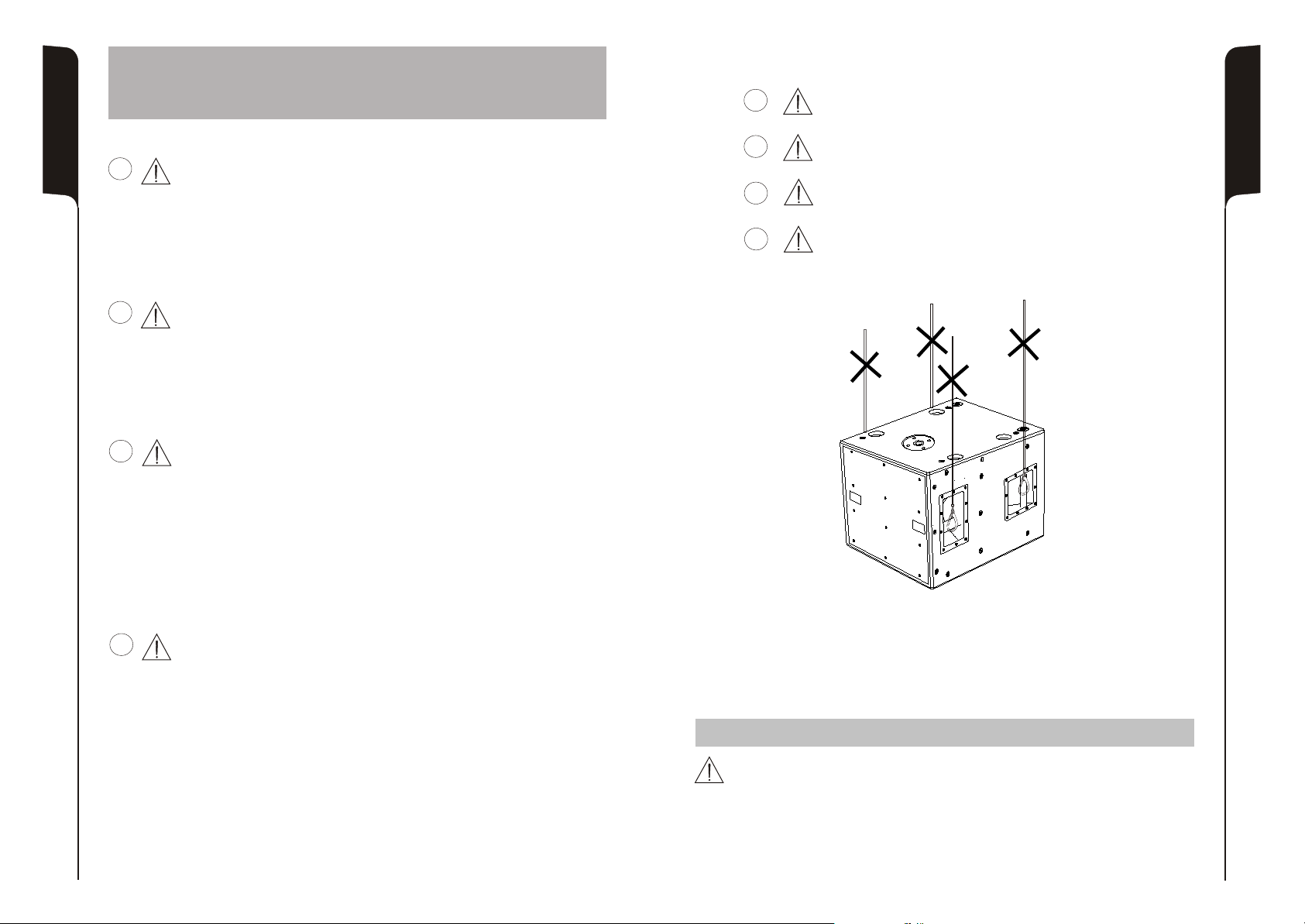
ATTENZIONE
Non utilizzare mai le maniglie per appendere il diffusore!
19
E
D
F
I
ATTENZIONE
Installare il diffusore in modo stabile e sicuro, così da evitare qualsiasi condizione
di pericolo per l’incolumità di persone e strutture.
Per evitare condizioni di pericolo non sovrapporre fra loro più diffusori senza
adeguati sistemi di ancoraggio.
Nell’utilizzo all’aperto evitare luoghi esposti alle intemperie.
Il diffusore viene fornito dalla ditta costruttrice predisposto per l’utilizzo in
appoggio.
D
F
E
WARNING
Never use the handles to hang the speaker!
VORSICHT
Hängen Sie den Lautsprecher nie an den Griffen auf!
ATTENTION
Ne jamais utiliser les poignées pour suspendre l'enceinte!
WARNING
Make sure that the loudspeaker is securely installed in a stable position to avoid
any injuries or damages to persons or property.
For safety reasons do not place one loudspeaker on top of another without proper
fastening systems.
If you use the loudspeakers outdoors avoid places that are exposed to bad
weather.
ACHTUNG
Den Lautsprecher auf eine stabile und sichere Art und Weise installieren, um jede
Gefahr für Personen oder Sachschäden zu vermeiden.
Um gefährliche Situationen zu vermeiden, nie mehrere Lautsprecher ohne
angemessene Abspannsysteme aneinander anschließen. Zum Fliegen
verwenden sie nur das SRK09 original dBTechnologies Fly Kit!
Bei Verwendung im Freien sollte man darauf achten, das die Lautsprecher vor
witterungseinflüssen wie Sturm, Regen, Hagel, Schnee, usw. geschützt sind.
Aus Sicherheitsgründen, sollten sie beim über einander stellen von Subwoofern
darauf achten, dass diese nicht verrutschen oder umfallen können. Das Gehäuse
ist mit einem M20 Hochständerflansch ausgestattet zur Aufnahme von
Distanzstangen
ATTENTION
Installer le diffuseur de façon stable et sûre afin d'éviter toute condition de danger
pour l'intégrité des personnes et des structures.
Afin d'éviter les conditions de danger, ne pas superposer entre eux plusieurs
diffuseurs sans systèmes d'ancrage appropriés.
Lors de l'utilisation en espace aérés, éviter les lieux exposés aux intempéries.
Le diffuseur est fourni par l'entreprise qui le fabrique et il est prédisposé pour
l'utilisation en appui
ISTRUZIONI DI SICUREZZA PER ACCESSORI /
ZUBEHÖR NSTRUCTIONS DE SÉCURITÉ
SICHERHEITSHINWEISE / I POUR LES ACCESSOIRES
Contattare dB Technologies per gli accessori da utilizzare a corredo.
Si declina ogni responsabilità da un utilizzo inappropriato degli accessori o di dispositivi aggiuntivi non idonei allo
scopo.
Contact dB Technologies for accessories to be used with speakers.
Will not accept any responsibilty when inappropriate accessories or not suitable additional devices are used.
Kontaktieren sie dBTechnologies für passendes Lautsprecherzubehör.
Falls unpassendes Zubehör verwendet wird, wird jegliche Haftung ausgeschlossen.
Contact dBTechnologies pour les accessoires à utiliser avec la machine.
N'accepterons pas toutes les responsabilités lorsque des accessoires inappropriés ou ne conviennent pas à des
dispositifs supplémentaires sont utilisés.
SAFETY INSTRUCTIONS FOR ACCESSORIES
Escluso DVA S09dp Bianco
DVA S09dp White excluded
DVA S09dp White ausgeschlossen
DVAS09dp Blanc exclus
20
Page 12

INSTALLAZIONE
La sospensione dei diffusori DVA T4 e DVA S09dp viene effettuata tramite la staffa
flybar DRK 10 .
Il peso massimo applicabile al flybar DRK10 è di 250kg.
Configurazioni con DVAT4
Il flybar DRK10 è certificato per un massimo di 16 diffusori T4
ItalianoItalianoItaliano
Fare riferimento alla tabella 1 per determinare il peso complessivo sopportato dal flybar
con diffusori DVA T4 in diverse configurazioni
Tabella 1
Manuale d’usoManuale d’uso
Configurazioni con DVAS09dp
Il flybar DRK10 è certificato per un massimo di 4 diffusori DVA S09dp
Fare riferimento alla tabella 2 per determinare il peso complessivo sopportato dal flybar
con diffusori DVA S09dp in diverse configurazioni
Tabella 2
Quantità Peso
[kg] [lbs.]
1 15 33
2 30 66
3 45 99
4 60 132
5 75 165
6 90 198
7 105 231
8 120 264
9 135 297
10 150 330
11 165 363
12 180 396
13 195 429
14 210 462
15 225 495
16 240 528
Quantità Peso
[kg] [lbs.]
1 51 113
2 102 225
3 153 337
4 204 449
Modifiche strutturali alla supporto flybar DRK10
Non possono essere eseguite modifiche senza il consenso del produttore.
Attenzione
Nel caso in cui le suddette norme di sicurezza e il calcolo dei peso totale non siano
rispettate la dB Technologies non è responsabile di eventuali danni a cose e
persone!
Accessori originali dBTechnologies
Utilizzare solo parti accessorie originali dBTechnologies.
Attenzione
Non è stato omologato nessun altro accessorio per questo uso, pertanto
dB Technologies declina ogni responsabilità di eventuali danni a cose e persone!
Installare sempre le parti in conformità con queste istruzioni di installazione!
Compilare e archiviare tutti i documenti del sistema DVA in un posto sicuro!
Note
Durante le installazioni accertarsi che nella struttura portante del sistema vengano inclusi
nel calcolo dei pesi totali anche il peso del flybar DRK 10, delle catene dei sollevatori, dei
motori, dei cavi e ulteriori pesi aggiuntivi.
Attenzione
Le normative sulla sicurezza possono essere diverse in funzione del paese di
destinazione. Verificare le normative valide in accordo con il regolamenti sulle
sicurezze del paese!
ItalianoItalianoItaliano
Manuale d’usoManuale d’uso
21
Configurazioni con miste con DVA T4 e DVA S09dp
La modularità del sistema DVA permette configurazioni sospese miste tra diffusori
DVA T4 e DVA S09dp. E’ necessario considerare che un subwoofer DVA S09dp appeso
corrisponde, in termini di peso, a 4 diffusori DVA T4.
Per questo motivo è necessario calcolare il carico totale nelle diverse combinazioni.
Esempio:
Quantità Peso x qtà Peso configurazione
DVA T4 8 120Kg
DVA S09dp 2 102Kg
Quantità Peso x qtà Peso configurazione
DVA T4 12 180Kg
DVA S09dp 1 51Kg
222Kg
231Kg
DVA Composer - Simulazione acustica di sistemi serie DVA
DVA Composer è un software di puntamento e simulazione acustica per tutti i modelli
Line Array della serie DVA e relativi Subwoofer.
Tale software permette di gestire un sistema stereo composto da line array e subs,
simulando separatamente la risposta acustica di entrambi.
Vengono inoltre fornite all'utente una serie di informazioni quali allineamento in fase
tra i sistemi sospesi e i relativi subwoofer a terra e vengono suggeriti angoli ottimali tra
i moduli line array e relativi preset di equalizzazione, al fine di ottimizzare le
performance del sistema anche per utenti non esperti.
Si raccomanda di scaricare il software gratuito DVA_Composer
DOWNLOAD
direttamente dal sito dB Technologies (www.dbtechnologies.com) nella
sezione dedicata «Software & Controller»
22
Page 13

INSTALLATION
The suspension of DVA T4 and speakers is made through flybar stirrup
DRK 10.
The maximum weight applying to DRK 10 flybar is 250Kg.
DVA T4 configuration
EnglishEnglishEnglish
The DRK 10 flybar attests that the maximum number of DVA T4 is 16.
Refer to table 1 to determine the total weight borne by flybar according to the different
DVA T4 configurations.
user manualuser manual
DVA S09dp
The DRK 10 flybar attests that the maximum number of is 4.
Refer to table 2 to determine the total weight borne by flybar according to the different
DVA S09dp c
Table 1
Quantity Weight
configuration
onfigurations.
Table 2
Quantity Weight
DVA S09dp
[kg] [lbs.]
1 15 33
2 30 66
3 45 99
4 60 132
5 75 165
6 90 198
7 105 231
8 120 264
9 135 297
10 150 330
11 165 363
12 180 396
13 195 429
14 210 462
15 225 495
16 240 528
[kg] [lbs.]
1 51 113
2 102 225
3 153 337
4 204 449
DVA S09dp
Structural modification of DRK 10 flybar
No structural modifications may be made without the manufacturer's consent.
Warning
If the security norms and total weight calculations are not observed, dB Technologies
is not responsible for any possible damage to people and things.
Original parts dB Technologies
Use only dB Technologies original parts.
Warning
For this use no other parts are homologated, dB Technologies to refuse all
responsability for any possible damage to people and things.
Always install parts in accordance with these installation instruction!
Compile and store all DVA system documents in a safe place!
Note
During installation ensure that carrying structure of the system has added in the total
weight also the DRK 10 flybar weight, chain hoists, motors, cables and further weights.
Warning
The safety regulations might be different in other countries. Please check with your
national safety authority the valid regulations!
EnglishEnglishEnglish
user manualuser manual
23
Mixed configuration with DVA T4 and
The modular structure of DVA system permits mixed suspension configuration between
DVA T4 and DVA S09dp. It is necessary to consider that one DVA S09dp hanging
subwoofer corresponds, in weight terms, to four DVA T4 speakers.
For this reason it is necessary to calculate the total weight according to the different
configurations.
Quantity Weight x qty Configuration weight
DVA T4 8 120Kg
DVA S09dp 2 102Kg
Quantity x qty Configuration weight
DVA T4 12 180Kg
DVA S09dp 51Kg
1
DVA S09dp
222Kg
Weight
231Kg
DVA Composer Acoustical Simulation and aiming for DVA Systems
DVA Composer is a 2D software for aiming and simulating acoustical response of all line
arrays and Subwoofers from DVA Series.
The software allows you to set up a stereo system composed by tops and subs, and
simulates separately the acoustical response of both.
DVA Composer also gives to the user all the information about phase alignment between
flown systems and ground stacked subwoofers, as well as it suggests an optimized
aiming of the line arrays modules and their suggested EQ presets, in order to guarantee
maximum performances even for non-expert customers.
It is recommended to download DVA_Composer free software directly from
DOWNLOAD
dB Technologies (www.dbtechnologies.com) in the special section «Software
& Controller»
24
Page 14

INSTALLATION
Die Aufhängung des DVA T4 und S09dp erfolgt mittels dem Flugrahmen DRK10.
Das maximal zulässige Gewicht des Flugrahmens DRK10 250 kg.
DVA T4 Konfiguration
Es dürfen maximal 16 T4 Topteile an einem DRK 10 Flugrahmen befestigt werden.
Entsprechend Tabelle 1 bestimmen sie das Gesamtgewicht und Belastung des DRK 10
DeutschDeutschDeutsch
BedienungsanleitungBedienungsanleitung
Flugrahmens verschiedener DVA T4 Konfigurationen
Tabelle 1
DVA S09dp Konfigurationen
Es dürfen maximal 4 S09dp Subwoofer an einem DRK 10 Flugrahmen befestigt werden.
Entsprechend Tabelle 2 bestimmen sie das Gesamtgewicht und Belastung des DRK 10
Flugrahmens verschiedener DVA S09dp Konfigurationen
Tabelle 2
Anzahl Gewicht
[kg] [lbs.]
1 15 33
2 30 66
3 45 99
4 60 132
5 75 165
6 90 198
7 105 231
8 120 264
9 135 297
10 150 330
11 165 363
12 180 396
13 195 429
14 210 462
15 225 495
16 240 528
Anzahl Gewicht
[kg] [lbs.]
1 51 113
2 102 225
3 153 337
4 204 449
Veränderungen an dem DRK 10 Flugrahmen
Es dürfen ohne zustimmung des Herstellers keine bauartlichen Veränderungen
vorgenommen werden.
Warnung
Werden die Sicherheitsvorschriften und die maximal zulässigen Gewichte nicht
beachtet, ist dB Technologies nicht verantwortlich für irgendwelche Schäden an
Personen oder Sachen.
Original dB Technologies Teile
Nur originale Zubeh rteile von dBTechnologies werwenden.
Warnung
Für diesen Zweck ist kein anderes Zubeh rzugelassen, deswegen wendet dB
Technologiesjeglice Verantwortung an Personen-oder Sachscäden ab.
Die Teile immer gemäß der Bedienungsanleitung installieren!
Alle Dokumente des DVA- Systems sorgfältig aufbewahren!
Hinweis
Stellen Sie zur Installation sicher, dass die Tragevorrichtung für das Systems auch die
Gewichte des DRK 10 Flugrahmens, des Motors, des Kettenzuges, der Kabel und
anderer Gewichte tragen kann.
Warnung
Sicherheits-Vorschriften kann sich je nach dem Bestimmungsland. Überprüfen
Sie die geltenden Vorschriften in Einklang mit den Vorschriften über die
Sicherheit in dem Land!
ö
ö
DeutschDeutschDeutsch
BedienungsanleitungBedienungsanleitung
25
Gemischte Konfigurationen mit DVA T4 und DVA S09dp
Die mechanische Konstruktion des DVA Systems erlaubt eine gemischte Konfiguration
zwischen DVA T4 und DVA S09dp. Es ist wichtig zu beachten, dass ein geflogener DVA
S09dp Subwoofer dem Gewicht von vier DVA T4 entspricht. Aus diesem Grund ist es
notwendig, das Gesamtgewicht entsprechend der unterschiedlichen Konfigurationen zu
bestimmen.
Beispiele:
Anzahl Gewicht x Anzahl Konfigurationen Gewicht
DVA T4 8 120Kg
DVA S09dp 2 102Kg
Anzahl Gewicht x Anzahl Konfigurationen Gewicht
DVA T4 12 180Kg
DVA S09dp 1 51Kg
222Kg
231Kg
DVA Composer Akustiksimulation für Systeme der Serie DVA
DVA Composer ist eine Software zur Beschallungsplanung und simulation für alle Line
Array-Modelle der Serie DVA und den zugehörigen Subwoofern.
Sie ermöglicht die Verwaltung eines Stereosystems, das aus Line Arrays und Subwoofern
besteht, wobei das akustische Ansprechprofil jeweils separat simuliert wird.
Dem Nutzer werden eine Reihe von Daten geliefert, z.B. die Phasenanpassung zwischen
den Hängesystemen und den entsprechenden Subwoofern am Boden. Außerdem
werden die optimalen Winkel zwischen den Line Array-Modulen und den entsprechenden
Equalizer-Presets angegeben, so dass auch weniger erfahrene Benutzer die Leistungen
des Systems optimieren können.
Wir empfehlen, die Software DVA_Composer direkt von der Webseite dB
DOWNLOAD
Technologies (www.dbtechnologies.com) im Abschnitt «Software &
Controller» herunterzuladen
26
Page 15

27
INSTALLATION
La suspension des DVA T4 et DVA S09dp se fait à travers le support flybar DRK 10.
Le poids maximal applicable à la flybar DRK10 est 250 kg.
Configurations avec DVAT4
Le flybar DRK10 est certifié pour un maximum de 16 diffuseurs T4
Consulter le tableau 1 afin de déterminer le poids compressif supporté par le flybar avec
Français
Caracteristiques techniquesCaracteristiques techniques
diffuseurs DVA T4 dans différentes configurations.
Tableau 1
Quantité Poids
1 15 33
2 30 66
3 45 99
4 60 132
5 75 165
6 90 198
7 105 231
8 120 264
9 135 297
10 150 330
11 165 363
12 180 396
13 195 429
14 210 462
15 225 495
16 240 528
Configurations avec DVAS09dp
Le flybar DRK10 est certifié pour un maximum de 4 diffuseurs 4 DVA S09dp.
Consulter le tableau 2 afin de déterminer le poids compressif supporté par le flybar avec
diffuseurs DVA S09dp dans différentes configurations.
Tableau 2
Quantité Poids
1 51 113
2 102 225
3 153 337
4 204 449
Configurations avec mélange DVA T4 et DVA S09dp
La modularité du système DVA permet des configurations suspendues mixtes entre les
diffuseurs DVA T4 et DVA S09dp. Il est nécessaire de considérer qu'un subwoofer DVA
S09dp suspendu correspond, en terme de poids, à 4 diffuseurs DVA T4.
C'est pour ce motif qu'il est nécessaire de calculer la charge totale dans les différentes
combinaisons.
Exemple:
Quantité Poids par quantité Poids configuration
DVA T4 8 120Kg
DVA S09dp 2 102Kg
Quantité Poids par quantité Poids configuration
DVA T4 12 180Kg
DVA S09dp 1 51Kg
[kg] [lbs.]
[kg] [lbs.]
222Kg
231Kg
Modifications de structure sur le support flybar DRK10
Aucune modification ne peut être faite sans l'accord du producteur.
Attention
Dans le cas où lesdites mesures de sécurité et de calcul de poids total ne sont pas
respectées, dB Technologies n'est en aucun cas responsable des éventuels
dommages provoqués aux objets et aux personnes!
Accessoires originaux dBTechnologies
N'utiliser exclusivement que des pièces originales dBTechnologies.
Attention
Il n'y a pas d'autre accessoire approuvé pour cet usage, afin dB Technologies
n'assume aucune responsabilité pour les dommages causés à des biens et des
personnes!
Installer toujours les parties en conformité avec ces instructions d'installation!
Remplir et mettre aux archives tous les documents du système DVA dans un lieu sûr !
Notes
Durant les installations, bien s'assurer que dans la structure portante du système soient
inclus dans le calcul des poids totaux ainsi que le poids du flybar DRK 10, des chaînes des
élévateurs, des moteurs, des câbles et autres poids ajoutés.
Attention
Les normes sur la sécurité peuvent être différentes en fonction du pays de
destination. Vérifier les normes en rigueur en accord avec les règlements sur les
sécurités du pays!
DVA Composer Simulation acoustique de systèmes de séries DVA
DVA Composer est un logiciel de direction et simulation acoustique pour tous les
modèles de lignes de source de la série DVA et les caissons de basse relatifs.
Ce logiciel permet de gérer un système stéréo composé de ligne source et de
caissons de basse, simulant séparément la réponse acoustique de chacun des deux.
De plus, de nombreuses informations sont fournies à l'utilisateur, comme l'alignement
en phase entre les systèmes suspendus et les relatifs caissons de basse à terre, ou la
syggestion d'angles optimisés entre les modules de ligne de source et les préréglages
d'égaliseur relatifs. Cela permet d'optimiser les performances du système, même pour
des utilisateurs non experts.
On conseille de télécharger gratuitement le logiciel DVA_Composer
DOWNLOAD
directement à partir du site dB Technologies (www.dbtechnologies.com)
dans la section dédiée « Software & Controller »
Français
Caracteristiques techniquesCaracteristiques techniques
28
Page 16

INSTALLAZIONE
INSTALLATION
INSTALLATIONEN
INSTALLATIONS
Escluso DVA S09dp Bianco
DVA S09dp White excluded
DVA S09dp White ausgeschlossen
DVAS09dp Blanc exclus
29
In appoggio
Groundstack
In appoggio - impilato
Groundstack - stacked
In appoggio con flybar (opzione DRK 10)
Groundstack with flybar (DRK 10 option)
30
Page 17

Kit staffe- opzione SRK-09
Kit stirrups - SRK-09 option
31
In appoggio con kit staffe
Groundstack with kit stirrups
Appeso con kit staffe (opzione SRK-09) e flybar (opzione DRK-10)
Hang with stirrups kit (SRK-09 option) and flybar (DRK-10 option)
32
Page 18

Opzione DSA 4
DSA 4 Option
Per supporto asta
Stand adaptor
Escluso DVA S09dp Bianco
DVA S09dp White excluded
DVA S09dp White ausgeschlossen
DVAS09dp Blanc exclus
In appoggio
Floor stack
In appoggio a pavimento con supporto asta provvisto di piedi
Groundstack to floor with stand adaptor with feet
33
In appoggio son supporto su asta
per Groundstack with stand adaptor
Set di 4 ruote - opzione DWK 20
Set of 4 wheels - DWK 20 option
Escluso DVA S09dp Bianco
DVA S09dp White excluded
DVA S09dp White ausgeschlossen
DVAS09dp Blanc exclus
34
 Loading...