

Page 1

A.E.B. INDUSTRIALE s.r.l.
Via Brodolini, 8 - 40056 Crespellano (Bo) - ITALIA
Tel. + 39 051 969870 - Fax. + 39 051 969725
Internet: www.dbtechnologies.com
E-mail: info@dbtechnologies-aeb.com
Made in Italy
COD. 420120174
ACTIVE SUBWOOFER
S
00
8
MANUALE D’USO - Sezione 1
USER MANUAL - Section 1
BEDIENUNGSANLEITUNG - Abschnitt 1
CARACTERISTIQUES TECHNIQUES - Section 1
Page 2

ItalianoItalianoItaliano
Manuale d’usoManuale d’uso
1
2
ItalianoItalianoItaliano
Manuale d’usoManuale d’uso
DESCRIZIONE
®
Il diffusore DVA S08dp è equipaggiato con amplificatore in classe D della serie DIGIPRO .
Questo amplificatore, ad alta efficienza, permette di ottenere elevate potenze di uscita con
peso ed ingombro ridotti. Grazie alla bassa potenza dissipata il raffreddamento del modulo
amplificatore avviene in modo statico, evitando l’uso di ventola.
®
Il circuito di alimentazione dell’amplificatore DIGIPRO è stato progettato per essere
settato in funzione della tensione di alimentazione e progettato con tecnologia SMPS
(Switched-Mode Power Supplies)
Il DVA S08dp è in legno di betulla, studiato per sonorizzare ambienti medio grandi; è
costruito utilizzando la tipologia “BASS REFLEX”.
Il diffusore è stato progettato per l’utilizzo in appoggio.
Per facilitare l’utilizzo, l’installazione e il trasporto è provvisto di:
- maniglia superiore
- supporto con filetto M20 per asta nella parte superiore e laterale
Il diffusore è stato progettato per funzionare in modalità stereo o modalità mono.
E’ possibile settare la frequenza di incrocio (90Hz oppure 120Hz) e la rotazione di fase (0°
oppure 180°). I segnali di uscita possono essere link oppure pilotati dall’uscita XOVER.
CARATTERISTICHE
Il raffreddamento dell’amplificatore avviene attraverso il pannello in alluminio posto sul
retro del diffusore stesso.
La protezione termica è garantita da un circuito interno che controlla la temperatura
dell’amplificatore stesso e lo protegge dal surriscaldamento limitando il volume generale
(con temperatura >70°).
Se la temperatura raggiunge quella massima di utilizzo (>80°), il segnale audio viene posto
in stato di “mute” e verrà segnalato tramite l’accensione dell’indicatore luminoso giallo
“MUTE”.
Il corretto volume e tutte le funzioni verranno riprese automaticamente al raggiungimento
delle normali temperature di esercizio.
L’accesione dell’indicatore luminoso giallo “MUTE” indica che l’amplificatore ha rilevato un
malfunzionamento sul diffusore, ponendolo in stato di mute.
Eseguire le seguenti verifiche:
- Controllare la corretta connessione alla rete d’alimentazione.
- Assicurarsi della corretta tensione d’alimentazione.
- Controllare che l’amplificatore non sia surriscaldato.
- Scollegare dalla rete di alimentazione il diffusore, attendere qualche minuto e
riprovare
Se dopo tale prove l’indicatore non si spenge contattare un centro assistenza autorizzato.
Raffreddamento
Protezione
COLLEGAMENTI
Collegamento alla alimentazione di rete
Ogni diffusore attivo è provvisto del proprio cavo di alimentazione. Il collegamento
avviene tramite un connettore modello Neutrik POWER CON® (blu) che permette di
avere una facile e rapita connessione al diffusore oltre che a un ottimo sistema di
bloccaggio.
Lo stesso connettore svolge la funzione di interruttore di rete.
L’apparecchio dovrà essere collegato ad una rete di alimentazione che possa erogare la
massima potenza richiesta.
INSTALLAZIONE DEL DIFFUSORE
ATTENZIONE
Installare il diffusore in modo stabile e sicuro, così da evitare qualsiasi condizione di
pericolo per l’incolumità di persone e strutture.
Per evitare condizioni di pericolo non sovrapporre fra loro più diffusori senza adeguati
sistemi di ancoraggio.
Nell’utilizzo all’aperto evitare luoghi esposti alle intemperie.
Il diffusore viene fornito dalla ditta costruttrice predisposto per l’utilizzo in appoggio
ATTENZIONE
Non utilizzare mai la maniglia per appendere il diffusore!
CLASSIFICAZIONE EMI
In accordo alle normative EN 55103, l'apparato è progettato e idoneo all'utilizzo in ambienti
Elettromagnetici E3 o inferiori (E2, E1).
DATI TECNICI
Sistema Attivo
Tipologia amplificatore Classe D - DIGIPRO
Potenza RMS 800W
Risposta in frequenza 40-150Hz ( -3dB)
Crossover 90Hz - 120Hz selezionabile
24dB/oct
Pressione sonora (max SPL) 131dB
Componenti 1x12” woofer - 3” voice coil
Sensibilità ingresso max -3dBu
Impedenza ingresso Bilanciato 20Kohm
Sbilanciato 10Kohm
Alimentazione Selezionabile internamente
100-120Vac 50-60Hz
220-240Vac 50-60Hz
Forma diffusore Rettangolare
Colore diffusore Nero
Dimensioni (WxHxD) 520x360x500mm
Peso 22Kg
Supporto piantana 2xM20 (alluminio)
Maniglie 1 (superiore)
+/
Rilancio alimentazione di rete
Sul retro del diffusore è presente un connettore Neutrik POWER CON® (grigio) per il
rilancio dell’ alimentazione di rete.
Questa presa ha lo scopo di rilanciare l’alimentazione ad un altro diffusore riducendo i
collegamenti diretti alla rete. Gli assorbimenti massimi degli amplificatori sono riportati sul
pannello dell’amplificatore.
Il numero massimo dei diffusori collegati insieme varia sia per gli assorbimenti massimi dei
diffusori e sia dalla corrente massima della prima presa di alimentazione.
Page 3

ItalianoItalianoItaliano
Manuale d’usoManuale d’uso
3
COMANDI E FUNZIONI (FIG.1)
1) CONNETTORI INGRESSO " BALANCED INPUT 1” e " BALANCED INPUT 2”
Connettori “XLR” di ingresso bilanciato a livello linea .
2) CONNETTORI DI USCITA "OUT 1”e "OUT 2”
I connettori “XLR” sono utilizzati per inviare il segnale audio ad un altro diffusore
amplificato.
Il tipo di segnale è selezionabile tramite l’interruttore” LINK/XOVER” (10)
3) INDICATORE LUMINOSO “LIMITER”
Questo indicatore s’illumina di colore rosso per indicare l'intervento del circuito
limitatore interno, il quale evita la distorsione dell'amplificatore e protegge gli
altoparlanti da sovraccarichi.
4) INDICATORE LUMINOSO “SIGNAL”
Questo indicatore s'illumina di colore verde per indicare la presenza del segnale
audio (ad un livello di -20dB).
5) INDICATORE LUMINOSO “MUTE”
Questo indicatore di colore giallo indica lo stato dell’amplificatore.
Nel normale funzionamento il led è spento.
6) INDICATORE LUMINOSO “READY”
Questo indicatore s'illumina di colore verde per indicare che la tensione di
alimentazione di rete è corretta.
Nel normale funzionamento il led è acceso.
7) CONTROLLO SENSIBILITA’ INGRESSO “INPUT SENS”
Questo controllo regola la sensibilità del segnale in ingresso all’amplificatore.
Tale controllo non influisce sul livello dell’uscita “OUT 1” e “OUT 2”
8) SELETTORE “PHASE”
Questo interruttore a due posizioni permette la rotazione di 180°del segnale audio
riprodotto dal subwoofer.
La rotazione facilita l’ottimizzazione della riproduzione alle basse frequenze anche
nelle situazioni di installazioni difficili. Completata l’installazione, riprodurre un brano
musicale ed agire sull’interruttore per ottenere la migliore resa acustica alle basse
frequenze.
9) SELETTORE “XOVER”
Questo interruttore permette di selezionare la frequenza di incrocio tra subwoofer e i
diffusori collegati alle uscite “OUT 1” e “OUT 2”. La scelta del taglio è legata al tipo di
diffusore che si utilizza per la riproduzione delle frequenze medio-alte.
Per i diffusori con i coni a 12” è consigliabile utilizzare un taglio a 120Hz, mentre con i
diffusori con coni da 15” usare un taglio a 90Hz.
10) SELETTORE “LINK/XOVER”
Questo interruttore permette di selezionare il segnale da rilanciare sulle uscite “OUT
1” e “OUT 2”.
La posizione “LINK” permette di rilanciare lo stesso segnale di ingresso .
La posizione “XOXER” permette d’ inviare il segnale di ingresso tagliato alla
frequenza di incrocio selezionata tramite il selettore “XOVER” (9)
11) PRESA DI ALIMENTAZIONE “MAINS INPUT”
Consente la connessione del cavo di alimentazione e svolge la funzione di
interruttore di rete .
Il connettore utilizzato per il collegamento alla rete è un POWER CON® (blu)
12) PRESA DI ALIMENTAZIONE RILANCIO “MAINS OUTPUT LINK”
Consente di rilanciare l’alimentazione di rete. L’uscita è connessa in parallelo con
l’ingresso (11) e può essere utilizzata per alimentare un altro diffusore amplificato.
Il connettore utilizzato è un POWER CON® (grigio).
13) PORTA FUSIBILE “MAINS FUSE”
Alloggio per fusibile di rete.
CHARACTERISTICS
Cooling
The amplifier is cooled by means of the aluminum panel placed on the back of the speaker.
The thermal protection is ensured by an internal circuit which controls the temperature of
the amplifier and protects this against any risk of overheating thus limiting the general
volume ( temperature >70°C).
If the temperature reaches the maximum operating temperature (>80°C), the audio signal is
set to the “MUTE” position and it will be indicated by the switching on of the yellow “MUTE”
LED.
The required volume and all functions will be restored automatically when the normal
operating temperatures are reached.
Protection
When the yellow “MUTE” LED turns on, it means that a malfunction has been detected on
the speaker, thus setting this to the mute position.
Perform the checks listed below:
- Check if the speaker is properly connected to the power supply.
- Make sure that the power supply is of correct voltage.
- Check that the amplifier is not overheated.
- Disconnect the speaker from the mains power supply, wait for a few minutes and
connect it again.
If after these tests the yellow “MUTE” LED is still on, please contact an authorised service
centre.
CONNECTIONS
Connecting to the mains supply
Each active speaker features its own power cable. Connection is done by a Neutrik
POWER CON® (blue) model which permits easy and fast connection to the speaker as
well as being an excellent locking system.
The same connector serves as a switch to turn ON and OFF the active loudspeaker by
turning the connector to the left (OFF) or right (ON).
The active speaker must be connected to a power supply able to deliver the maximum
required power.
EnglishEnglishEnglish
user manualuser manual
4
DESCRIPTION
®
The DVA S08dp speaker is equipped with DIGIPRO series class D amplifier.
These high-efficiency amplifiers deliver high output power in a compact size and low
weight. Thanks to its high efficiency, the cooling of the amplifier module is obtained
statically, thus avoiding the use of a fan.
®
The power supply circuit of the DIGIPRO amplifier, assembled on DVA S08dp speaker,
has been designed to work according to power supply voltage and to the SMPS (SwitchedMode Power Supplies) technology.
The DVA S08dp is an active subwoofers made of birch plywood, designed for medium to
large size rooms in bass reflex design.
The speaker is designed for supported use
For easy use, installation and transport, all subwoofers are provided with:
- handle on the top
- standard (M20) pole mount plate on the top and on side
The DVA S08dp is designed to work in stereo and in mono mode. It is possible to set
crossover frequency to 90Hz or 120Hz and adjustung the phase (0° or 180°).
The output signals (OUT 1,2) can be linked to the input signal or routed to X-OVER output.
Page 4

EnglishEnglishEnglish
user manualuser manual
6
user manualuser manual
EnglishEnglishEnglish
5
Main power supply linking
On the rear of the speaker, a Neutrik POWER CON® connector (grey) offers linking the
mains power supply.
This socket links the power supply to another speaker, thereby reducing the direct
connections to the mains. Maximum amplifier input power is shown on the amplifier panel.
The maximum number of speakers connected together varies of max input power and of
the maximum allowed current of the first power socket.
WARNING
Never use the handle to hang the speaker!
LOUDSPEAKER INSTALLATION
WARNING
Make sure that the loudspeaker is securely installed in a stable position to avoid any
injuries or damages to persons or property.
For safety reasons do not place one loudspeaker on top of another without proper
fastening systems.
If you use the loudspeakers outdoors avoid places that are exposed to bad weather.
The loudspeaker is supplied by the manufacturer company for use in support
EMI CLASSIFICATION
According to the standards EN 55103 this equipment is designed and suitable to operate in E3 (or
lower E2, E1) Electromagnetic environments.
TECHNICAL SPECIFICATIONS
System Active
Type of amplifier
RMS power
Frequency response +/
Sound pressure
Components
Input sensitivity
Impedance input Balanced
Unbalanced
Power supply
Housing shape
Color Black
Dimension (WxHxD)
Weight
Pole mount cup (aluminum)
Handle
Class D - DIGIPRO
800W
40-150Hz ( -3dB)
Crossover 90Hz - 120Hz selectable
24dB/oct
(max SPL) 131dB
1x12” woofer - 3” voice coil
max -3dBu
20Kohm
10Kohm
Internally selectable
100-120Vac 50-60Hz
220-240Vac 50-60Hz
Rectangular
520x360x500mm
22Kg
2xM20
1 (on top)
CONTROLS AND FUNCTIONS (FIG.1)
1) " BALANCED INPUT 1” AND " BALANCED INPUT 2”INPUT CONNECTORS
Balanced inputs at line level. Accept “XLR” sockets.
2) "OUT 1 ” AND "OUT 2 ” OUTPUT CONNECTORS
The “XLR” connectors be used to send the input audio signal to another amplified
speaker.
The output signal is selected by “LINK/XOVER” (10) switch.
3) “LIMITER” INDICATOR LIGHT
This indicator shows red to indicate that the internal limiter circuit has tripped.
This prevents amplifier distortion and protects the speakers against overloads.
4) “SIGNAL” INDICATOR LIGHT
This indicator shows green to indicate the presence of the audio signal (at a level of 20dB).
5) “MUTE” INDICATOR LIGHT
This yellow indicator indicates amplifier status.
The LED is off in normal operating conditions.
6) “READY” INDICATOR LIGHT
This indicator shows green to indicate that the main power voltage is correct.
The LED shows green normal operating conditions
7) “INPUT SENS” INPUT SENSITIVITY CONTROL
This control adjusts the sensitivity of the signal amplifier input.
This control does not affect the "OUT 1 ” and "OUT 2 ” outputs levels
8) “PHASE” SWITCH
This two-position switch permits reversing the audio signals phase of the
subwoofer by 180°.
Reversing makes it easier to optimise the reproduction of the low frequencies even
in the most difficult installation situations. After completing installation, play a music
track and activate the switch to achieve the best sound reproduction at low
frequencies.
9) “XOVER” SWITCH
This switch permits selecting the crossover frequenc y betw een th e
subwoofer and the speakers connected to the "OUT 1 ” and "OUT 2 ” outputs.
Choice depends on the type of speaker used for reproduction of mid-high
frequencies.
For speakers with 12” cones, it is best to use 120Hz, while with 15” speakers 90Hz.
10) "LINK/XOVER" SWITCH
This switch allows to select the signal type to send "OUT 1 ” and "OUT 2 ” outputs.
The “LINK” position allows to link the same input signal.
The “XOVER” position allows to send input signal according to crossover frequency
select by XOVER (9) switch.
11) "MAINS INPUT" POWER SOCKET
For connecting the power cable provided.
The connector used for mains connection is a POWER CON® (blue) socket
12) “MAINS OUTPUT LINK” POWER SOCKET
For linking the mains power. The output is connected in parallel with input (11) and
can be used to power another active speaker.
The connector is a POWER CON® (grey) socket
13) "MAINS FUSE" FUSE CARRIER
Mains fuse housing.
Page 5

DeutschDeutschDeutsch
BedienungsanleitungBedienungsanleitung
7
DeutschDeutschDeutsch
BedienungsanleitungBedienungsanleitung
8
MERKMALE
Kühlung
Die Kühlung des Verstärkers erfolgt durch die Aluminiumplatte an der Rückseite des
Lautsprechers.
Der Hitzeschutz ist durch einen internen Schaltkreis gewährleistet, der die Temperatur des
Verstärkers überwacht und diesen vor Überhitzung schützt, indem die generelle
Lautstärke begrenzt wird ( bei Temperaturen >70°).
Wenn die Temperatur den maximalen Betriebswert erreicht (>80°), wird das Audiosignal
auf „mute“ gesetzt, was durch das Aufleuchten der gelben Kontrolllampe „MUTE“
angezeigt wird.
Die volle Lautstärke und sämtliche Funktionen werden automatisch wieder aufgenommen,
sobald die normale Betriebstemperatur wieder erreicht wird.
Schutz
Das Aufleuchten der gelben Kontrolllampe “MUTE” bedeutet, dass der Verstärker eine
Funktionsstörung des Lautsprechers festgestellt und diesen daher in den Mute- Zustand
versetzt hat.
In diesem Fall ist folgendes zu überprüfen:
- Den korrekten Anschluss an das Stromnetz kontrollieren
- Sicher stellen, dass die richtige Versorgungsspannung vorliegt
- Kontrollieren, dass der Verstärker nicht überhitzt ist.
- Den Lautsprecher vom Stromnetz trennen, einige Minuten abwarten und ihn dann
nochmals anschließen.
Wenn die Kontrolllampe auch nach dieser Wartezeit nicht erlischt, bitte eine qualifizierte
Kundendienststelle kontaktieren.
ANSCHLÜSSE
Netzanschluss
Jeder Aktivlautsprecher hat ein eigenes Netzkabel. Der Anschluss erfolgt mit einem
Netzstecker Neutrik POWER CON® (blau), der den einfachen und schnellen Anschluss
des Lautsprechers erlaubt und eine sichere Verriegelung garantiert. Der Stecker dient
zugleich als Schalter zum Einschalten und Ausschalten der Lautsprecher.
Das Gerät muss an ein Netz angeschlossen werden, dass die verlangte maximale
Leistung abgeben kann.
VORSICHT
Hängen Sie den Lautsprecher nie an den Griffen auf!
INSTALLATION DES LAUTSPRECHERS
ACHTUNG
Den Lautsprecher auf eine stabile und sichere Art und Weise installieren, um jede
Gefahr für Personen oder Sachschäden zu vermeiden.
Um gefährliche Situationen zu vermeiden, nie mehrere Lautsprecher ohne angemessene
Abspannsysteme aneinander anschließen.
Bei Verwendung im Freien sollte man darauf achten, das die Lautsprecher vor
witterungseinflüssen wie Sturm, Regen, Hagel, Schnee, usw. geschützt sind.
Aus Sicherheitsgründen, sollten sie beim über einander stellen von Subwoofern darauf
achten, dass diese nicht verrutschen oder umfallen können. Das Gehäuse ist mit einem M20
Hochständerflansch ausgestattet zur Aufnahme von Distanzstangen
EMV Einstufung
Entsprechend der Norm EN 55103 ist diese Gerät entwickelt um inE3 (oder E2, E1) elektromagnetischen
Umgebungen zu arbeiten
Power-Weiterführung
Auf der Rückseite des Lautsprechers befindet sich eine Einbaukupplung Neutrik POWER
CON® (grau) für die Weiterleitung der Netzstromversorgung.
Über diese Steckbuchse kann man einen anderen Lautsprecher anschließen, um die Anzahl
der direkten Netzanschlüsse zu reduzieren. Die maximale Stromaufnahme der Verstärker
ist auf ihrem Typenschild angegeben.
Die Anzahl, der maximal aneinander anschließbaren Lautsprecher ist abhängig von ihrer
maximalen Stromaufnahme und vom maximalem Bemessungsstrom der ersten
Netzsteckdose.
BESCHREIBUNG
Der DVA S08dp Subwoofer ist mit Class D-Verstärker aus der DIGIPRO ®-Serie
ausgestattet. Dieser Hochleistungsverstärker ermöglicht eine hohe Ausgangsleistungen
bei geringstem Gewicht und kompakten Abmessungen. Dank der sehr geringen
Verlustleistung erfolgt die Kühlung des Verstärkermoduls durch Konvektion, ohne Einsatz
eines Lüfters.
Die Versorgungsspannung des DVA S08dp ist für den Mehrbereich-Betrieb ausgelegt.
Wählbar in den Bereichen von 100- 120V, oder von 220 -240 V. Das Netzteil arbeitet
ebenfalls mit der SMPS- Technologie.
Der DVA S08dp ist ein aktiver Subwoofer mit Multiplex Holzgehäusen im Bassreflexdesign,
der für die Beschallung von mittelgroßen bis großen Räumen hergestellt wurde.
Zur einfachen Anwendung, Installation und Transport, sind alle Subwoofer ausgestattet
mit:
- Seitlichen Griffen
- M20 Hochständerflansch
Die aktiven Subwoofer sind sowohl für den Stereobetrieb und Monobetrieb konzipiert. Die
Trennfrequenz kann entwerde zu 90 Hz oder 120 Hz gewählt werden, ebenso die Phase
entweder zu 0° oder 180°. Das Ausgangssignal der XLR- Buchse kann als LINK oder XOVER gewählt werden.
TECHNISCHE DATEN
System Aktiv
Verstärker typ Class D - DIGIPRO
RMS Leistung 800W
Frequenzgang 40-150Hz +/
Crossover 90Hz / 120Hz wählbar
24dB/oct
Schalldruck (max SPL) 131dB
Komponenten 1x12” Woofer - 3” voice coil
Empfindlich keit Eingang max -3dBu
Impedanz Eingang Symmetrisch 20Kohm
Unsymmetrisch 10Kohm
Netzspannung Intern wählbar
100-120Vac 50-60Hz
220-240Vac 50-60Hz
Gehäuseform Rechteckig
Farbe Schwarz
Abmessungen (BxHxT) 520x360x500mm
Gewicht 22Kg
Ständerflansch 2xM20 (Aluminium)
Griffe 1 (oben)
( -3dB)
Page 6

DeutschDeutschDeutsch
BedienungsanleitungBedienungsanleitung
9
BEDIENELEMENTE UND FUNKTIONEN (ABB.1)
1) EINGANGSBUCHSE "BALANCED INPUT1” UND "BALANCED INPUT 2”
Symmetrischer XLR Eingang für Line-Pegel.
2) AUSGANGSBUCHSE "OUT 1” UND "OUT 2”
Zur Weiterleitung des Signals an weitere Lautsprecher. Das Signal kann als LINK/XOVER gewählt werden. Siehe (10).
3) LED “LIMITER”
Diese rote LED leuchtet auf, um das Ansprechen der Limiterschaltung zu
signalisieren, welche die Verzerrung des Verstärkers verhindert und die Lautsprecher
gegen Überlastung schützt.
4) LED “SIGNAL”
Diese LED leuchtet grün, wenn das Audiosignal anliegt (mit einem Pegel von -20dB).
5) LED “MUTE”
Diese gelbe LED zeigt den Zustand “MUTE” des Verstärkers an.
Während des normalen Betriebs ist die LED ausgeschaltet.
6) LED “READY”
Diese LED leuchtet grün, wenn das Gerät an die richtige Netzspannung
angeschlossen ist. Während des normalen Betriebs leuchtet die LED.
7) EMPFINDLICHKEITSREGLER EINGANG “INPUT SENS”
Dieser Regler dient zum Einstellen der Eingangs-Empfindlichkeit des Verstärkers für
den Subwoofer. Diese Einstellung beeinflusst nicht den Ausgangspegel der Buchsen
"OUT 1” UND "OUT 2”.
8) WAHLSCHALTER “PHASE”
Der Schalter dreht die Phase um 180°.
Durch das Drehen der Phase kann man die Wiedergabe der Bässe auch bei
ungünstigen akustischen Bedingungen in einfacher Weise optimieren. Nach
Abschluss der Installation ein Musikstück abspielen und ausprobieren, in welcher
Schaltstellung die tiefen Frequenzen am besten klingen.
9) WAHLSCHALTER FÜR DIE CROSSOVER-FREQUENZ “X-OVER”
Der Wahlschalter mit zwei Schaltstellungen dient zur Wahl der Crossover-Frequenz
zwischen dem Subwoofer und den Lautsprechern am Ausgangs X-OVER.
Die Wahl der Trennfrequenz sollte vom Lautsprechertyp abhängig gemacht werden,
der für die Wiedergabe der mittleren und hohen Frequenz verwendet wird.
Bei 12” Lautsprechern empfiehlt sich die Trennfrequenz 120 Hz und bei 15”Lautsprechern die Trennfrequenz 90 Hz.
10) WAHLSCHALTER “MODE”
Er konfiguriert, welches Signal an den Buchsen OUT 1 und 2 ausgegeben werden
soll: In der Stellung “LINK” wird das Eingangs-Signal der Buchsen (1) parallel
abgegriffen . Nun können z.B. Weitere Subwoofer angeschlossen werden.
In der Stellung “X-OVER” wird der Hochpass der aktiven Frequenzweiche “X-
OVER” ausgegeben zum Anschluss der Satellitenlautsprecher.
11) EINBAUKUPPLUNG “MAINS INPUT”
Für den Anschluss des Netzkabels.
Für den Netzanschluss wird ein POWER CON® (blau) Einbaukupplung verwendet.
12) EINBAUKUPPLUNG FÜR DIE POWER-WEITERLEITUNG “MAINS OUTPUT
LINK”
Er dient zum Durchschleifen der Netzspannung. Der Ausgang ist parallel an den
Eingang (11) angeschlossen und kann zur Versorgung eines weiteren aktiven
Lautsprechers verwendet werden.
Der Steckverbinder ist eine POWER CON® (grau) Einbaukupplung .
13) SICHERUNGSHALTER “MAINS FUSE”
Er enthält die Netzsicherung.
DESCRIPTION
DVA S08dp a équipés d'un amplificateur en classe D de la série DIGIPRO® .
Cet amplificateur, de très haute efficacité, permet d'obtenir des puissances de sorties
élevées avec des poids et encombrements réduits. Grâce à la basse puissance
dissipée, le refroidissement du module amplificateur se fait de manière statique évitant
l'utilisation de ventilateur.
Le circuit d'alimentation de l'amplificateur DIGIPRO® , monté sur DVA S08sp diffuseur, a
été conçu pour travailler en fonction de tension d'alimentation et conçu avec la technologie
SMPS (Switched-Mode Power Supplies).
DVA S08dp est a diffuseurs actif en bois de bouleau, étudiés pour la sonorisation des lieux
moyennement grands.
DVA S08dp est réalisée en utilisant la typologie “ BASS REFLEX ”
Pour faciliter l’utilization, l’installation et le transport tous les woofer sont pourvus de:
- poignée latéraux
- support avec filet standard (M20) pôle plaque de montage sur le dessus et sur le côté
Diffuseurs ont un sub-woofer actif conçu pour fonctionner en modalité stéréo ou en
modalité mono. Il est possible de configurer la fréquence de coupure (90Hz ou 120Hz) et
tournant de phase (0 ° ou 180 °). Les signaux de sortie pourrait être lié ou de contrôle par
XOVER sortie.
CARACTERISTIQUES
Refroidissement
Le refroidissement de l'amplificateur se fait au travers d'un panneau en aluminium situé
derrière le diffuseur.
La protection thermique est assurée par un circuit interne qui contrôle la température de
l'amplificateur et le protège contre la surchauffe limitant le volume général (avec
température >70°).
Si la température atteint celle maximum d'utilisation (>80°), le signal audio est placé en état
de “mute” et sera signalé par l'allumage du voyant lumineux jaune “MUTE”.
Le bon volume et toutes les fonctions seront reprises automatiquement quand les
températures normales de travail auront été atteintes.
Protection
L'allumage du voyant lumineux jaune “MUTE” indique que l'amplificateur a détecté un
disfonctionnement sur le diffuseur le plaçant en état de mute.
Effectuer les vérifications suivantes :
- Contrôler que le branchement au réseau d'alimentation soit correct.
- S'assurer que la tension d'alimentation soit correcte.
- Contrôler que l'amplificateur ne soit pas en surchauffe.
- Débrancher du réseau d'alimentation le diffuseur et attendre quelques minutes et
puis essayer à nouveau
Si après ces tests, le voyant ne s'éteint pas, contacter un centre d'assistance autorisé.
BRANCHEMENTS
Branchement au réseau d'alimentation
Chaque enceinte active est dotée de son cordon d'alimentation. Le branchement
s'effectue au moyen d'un connecteur modèle Neutrik POWER CON® (bleu) qui rend aisé
et rapide le branchement de l'enceinte et assure un excellent blocage.
Le même connecteur sert de passage à allumer et éteindre le haut-parleur.
L'appareil doit être branché à un réseau d'alimentation en mesure de fournir la puissance
maximum requise.
Caracteristiques techniquesCaracteristiques techniques
Français
10
Page 7

Caracteristiques techniquesCaracteristiques techniques
Français
12
Français
Caracteristiques techniquesCaracteristiques techniques
11
Relance alimentation de réseau
À l'arrière de l'enceinte, on trouve un connecteur Neutrik POWER CON® (gris) pour la
relance de l'alimentation de réseau.
Cette prise sert pour relancer l'alimentation à une autre enceinte et réduire ainsi les
branchements directs au réseau. Les absorptions maximums des amplificateurs sont
reportées sur la façade de l'amplificateur.
Le nombre maximum d'enceintes pouvant être reliées varie aussi bien en fonction des
absorptions maximums des enceintes que du courant maximum de la première prise
d'alimentation.
INSTALLATION DU DIFFUSEUR
ATTENTION
Installer le diffuseur de façon stable et sûre afin d'éviter toute condition de danger pour
l'intégrité des personnes et des structures.
Afin d'éviter les conditions de danger, ne pas superposer entre eux plusieurs diffuseurs sans
systèmes d'ancrage appropriés.
Lors de l'utilisation en espace aérés, éviter les lieux exposés aux intempéries.
Le diffuseur est fourni par l'entreprise qui le fabrique et il est prédisposé pour l'utilisation en
appui
ATTENTION
Ne jamais utiliser le poignée pour suspendre l'enceinte!
CLASSIFICATION EMI
En accord aux les normes EN 55103, l'équipement est conçu et convenable pour une
utilisation en environnement électromagnétique E3 ou inferieur (E2,E1).
DONNES TECHINIQUES
Système
Typologie amplificateur Class D - DIGIPRO
Puissance RMS 800W
40-150Hz ( -3dB)
Crossover 90Hz - 120Hz sélectionnable
24dB/oct
Pression sonore (max SPL) 131dB
Composantes 1x12” woofer - 3” voice coil
Entrée sensibilité max -3dBu
Impedance entrée Symétrique 20Kohm
Asymétrique 10Kohm
Alimentation sélectionnable ìnternamént
100-120Vac 50-60Hz
220-240Vac 50-60Hz
Forme enceinte Rectangulaire
Couleurpeinture Noir
Dimensions (WxHxD) 520x360x500mm
Poids 22Kg
Stand support 2xM20
Poignée 1 (au sommet)
Active
+/
(aluminium)
Réponse en fréquence
COMMANDES ET FONCTIONS (FIG.1)
1) CONNECTEURS D'ENTRÉE “BALANCED INPUT 1” ET “BALANCED INPUT 2”
Entrées symétriques au niveau ligne. Accepter "XLR" prises de courant.
2) CONNECTEURS DE SORTIE “OUT 1” ET “OUT 2”
Le "XLR" connecteurs peut être pour envoyer le signal audio d'entrée d'une autre
enceinte amplifiée.
Le signal est de choisir entre “LINK / X-OVER" (10) sélecteur
3) INDICATEUR LUMINEUX “LIMITER”
Cet indicateur s'allume de couleur rouge pour indiquer l'intervention du circuit limiteur
interne qui évite la distorsion de l'amplificateur et protège les haut-parleurs contre les
surcharges
4) INDICATEUR LUMINEUX “SIGNAL”
Cet indicateur s'allume de couleur verte pour indiquer la présence du signal audio (à
un niveau de -20dB).
5) INDICATEUR LUMINEUX “MUTE”
Cet indicateur de couleur jaune indique l'état de l'amplificateur.
Pendant le fonctionnement normal, la LED est éteinte
6) INDICATEUR LUMINEUX “READY”
Cet indicateur s'allume de couleur verte pour indiquer que la tension d'alimentation
de réseau est correcte. Pendant le fonctionnement normal, la LED est allumée.
7) CONTRÔLE SENSIBILITÉ ENTRÉE “INPUT SENS”
Ce contrôle règle la sensibilité du signal en entrée à l'amplificateur.
Ce contrôle n'influence pas le niveau de la sortie“OUT 1” ET “OUT 2”
8) SÉLECTEUR “PHASE”
Le sélecteur à deux positions permet la rotation de 180° du signal audio reproduit par
le caisson de grave.
Cette rotation de phase facilite l'optimisation de la reproduction des basses
fréquences même dans les conditions d'installation les plus difficiles. Une fois
l'installation terminée, reproduire un morceau de musique et agir sur l'interrupteur
afin d'obtenir la meilleure restitution acoustique des basses fréquences.
9) SÉLECTEUR DE FRÉQUENCE DE CROISEMENT “XOVER”
Le sélecteur permet de sélectionner l a f r é q u e n c e d e croisement
entre le caisson de grave et les enceintes connectées aux sorties XOVER.
Le choix de la coupure est lié au type d'enceinte que l'on utilise pour la reproduction
des moyennes-hautes fréquences.
Avec des enceintes équipées de cônes de 12”, il est conseillé d'utiliser la coupure à
120Hz; tandis que, avec des enceintes de 15”, il est conseillé d'utiliser 90Hz.
10) SÉLECTER "X-OVER"
Cet interrupteur permet de sélectionner le type de signal à envoyer "OUT 1" et "OUT
2" sorties.
La position “FLAT” permet de lier le même signal d'entrée.
La position "XOVER" permet d'envoyer de signal d'entrée en fonction de fréquence
de coupure de sélectionnés par "XOVER" switch.
11) PRISE D'ALIMENTATION “MAINS INPUT”
Elle permet de connecter le cordon d'alimentation fourni.
Le connecteur utilisé pour le branchement au réseau est du type POWER CON®
(bleu)
12) PRISE D'ALIMENTATION RELANCE “MAINS OUTPUT LINK”
Elle permet de relancer l'alimentation de réseau. La sortie est branchée en parallèle
avec l'entrée (11) et peut être utilisée pour alimenter une autre enceinte amplifiée.
Le connecteur utilisé est du type POWER CON® (gris)
13) BLOC À FUSIBLE “MAINS FUSE”
Logement pour le fusible de réseau.
Page 8
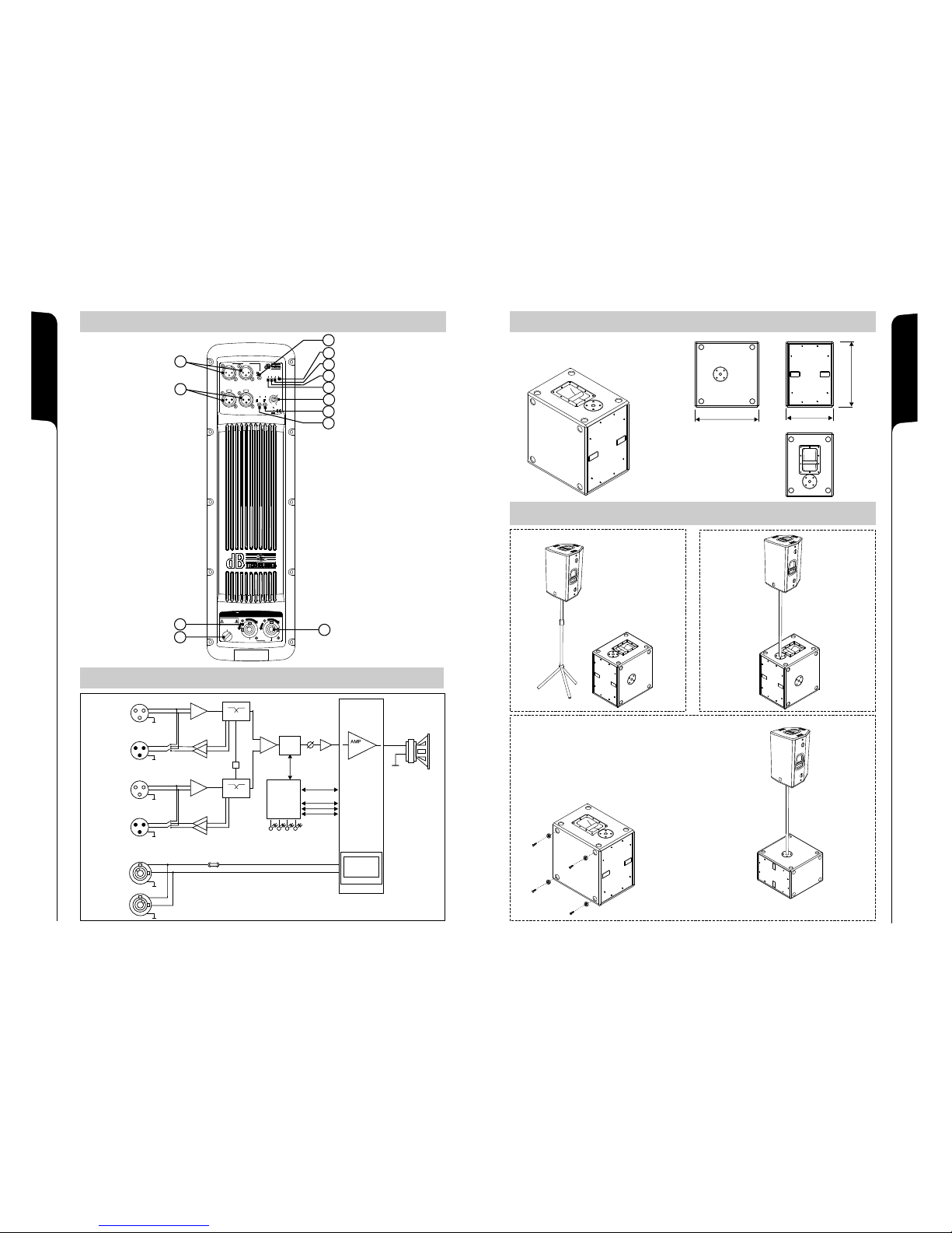
SCHEMA A BLOCCHI / BLOCK DIAGRAM
BLOCKSCHALTBILD / SCHEMAS FONCTIONNELS
14
13
DIMENSIONI / DIMENSIONS
ABMESSUNGEN / DIMENSIONS
500500
500500
370370
WOOFER 12”
BALANCED
CH2 INPUT
LINK
L
N
MAINS INPUT
Switching Mode
Power Supply
SMPS
MAINS
FUSE
L
N
MAINS OUTPUT
LINK
XOVER FREQ
uPROCESSOR
XOVER
Class D
®
DIGIPRO
XOVER
LIMITER
VOLUME
BALANCED
CH1 INPUT
LINK
XOVER FREQ
XOVER
XOVER
BALANCED
CH1 OUT
BALANCED
CH2 OUT
SE
PHA
LIMITER
SIGNAL
MUTE
READY
CONFIGURAZIONI e CONFIGURATION and
KONFIGURATIONEN und CONFIGURATIONS et
COLLEGAMENTI / CABLE CONNECTIONS
VERKABELUNG / CABLAGE
Nota: E’ possibile montare 4 piedi in gomma
sul fianco per utilizzo in appoggio (in dotazione)
Note: It is possible to mount 4 rubber feet on the
side for bookshelf use (provided)
Anmerkung: Es ist moglich, 4 Gummifu e auf die
Seite fur die Verwendung mit Stutze zu montieren
(die Fu e werden von der Baufirma geliefert)
Note: Il est possible de monter quatre pieds caoutchouc
sur le coté puor une utilisation en appui (en dotation)
ß
ß
12
PUSH
ON
MUTE
SGN
LIM
PHASE
90Hz
8
0dB
Mono
OUT 1 OUT 2
120Hz
0°
180°
XOVER
SUB-WOOFER
LEVEL
LINK
XOVER
BALANCED
INPUT 1
MONO
BALANCED
INPUT 2
0dB
Stereo
PUSH
8
7
6
5
4
3
1
2
9
10
11
13
“CAUTION”
TO PREVENT ELECTRICAL SHOCK
DO NOT REMOVE COVER
“AVIS”
RISQUE DE CHOCH ELECTRIQUE
NE PAS OUVRIR
LINK
MAINS INPUT
MAINS FUSE
ON
O
F
F
ON
F
O
F
OUTPUT
100-120V~ MAX 12A
220-240V~ MAX 16A
100-120V~ 50-60Hz
220-240V~ 50-60Hz
(T8A 250V~)
(T4A 250V~)
Internal voltage setup
MODULE POWER
CONSUMPTION
800W MAX
FIG.1 / ABB.1
Page 9

CONFIGURAZIONI e
CONFIGURATION and
KONFIGURATIONEN und
CONFIGURATIONS et
COLLEGAMENTI
CABLE CONNECTIONS
VERKABELUNG
CABLAGE
MONO
MIXER
MIXER
PUSH
ON
MUTE
SGN
LIM
PHASE
90Hz
8
0dB
Mono
OUT 1 OUT 2
120Hz
0°
180°
XOVER
SUB-WOOFER
LEVEL
LINK
XOVER
BALANCED
INPUT 1
MONO
BALANCED
INPUT 2
0dB
Stereo
PUSH
MIXER
ACTIVE SUBWOOFER
MIXER
PUSH
ON
MUTE
SGN
LIM
PHASE
90Hz
8
0dB
Mono
OUT 1 OUT 2
120Hz
0°
180°
XOVER
SUB-WOOFER
LEVEL
LINK
XOVER
BALANCED
INPUT 1
MONO
BALANCED
INPUT 2
0dB
Stereo
PUSH
STEREO
MONO
MIXER MIXER
MIXER
PUSH
ON
MUTE
SGN
LIM
PHASE
90Hz
8
0dB
Mono
OUT 1 OUT 2
120Hz
0°
180°
XOVER
SUB-WOOFER
LEVEL
LINK
XOVER
BALANCED
INPUT 1
MONO
BALANCED
INPUT 2
0dB
Stereo
PUSH
ACTIVE SPEAKER
MIXERMIXER
ACTIVE SPEAKER
ACTIVE SPEAKER
READY
MUTE
SIGNAL
LIMITER
SENSITIVITY
0dB
8
+4dB
MODE
-3dB
BALANCED
INPUT
LINK
OUT
PUSH
MIXER
READY
MUTE
SIGNAL
LIMITER
SENSITIVITY
0dB
8
+4dB
MODE
-3dB
BALANCED
INPUT
LINK
OUT
PUSH
READY
MUTE
SIGNAL
LIMITER
SENSITIVITY
0dB
8
+4dB
MODE
-3dB
BALANCED
INPUT
LINK
OUT
PUSH
PUSH
ON
MUTE
SGN
LIM
PHASE
90Hz
8
0dB
Mono
OUT 1 OUT 2
120Hz
0°
180°
XOVER
SUB-WOOFER
LEVEL
LINK
XOVER
BALANCED
INPUT 1
MONO
BALANCED
INPUT 2
0dB
Stereo
PUSH
PUSH
ON
MUTE
SGN
LIM
PHASE
90Hz
8
0dB
Mono
OUT 1 OUT 2
120Hz
0°
180°
XOVER
SUB-WOOFER
LEVEL
LINK
XOVER
BALANCED
INPUT 1
MONO
BALANCED
INPUT 2
0dB
Stereo
PUSH
PUSH
ON
MUTE
SGN
LIM
PHASE
90Hz
8
0dB
Mono
OUT 1 OUT 2
120Hz
0°
180°
XOVER
SUB-WOOFER
LEVEL
LINK
XOVER
BALANCED
INPUT 1
MONO
BALANCED
INPUT 2
0dB
Stereo
PUSH
ACTIVE SPEAKER
READY
MUTE
SIGNAL
LIMITER
SENSITIVITY
0dB
8
+4dB
MODE
-3dB
BALANCED
INPUT
LINK
OUT
PUSH
ACTIVE SUBWOOFER
ACTIVE SUBWOOFER
MONO
LINK
XOVER
LINK
XOVER
LINK
XOVER
LINK
XOVER
LINK
XOVER
ACTIVE SUBWOOFER
ACTIVE SUBWOOFER ACTIVE SUBWOOFER
16
15
CONFIGURAZIONI e
CONFIGURATION and
KONFIGURATIONEN und
CONFIGURATIONS et
COLLEGAMENTI
CABLE CONNECTIONS
VERKABELUNG
CABLAGE
 Loading...