

Page 1

MANUALE D’USO – Sezione 1
USER MANUAL - Section 1
Le avvertenze nel presente manuale devono essere osservate congiuntamente al “MANUALE D’USO - Sezione 2”.
The warnings in this manual must be observed together with the "User Manual - Section 2".
Page 2

EMI CLASSIFICATION
According to the standards EN 55103 this equipment is designed and suitable to operate in E3 (or lower E2, E1)
Electromagnetic environments.
FCC CLASS B STATEMENT ACCORDING TO TITLE 47, CHAPTER I,
SUBCHAPTER A, PART 15, SUBPART B
This device complies with part 15 of the FCC Rules. Operation is subject to the following two conditions: (1) This
device may not cause harmful interference, and (2) this device must accept any interference received, including
interference that may cause undesired operation.
WARNING
Make sure that the loudspeaker is securely installed in a stable position to avoid any injuries or damages to
persons or properties. For safety reasons di not place one loudspeaker on top of another without proper fastening
systems. Before hanging the loudspeaker check all the components for damages, deformations, missing or
damaged parts that may compromise safety during installation. If you use the loudspeakers outdoor avoid spots
exposed to bad weather conditions.
Contact dBTechnologies for accessories to be used with the speakers. dBTechnologies will not accept any
responsibility for damages caused by inappropiate accessories or additional devices.
DVA K5 Cod. 420120232 REV.1.0
2
Page 3

ITALIANO
ENGLISH
DVA K5 Cod. 420120232 REV.1.0
3
Page 4

Italiano
INDICE
1. INFORMAZIONI GENERALI ................................................................................................... 5
BENVENUTI! ........................................................................................................................ 5
PANORAMICA INTRODUTTIVA .......................................................................................... 5
RIFERIMENTI PER L’UTENTE ................................................................................................ 5
CARATTERISTICHE MECCANICHE ED ACUSTICHE ............................................................. 6
DIMENSIONI ............................................................................................................................................... 6
COPERTURA ACUSTICA ............................................................................................................................. 6
ACCESSORI ................................................................................................................................................. 6
CARATTERISTICHE DELLA SEZIONE DI AMPLIFICAZIONE E DI CONTROLLO ................... 7
SEZIONE DI INGRESSO, USCITA E CONTROLLO ........................................................................................ 8
SEZIONE DI ALIMENTAZIONE .................................................................................................................... 9
2. PRIMA ACCENSIONE ............................................................................................................ 10
CONTENUTO DELLA CONFEZIONE .................................................................................. 10
PREPARAZIONE ALL’UTILIZZO .......................................................................................... 10
UTILIZZO DI DBTECHNOLOGIES COMPOSER .................................................................. 11
MONTAGGIO DI DVA K5 IN CONFIGURAZIONE LINE-ARRAY ......................................... 12
COLLEGAMENTO E RILANCIO DELL’ALIMENTAZIONE............................................................................. 13
COLLEGAMENTO E RILANCIO DEL SEGNALE AUDIO ............................................................................. 14
CONFIGURAZIONE ED OTTIMIZZAZIONE IN LINE-ARRAY .............................................. 16
STACKED ............................................................................................................................ 17
FLOWN .............................................................................................................................. 17
3. ESEMPI DI UTILIZZO ED INSTALLAZIONE .......................................................................... 18
4. AGGIORNAMENTO DEL FIRMWARE .................................................................................. 21
5. RISOLUZIONE DEI PROBLEMI ............................................................................................. 22
6. SPECIFICHE TECNICHE DVA K5 ........................................................................................... 23
GENERALE ................................................................................................................................................ 23
DATI ACUSTICI .......................................................................................................................................... 23
AMPLIFICATORE ....................................................................................................................................... 23
PROCESSORE ............................................................................................................................................ 24
INTERFACCIA UTENTE .............................................................................................................................. 24
INGRESSI ED USCITE ................................................................................................................................ 24
SPECIFICHE DI ALIMENTAZIONE (ASSORBIMENTO) ............................................................................... 24
SPECIFICHE MECCANICHE ....................................................................................................................... 24
DVA K5 Cod. 420120232 REV.1.0
4
Page 5

Italiano
1. INFORMAZIONI GENERALI
BENVENUTI!
Grazie per aver acquistato un prodotto progettato e sviluppato in Italia da dBTechnologies! Questo modulo
line-array attivo a 3 vie racchiude in sé anni di esperienza ed innovazione nel campo della diffusione sonora, con
l’impiego di soluzioni d’avanguardia in campo acustico, elettronico e di ricerca sui materiali.
PANORAMICA INTRODUTTIVA
Il modulo line-array attivo DVA K5 è uno speaker a 3 vie nato per proseguire la strada di innovazione e qualità
professionale che caratterizzano la serie DVA. I 2 compression driver da 1” (bobina: 1.4”), 1 mid-range da
6.5” (bobina: 2”), 1 woofer da 8” (bobina: 2.5”) sono alloggiati in un cabinet in polipropilene, rinforzato da
una struttura metallica che ne ottimizza le prestazioni acustiche. Il DSP, che controlla l’amplicatore di nuova
generazione DIGIPRO G3, permette di congurare con semplicità e accuratezza il comportamento sonoro del
line-array in funzione di: numero di moduli, angolazione di montaggio fra un K5 e l’altro, distanza tra line-array
e pubblico. L’accoppiamento con i subwoofer della nuova serie DVA KS permette inne di soddisfare le esigenze
professionali di qualsiasi contesto e installazione.
Le caratteristiche più salienti del K5 sono:
• sezione di amplicazione potente e silenziosa, grazie al nuovo amplicatore in classe D DIGIPRO G3
che non necessita di ventilazione attiva
• SPL (di picco) di 129 dB
• trasduttori di alta qualità, progettazione acustica ottimizzata per l’utilizzo line-array, risposta in
frequenza full-range per l’utilizzo professionale
• dotazione di pin e staffe integrate, preforate e graduate, per un montaggio/smontaggio in
congurazione line-array facile, precisa ed immediato
• congurazione DSP veloce ed accurata tramite 2 rotary, per ottimizzare l’accoppiamento e la
compensazione delle alte frequenze
• Maneggevolezza e trasportabilità
• Peso contenuto, ottenuto grazie al box in prolipropilene e all’utilizzo di componenti con magnete al
neodimio
RIFERIMENTI PER L’UTENTE
Per utilizzare al meglio il vostro DVA K5 consigliamo di:
• leggere il manuale d’uso quick start presente nella confezione e questo manuale d’uso completo in
ogni sua parte e conservarlo per tutta la durata di vita del prodotto.
• registrare il prodotto sul sito http://www.dbtechnologies.com nella sezione “SUPPORTO”.
• conservare prova d’acquisto e GARANZIA (Manuale d’uso “sezione 2”).
DVA K5 Cod. 420120232 REV.1.0
5
Page 6
CARATTERISTICHE MECCANICHE ED ACUSTICHE
DIMENSIONI
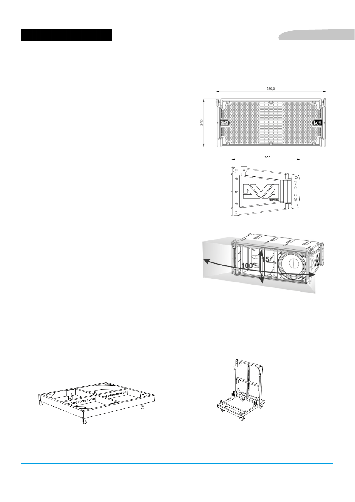
DVA K5 pesa solo 14,7 kg, e grazie alle misure contenute di 580
x 240 x 327 mm risulta maneggevole e facilmente trasportabile.
Il cabinet in polipropilene rinforzato presenta una struttura
interna metallica, che evita risonanze e vibrazioni indesiderate.
Le staffe integrate e i pin in dotazione sono di utilizzo
immediato e permettono di installare rapidamente, con la
corretta angolazione, un line-array con le caratteristiche
desiderate.
COPERTURA ACUSTICA
La copertura acustica, per riferimento, di un singolo modulo,
schematizzata in gura, è di 100 x 15°. L’effettivo coverage
si valuta di norma nell’utilizzo in line-array di più moduli. Si
consiglia di progettarlo con l’ausilio del software gratuito
dBTechnologies Composer.
Italiano
ACCESSORI
Per il montaggio, il trasporto e la protezione del sistema, sono
previsti come opzionali:
• Fly-bar DRK-10 e DRK-20
• Gancio DRK-HK per l’utilizzo con DRK-20
• Fly-bar DRK-20M motorizzato
• Kit di montaggio SRK-10 (l’utilizzo è riservato al
montaggio con il subwoofer DVA KS10)
• Staffa DWB-3 per l’nstallazione a muro e DSA-4 per
installazione a pavimento o su supporto piantana.
• Carrello per il trasporto da 1 a 6 moduli DT-6
• Flight case per contenere da 1 a 4 moduli DF-4
• Flight case integrato con carrello per contenere e trasportare no a 4 moduli DTF-4
• Sollevatore per diffusori in sospensione DRL-45
• Cavi di rilancio DCK-15, DPC-15, DAC 15, DPC-1000M, kit cavi DCK-15, DCK-45 e DCK-45 TypeB
Qua sotto sono mostrati a titolo di esempio un y-bar DRK-10 e lo
stesso y-bar montato su un carrello DT-6 per il solo trasporto.
Per ogni ulteriore informazione, fare riferimento al sito www.dbtechnologies.com e ai manuali relativi di ogni
singolo accessorio.
DVA K5 Cod. 420120232 REV.1.0
6
Page 7
Italiano
CARATTERISTICHE DELLA SEZIONE DI AMPLIFICAZIONE E DI CONTROLLO
L’amplicatore digitale di ultima generazione
DIGIPRO G3, in classe D, è caratterizzato da una
sezione di alimentazione con funzione di auto-range
particolarmente efciente. Il sistema è silenzioso, non
necessitando di un apparato di ventilazione.
Il controllo del sistema è afdato a un potente DSP che
permette di congurare in modo immediato e veloce il
line-array in qualsiasi contesto di utilizzo
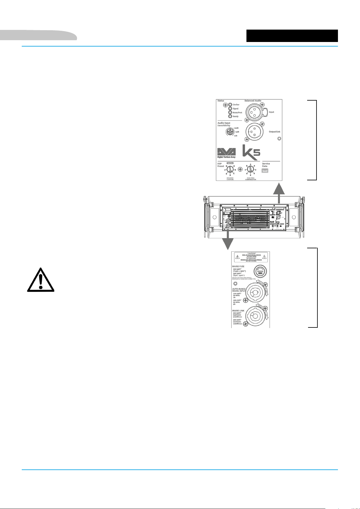
Il pannello del DIGIPRO G3 è caratterizzato da:
SEZIONE DI
INGRESSO, USCITA E
CONTROLLO
• Sezione di Ingresso, uscita e controllo
• Sezione di Alimentazione
ATTENZIONE!
• Proteggere il modulo dall’umidità.
• Non tentare in nessun modo di aprire
l’amplicatore.
• In caso di malfunzionamento,
interrompere immediatamente
l’alimentazione, scollegando il modulo
dalla rete, e contattare un riparatore
autorizzato.
SEZIONE DI
ALIMENTAZIONE
DVA K5 Cod. 420120232 REV.1.0
7
Page 8
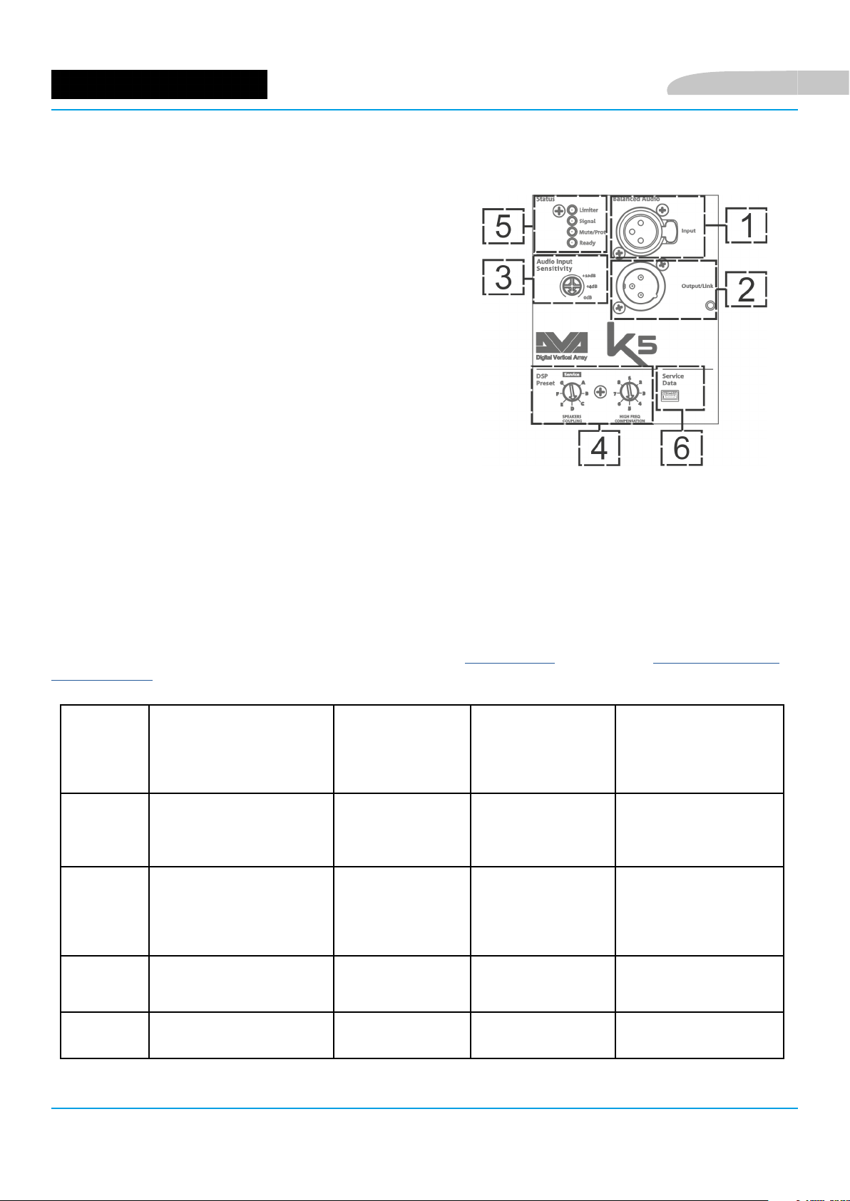
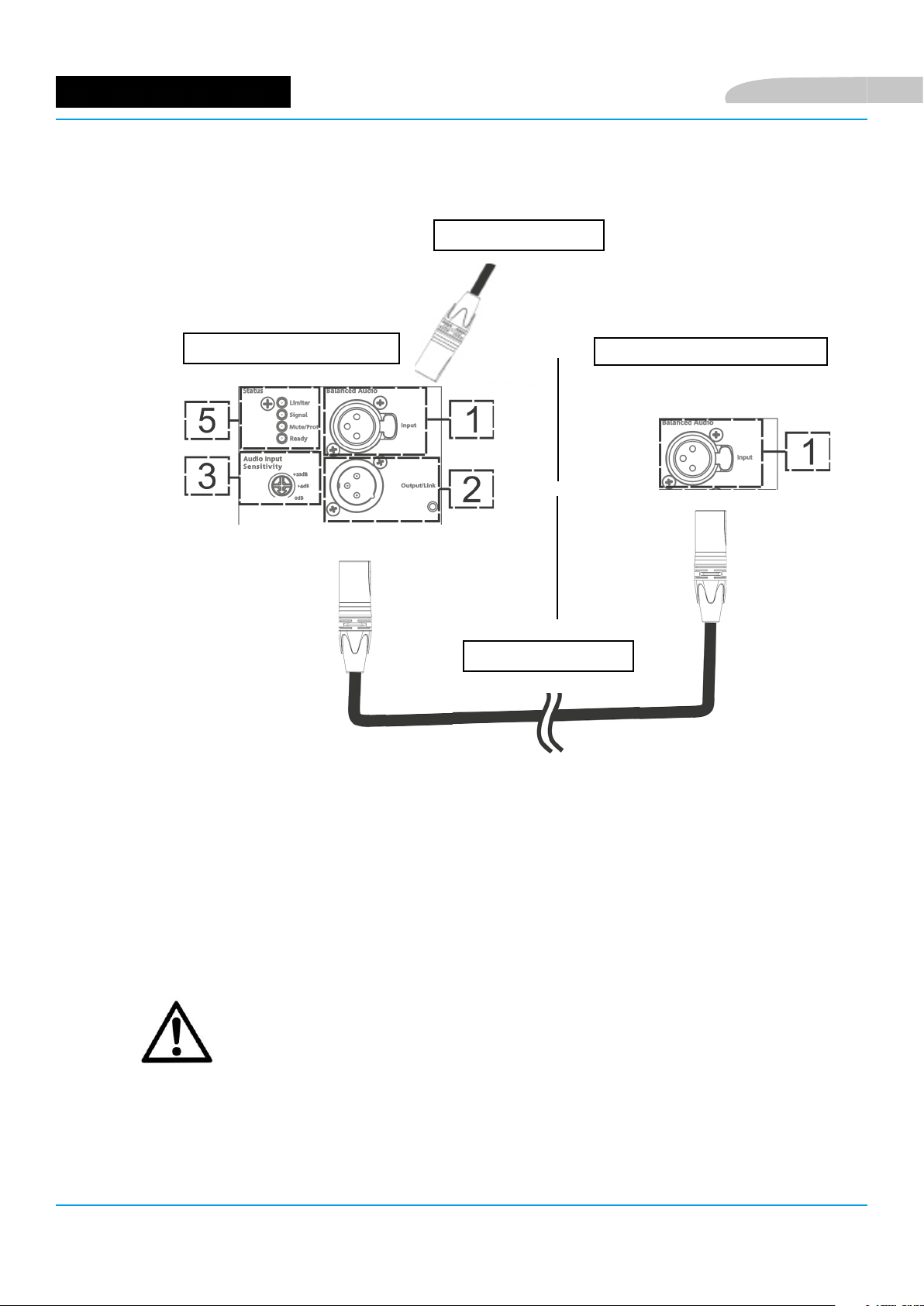
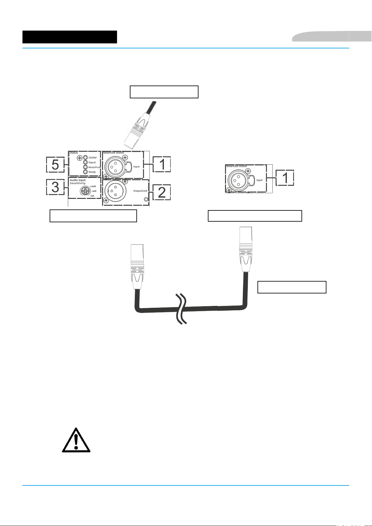
SEZIONE DI INGRESSO, USCITA E CONTROLLO
1. BALANCED AUDIO INPUT
Ingresso audio per cavo con connettore XLR
bilanciato.
2. LINK AUDIO OUTPUT/LINK
Uscita audio XLR bilanciata, che permette di inviare il
segnale ad un altro modulo.
3. AUDIO INPUT SENSITIVITY
Permette di variare la sensibilità di ingresso (non ha
effetto su un eventuale rilancio audio). Porre a 0 dB
prima del montaggio e relativo sollevamento del linearray.
4. ROTARY DI CONTROLLO DEL DSP PER IL SETTAGGIO IN LINE-ARRAY
Il rotary “SPEAKER COUPLING” e il rotary “HIGH FREQUENCY
COMPENSATION” permettono di ottimizzare il comportamento
acustico dei moduli K5 congurati in line-array. Confrontare anche il
paragrafo “CONFIGURAZIONE E OTTIMIZZAZIONE IN LINE-ARRAY”.
Italiano
5. LED DI SEGNALAZIONE (Limiter, Signal, Mute/Prot, Ready)
Durante il funzionamento normale dello speaker con segnale audio in ingresso, il LED Ready è acceso sso, il LED
Signal lampeggia indicando la presenza di segnale. Per ulteriori informazioni il funzionamento è schematizzato
nella gura sottostante.
6. PORTA USB “SERVICE DATA”
Tramite la porta mini-USB di tipo B è possibile aggiornare, il rmware del prodotto. Per ulteriori informazioni
consultare il sito http://www.dbtechnologies.com alla sezione “DOWNLOADS” ed il capitolo AGGIORNAMENTO
DEL FIRMWARE.
TIPO LED FASE DI ACCENSIONE
DELLO SPEAKER
IN FUNZIONE
NORMALE
WARNING
GENERICO
BLOCCO PER
ANOMALIA DELLO
SPEAKER
LIMITER SPENTO SPENTO, SI
ACCENDE SOLO
CON DISTORSIONE
SIGNAL
SPENTO LAMPEGGIO
IN PRESENZA DI
SEGNALE
LAMPEGGIO
MOMENTANEO
SEGNALAZIONE
NORMALE DI
AUDIO IN
INGRESSO
LAMPEGGIO CICLICO
CONTINUO
SPENTO
MUTE/
PROT
READY SPENTO ACCESO FISSO ACCESO FISSO SPENTO
DVA K5 Cod. 420120232 REV.1.0
ACCESO PER QUALCHE
SECONDO
SPENTO LAMPEGGIO
MOMENTANEO
Tabella di segnalazione dei LED
ACCESSO FISSO
8
Page 9

Italiano
SEZIONE DI ALIMENTAZIONE
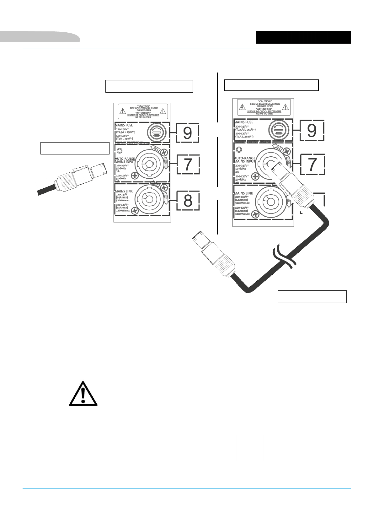
7. INGRESSO DI ALIMENTAZIONE “AUTO-RANGE MAINS INPUT”
Ingresso dell’alimentazione per cavo dotato di connettore tipo NEUTRIK®
powerCON®.
8. USCITA DI RILANCIO DELL’ ALIMENTAZIONE “MAINS LINK”
Uscita che permette il rilancio dell’alimentazione ad un secondo modulo
tramite cavo con connettore tipo NEUTRIK
9. FUSIBILE DI PROTEZIONE “MAINS FUSE”
Fusibile di rete.
ATTENZIONE!
• Il diffusore viene fornito con un fusibile già montato per
operare nel range 220-240 V. Se è necessario operare nel range
di tensione 100-120 V:
® powerCON®.
1. Disconnettere ogni connessione, compresa
l’alimentazione.
2. Attendere 5 minuti.
3. Sostituire il fusibile con quello fornito nella
confezione per il range 100-120 V.
• Non utilizzare il diffusore per un lungo periodo con il led di limiter acceso o
lampeggiante, che indica un funzionamento in condizioni di stress eccessivo.
• Utilizzare preferibilmente cavi dotati di connettori originali Neutrik®, di alta
qualità e integri.
DVA K5 Cod. 420120232 REV.1.0
9
Page 10
2. PRIMA ACCENSIONE
CONTENUTO DELLA CONFEZIONE
Il contenuto dell’imballo di DVA K5 è:
1. DVA K5
2. Quick start e documentazione relativa alla garanzia e alla sicurezza
3. Fusibile per il funzionamento nel range di tensione 100-120V
PREPARAZIONE ALL’UTILIZZO
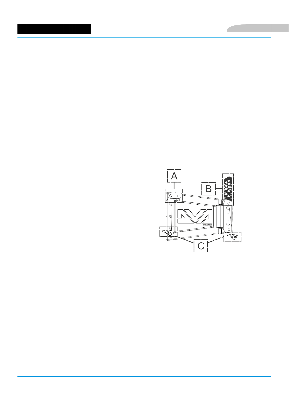
I componenti meccanici integrati di DVA K5 che si trovano su ogni lato dello speaker sono:
A - STAFFA ANTERIORE
B - STAFFA POSTERIORE PREFORATA E GRADUATA
C - PIN DI BLOCCAGGIO/SBLOCCAGGIO RAPIDO
Italiano
Prima dell’installazione, all’apertura della confezione ricordarsi di:
• Rimuovere le plastiche protettive dei pin laterali
• Togliere il sacchetto che contiene il fusibile
DVA K5 Cod. 420120232 REV.1.0
10
Page 11

Italiano
UTILIZZO DI DBTECHNOLOGIES COMPOSER
Il software dBTechnologies Composer, gratuitamente scaricabile dal sito
www.dbtechnologies.com, è lo strumento per la corretta progettazione di
sistemi audio consigliato per tutta la serie DVA K.
Suggerisce la soluzione automatica ottima per gli spazi indicati da
sonorizzare, indicando, tra gli altri parametri, l’angolazione dei moduli
del line-array per ottenere la copertura voluta. Permette poi una serie di
regolazioni manuali per perfezionare la congurazione in base ad eventuali
misure audio effettuate sul campo dall’operatore.
E’ inne lo strumento efcace per vericare l’installazione in sicurezza dei
moduli line-array, con una simulazione del comportamento statico dei y-bar.
Per ulteriori informazioni consultare il sito www.dbtechnologies.com nella
sezione DOWNLOADS.
DVA K5 Cod. 420120232 REV.1.0
11
Page 12

Italiano
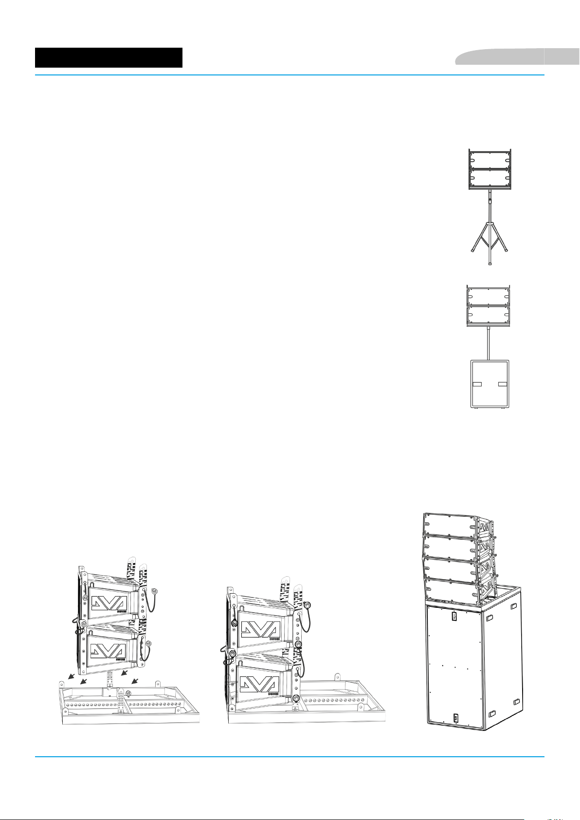
MONTAGGIO DI DVA K5 IN CONFIGURAZIONE LINE-ARRAY
Una volta denite le caratteristiche nali del line-array, in particolare l’angolazione necessaria, e il numero di
moduli, si può procedere al montaggio. Vericare che il rotary [3]
Audio Input Sensitivity di ogni modulo sia posto a 0 dB
(consigliabile nella maggior parte dei contesti).
1. Alzare le staffe frontali del modulo inferiore dopo aver
estratto i pin dal cabinet.
2. Inserire il modulo superiore allineando frontalmente le
staffe come mostrato.
3. Bloccare frontalmente i 2 moduli inserendo i relativi pin a
rilascio rapido. Il movimento a pressione/rilascio dei pin è
schematizzato nella gura sottostante.
4. Tenendo il modulo superiore sollevato sul retro, alzare le staffe posteriori del cabinet inferiore.
5. Inserire nelle sedi mostrate le staffe posteriori graduate all’angolazione desiderata. Fissarle
inserendo i relativi pin. L’angolo così installato fra i 2 moduli è segnalato da una linea che appare
immediatamente al di sotto della sede della staffa. Per esempio, nell’illustrazione mostrata,
l’angolazione è 0°. E’ ammessa un’inclinazione con passi di 1,5° nel range 0° - 6°, con passi di 2° nel
range 6° - 10° e con passi di 2,5° tra 10° e 15°.
DVA K5 Cod. 420120232 REV.1.0
12
Page 13
Italiano
COLLEGAMENTO E RILANCIO DELL’ALIMENTAZIONE
ALIMENTAZIONE
PRIMO MODULO DVA K5
SECONDO MODULO DVA K5
• Collegare l’alimentazione del primo modulo a AUTO-RANGE MAINS INPUT (7)
Utilizzare allo scopo un cavo con connettore powerCON® (non fornito).
• Rilanciare l’alimentazione dal primo al secondo modulo, collegando l’uscita MAINS
LINK OUTPUT (8) all’ingresso AUTO-RANGE MAINS INPUT (7), come illustrato.
• Ripetere l’operazione tra il secondo e il terzo modulo, e così via, no a collegare
tutti i moduli del line-array (vericare il massimo numero di moduli rilanciabili nel
capitolo SPECIFICHE TECNICHE DVA K5).
ATTENZIONE!
• Sulla targa dell’amplicatore di un modulo DVA K5 è indicato il valore
massimo e totale di corrente (e potenza) di un sistema di più moduli
con collegamento in rilancio.
• I cavi devono essere opportunamente dimensionati e la progettazione,
installazione e verica dell’impianto devono essere effettate
esclusivamente da personale qualicato. AEB industriale declina ogni
responsabilità in caso di utilizzo di cavi non idonei, non certicati
e non compatibili col corretto dimensionamento dell’impianto e le
normative in vigore per il Paese di utilizzo.
RILANCIO
DVA K5 Cod. 420120232 REV.1.0
13
Page 14
COLLEGAMENTO E RILANCIO DEL SEGNALE AUDIO
MIXER/LINEA
Italiano
PRIMO MODULO DVA K5
RILANCIO
• Collegare il cavo proveniente da MIXER/LINE all’ingresso BALANCED AUDIO (1) del
primo modulo del line array. Utilizzare allo scopo un cavo con connettore XLR (non
fornito). Per ulteriori informazioni sui cavi disponibili confrontare l’immagine nella
pagina seguente. Rilanciare il segnale tra il primo e il secondo modulo. A questo
scopo collegare l’uscita OUTPUT/LINK (2) all’ingresso BALANCED AUDIO (1) del
secondo come mostrato.
• Ripetere l’operazione tra il secondo e il terzo modulo, e così via, no a collegare tutti
i moduli del line-array.
SECONDO MODULO DVA K5
Italiano
ATTENZIONE!
• Utilizzare preferibilmente cavi dotati di connettori Neutrik®.
• Sostituire i cavi eventualmente danneggiati, per evitare
malfunzionamenti ed una scarsa qualità del suono.
DVA K5 Cod. 420120232 REV.1.0
14
Page 15

Italiano
DVA K5 Cod. 420120232 REV.1.0
15
Page 16

Italiano
CONFIGURAZIONE ED OTTIMIZZAZIONE IN LINE-ARRAY
L’utilizzo di un line-array comporta una serie di vantaggi in diversi contesti, in particolare:
• SPL omogeneo lungo la direttrice frontale degli speaker, effetto che si apprezza in particolare su
distanze medio-lunghe
• comportamento acustico direttivo, che permette di focalizzare in maniera precisa il suono sul pubblico,
evitando inutili dispersioni in ambienti ampi e riverberanti
L’ottimizzazione attuabile del line-array tiene conto del comportamento del sistema rispetto alla frequenza:
• all’aumentare della distanza dal line-array aumenta l’attenuazione dell’aria. Questo ha effetto in
particolare sulle alte frequenze.
• all’aumentare dell’angolazione degli elementi del line-array aumentano gli effetti legati
all’attenuazione delle onde sonore sulle frequenze medie.
• all’aumentare del numero di moduli del line-array la componente delle basse frequenze diventa
predominante
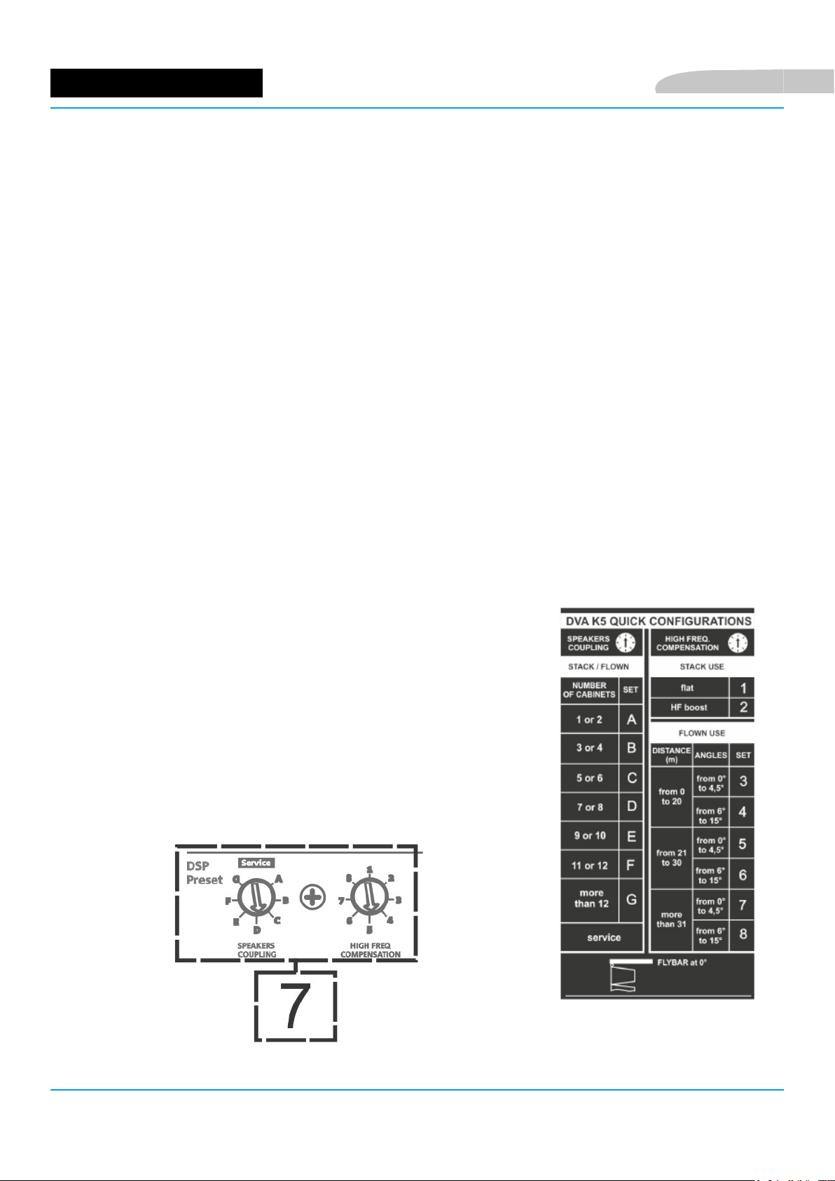
La congurazone acustica in line-array dei moduli DVA K5 può essere ottimizzata, grazie alle funzioni
di controllo gestite dal DSP. L’interfaccia per l’utilizzo è semplice e immediata: impiega due rotary della
sezione “DSP Preset” (4) e riporta l’etichetta di riferimento qui mostrata:
• Posizionare il rotary “SPEAKER COUPLING” in base al numero di
moduli impiegati nel line array. Questo rotary agisce sulle basse
frequenze e va impostato nella posizione:
• A - da 1 a 2 speaker
• B - da 2 a 4 speaker
• C - da 5 a 6 speaker
• D - da 7 a 8 speaker
• E - da 9 a 10 speaker
• F - da 11 a 12 speaker
• G - da 13 speaker in poi
DVA K5 Cod. 420120232 REV.1.0
16
Page 17

Italiano
• Posizionare il rotary “HIGH FREQUENCY COMPENSATION”
in base a tipo di installazione ed angolazione impostata nel
line-array. Questo rotary agisce sulla sezione delle medio-alte
frequenze e va impostato nella posizione:
STACKED
• 1 - installazione in uso stack (ad esempio su subwoofer
tramite l’apposito y-bar DRK-10/DRK-20), per
un’equalizzazione senza enfasi su una specica banda di
frequenze
• 2 - installazione in uso stack (ad esempio su subwoofer
tramite l’apposito y-bar DRK-10), per un’equalizzazione
che enfatizzi le alte frequenze
FLOWN
• 3 - installazione in uso appeso (own), con pubblico a
distanza di 0-20 m e angolazione fra ogni modulo da 0° a
4,5°
• 4 - installazione in uso appeso (own), con pubblico a
distanza di 0-20 m e angolazione fra ogni modulo da 6° a
15°
• 5 - installazione in uso appeso (own), con pubblico a
distanza di 21-30 m e angolazione fra ogni modulo da 0° a
4,5°
• 6 - installazione in uso appeso (own), con pubblico a
distanza di 21-30 m e angolazione fra ogni modulo da 6° a
15°
• 7 - installazione in uso appeso (own), con pubblico a
distanza maggiore di 31 m e angolazione fra ogni modulo
da 0° a 4,5°
• 8 - installazione in uso appeso (own), con pubblico a
distanza maggiore di 31m e angolazione fra ogni modulo
da 6° a 15°
DVA K5 Cod. 420120232 REV.1.0
17
Page 18

3. ESEMPI DI UTILIZZO ED INSTALLAZIONE
UTILIZZO SU STATIVO TREPPIEDE
DVA K5 può essere montato su treppiede opzionale standard con palo di diametro
35 mm. Per questo utilizzo è necessario l’accessorio DSA-4, si possono montare
no a 2 moduli e la distanza massima ammessa tra il primo elemento e terra è 130
cm (un piede della base deve essere in asse dietro l’amplicatore). DSA-4 permette
un’inclinazione massima di ± 5°. Per ogni ulteriore informazione fare riferimento alle
istruzioni di questo accessorio.
UTILIZZO SU SUBWOOFER CON PALO
L’utilizzo su un subwoofer DVA KS10, DVA KS20, o sub della serie DVA può avvenire
tramite palo di diametro 35 mm. Questo tipo di utilizzo prevede il montaggio ad
un’altezza massima di 85 cm tra la base dello speaker e il pavimento, prevedendo
no a 2 moduli DVA K5. Per questo scopo è necessario l’utilizzo di un accessorio
DSA-4 con inclinazione massima di 5° verso il basso degli speaker.
Italiano
POSIZIONAMENTO SU UN PIANO
DVA K5 può essere montato su un piano in appoggio, tramite i y-bar DRK-10/
DRK-20 (max. 6 moduli) e l’accessorio DSA-4 (massimo 3 moduli). Per ulteriori
approfondimenti si prega di fare riferimento ai manuali relativi.
CONFIGURAZIONE STACKED SU SUBWOOFER TRAMITE FLY-BAR
Il montaggio su subwoofer in stack può essere effettuata direttamente, attraverso
l’utilizzo di un y-bar DRK-10/DRK-20. Consultare i manuali relativi per ulteriori
informazioni.
DVA K5 Cod. 420120232 REV.1.0
18
Page 19
Italiano
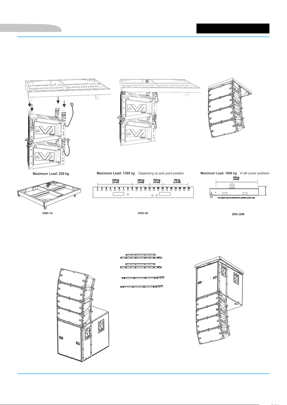
CONFIGURAZIONE FLOWN
DVA K5 può essere congurato own, utilizzando i y-bar DRK-10 o DRK-20 (o DRK-20M).
La correttezza del montaggio e i limiti di carico di sicurezza possono essere vericati con l’ausilio di
dBTechnologies Composer. Confrontare le etichette di sicurezza e le istruzioni relative dei y-bar per ulteriori
informazioni (DRK-10: 250 kg max, DRK-20: 1300 kg max in dipendenza dal punto di aggancio, DRK-20M: 1000
kg max).
CONFIGURAZIONE FLOWN O STACKED CON SUPPORTI LATERALI
DVA K5 può essere montato direttamente su un subwoofer DVA KS10 in con
gurazione stacked, oppure in congurazione own sotto a un DVA KS10, come
mostrato in gura, utilizzando l’accessorio opzionale SRK-10.
DVA K5 Cod. 420120232 REV.1.0
19
Page 20

Italiano
INSTALLAZIONE CON STAFFA A MURO
DVA K5 può essere montato a muro, tramite la staffa opzionale DWB 3. Gli ulteriori
accessori meccanici di montaggio della staffa non sono inclusi.
UTILIZZO DI UN SOLLEVATORE DRL-45
DVA K5 può essere sollevato utilizzando un sollevatore DRL-45. Il line-array da sollevare deve utilizzare il
un y-bar DRK-10 correttamente installato.
ATTENZIONE!
• Non utilizzare mai le maniglie, le staffe o altri elementi del diffusore per
sospendere direttamente i moduli o il sistema!
• In caso di utilizzo all’aperto è consigliabile ancorare il sistema per prevenire
eventali oscillazioni dovute al vento o agli agenti atmosferici
Al ne dell’utilizzo in sicurezza degli accessori, vericarne periodicamente funzionalità e integrità
prima dell’utilizzo.
Gli accessori devono essere utilizzati solo da personale qualicato! Assicurarsi che l’installazione sia
posizionata in modo stabile e sicuro per scongiurare ogni condizione di pericolo per persone, animali e/o cose. L’utilizzatore è tenuto a vericare le regolamentazioni e le leggi cogenti in materia di
sicurezza nel Paese in cui si utilizza il prodotto. Installare il prodotto attenendosi a quanto illustrato
in queste istruzioni.
DVA K5 Cod. 420120232 REV.1.0
20
Page 21

Italiano
4. AGGIORNAMENTO DEL FIRMWARE
È molto importante mantenere aggiornato il rmware del prodotto, per garantirne una piena funzionalità.
Controllare periodicamente il sito http://www.dbtechnologies.com nella sezione “DOWNLOADS”.
1. Scaricare ed installare USB BURNER MANAGER nella sezione “SOFTWARE & CONTROLLER” sul proprio
computer.
2. Scaricare il le .zip dell’ultimo rmware nella sezione “DOWNLOADS” relativa al proprio prodotto.
3. Collegare il prodotto al PC tramite un cavo USB (non fornito) con il connettore del tipo corretto (vedere questo
dettaglio nel capitolo CARATTERISTICHE DELLA SEZIONE DI AMPLIFICAZIONE E DI CONTROLLO).
4. Nella schermata dell’USB BURNER MANAGER, in alto a destra, selezionare “Apertura File”.
5. Selezionare il le del rmware precedentemente scaricato.
6. Seguire le operazioni mostrate a video.
7. Cliccare “AGGIORNA”.
DVA K5 Cod. 420120232 REV.1.0
21
Page 22

5. RISOLUZIONE DEI PROBLEMI
Il diffusore non si accende:
1. Vericare la corretta presenza dell’alimentazione a monte dell’impianto
2. Vericare che il cavo di alimentazione sia correttamente inserito.
3. Vericare eventuali collegamenti di rilancio dell’alimentazione.
Il diffusore si accende ma non emette nessun suono:
1. Vericare che i collegamenti in ingresso del segnale audio principale ed eventualmente di quello
rilanciato siano correttamente effettuati
2. Vericare che i cavi utilizzati non siano danneggiati
3. Vericare che il mixer o la sorgente audio sia accesa e mostri chiaramente la presenza di segnale in
ingresso al diffusore/line array.
4. Vericare che il livello della sensibilità Audio Input Sensitivity sia a un valore adeguato.
5. Vericare lo stato dei LED utilizzando la tabella presente nel capitolo CARATTERISTICHE DELLA SEZIONE
DI AMPLIFICAZIONE E DI CONTROLLO
Italiano
Il diffusore emette un suono distorto:
1. Vericare che il rotary Audio Input Sensitivity sia a 0 dB. Notare se il led di LIMITER è acceso, in questo
caso indica un funzionamento in condizioni di distorsione.
2. Vericare che i cavi utilizzati non siano danneggiati, nel qual caso sostituirli (un cavo danneggiato può
portare a perdita o alterazione del segnale).
3. Vericare le impostazioni del rotary DSP preset che inuiscono sulla risposta in frequenza in uscita. A tal
proposito consultare la sezione PRIMA ACCENSIONE.
DVA K5 Cod. 420120232 REV.1.0
22
Page 23

Italiano
6. SPECIFICHE TECNICHE DVA K5
GENERALE
Tipologia: Modulo line-array attivo a 3 vie
DATI ACUSTICI
Risposta in frequenza [± 3 dB]: 70 - 19000 Hz
Risposta in frequenza [± 3 dB]: 70 - 19000 Hz
Max SPL: 129 dB
Max SPL: 129 dB
HF: 2x 1” (Bobina:1.4”)
HF: 2x 1” (Voice coil:1.4”)
Tipo di trasduttore HF: Ceramico
Type HF: Ceramico
MF: 1x 6.5” (Bobina: 2”)
MF: 1x 6.5” (Voice coil: 2”)
LF: 1x 8” (Bobina: 2.5”)
LF: 1x 8” (Voice coil: 2.5”)
Tipo di trasduttore MF- LF: Neodimio
Type MF- LF: Neodimio
Frequenze di crossover: 340 Hz (Low/Mid), 1800 Hz (Mid/High)
Frequenze di crossover: 340 Hz (Low/Mid), 1800 Hz (Mid/High)
Direttività (HxV): 100°x15° (singolo modulo)
Direttività (HxV): 100°x15° (singolo modulo)
AMPLIFICATORE
Tipologia: Digipro® G3
Classe di amplicazione: Classe D
Potenza di amplicazione (Picco) 1000 W
Potenza di amplicazione (RMS): 500 W
Alimentazione: SMPS con PSU Auto-range
Connettore di alimentazione: (PowerCON® In/Link)
Tecnica di rareddamento: Convezione
DVA K5 Cod. 420120232 REV.1.0
23
Page 24
PROCESSORE
Controller interno: DSP 25/56 bit/48 kHz
Funzioni avanzate: Filtri FIR
Limiter: Peak, Termico
INTERFACCIA UTENTE
Italiano
Controlli:
Sensitivity control, 2 rotary a 8 posizioni (Coupling, Compensation)
Led di segnalazione: Limiter, Signal, Mute/prot, Ready
INGRESSI ED USCITE
Ingressi e rilanci di alimentazione: PowerCON® In/Link
Ingressi audio: 1x XLR IN bilanciato
USB (aggiornamento del rmware): 1x USB MINI tipo B
Uscite audio: 1x XLR link OUT bilanciato
SPECIFICHE DI ALIMENTAZIONE (ASSORBIMENTO)
Assorbimento a 1/8 della potenza in
condizioni medie di utilizzo (*):
Assorbimento a 1/3 della potenza in
condizioni massime di utilizzo (**):
Assorbimento con speaker acceso in
assenza di segnale (idle):
0,72 A / 76 W (230 V) - 1,22 A / 70 W (110 V)
1,25 A / 140 W (230 V) - 2,12 A / 144 W (110 V)
19 W
Corrente di inrush:
Corrente e potenze totali ammesse in
un sistema rilanciato :
* NOTA PER L’INSTALLATORE: Valori riferiti a 1/8 della potenza, in condizioni medie di funzionamento (programma musicale con clipping raro
o assente). Si consiglia per qualsiasi tipo di congurazione di considerarli i valori minimi di dimensionamento.
** NOTA PER L’INSTALLATORE: Valori riferiti a 1/3 della potenza, in condizioni pesanti di funzionamento (programma musicale con frequente
clipping e intervento del limiter). E’ consigliabile il dimensionamento secondo questi valori in caso di installazioni e tour professionali.
14 A / 3200 W max (230 V) - 11 A / 3200 W max (110 V)
18,3 A
SPECIFICHE MECCANICHE
Materiale: polipropilene rinforzato con metallo
Griglia: metallo - lavorazione CNC
Maniglie integrate
DVA K5 Cod. 420120232 REV.1.0
24
Page 25

Italiano
Predisposizioni di montaggio: Punti integrati nel cabinet
Montaggio diretto su palo: No, solo con accessori
Larghezza: 580 mm (22.83 inch.)
Altezza: 240 mm (9.45 inch.)
Profondità: 327 mm (12.87 inch.)
Peso: 14,7 kg (32,41 lbs.)
Le caratteristiche, specicazioni e aspetto dei prodotti sono soggetti a possibili cambiamenti senza previa
comunicazione. dBTechnologies si riserva il diritto di apportare cambiamenti o miglioramenti nel design o nelle
lavorazioni senza assumersi l’obbligo di cambiare o migliorare anche i prodotti precedentemente realizzati.
A.E.B. Industriale Srl
Via Brodolini, 8
Località Crespellano
40053 VALSAMOGGIA
BOLOGNA (ITALIA)
Tel +39 051 969870
Fax +39 051 969725
www.dbtechnologies.com
info@dbtechnologies-aeb.com
DVA K5 Cod. 420120232 REV.1.0
25
Page 26

English
TABLE OF CONTENTS
1. GENERAL INFORMATION .................................................................................................... 27
WELCOME! ....................................................................................................................... 27
PRELIMINARY OVERVIEW ................................................................................................ 27
USER REFERENCES ............................................................................................................ 27
MECHANICAL AND ACOUSTIC CHARACTERISTICS .......................................................... 28
DIMENSIONS ............................................................................................................................................ 28
ACOUSTIC COVERAGE ............................................................................................................................. 28
ACCESSORIES ........................................................................................................................................... 28
CHARACTERISTICS OF THE AMPLIFICATION AND CONTROL SECTION .......................... 29
INPUT OUTPUT AND CONTROL SECTION ............................................................................................... 30
POWER SUPPLY SECTION ........................................................................................................................ 31
2. FIRST SWITCH-ON ................................................................................................................ 32
PACKAGE CONTENTS ........................................................................................................ 32
PRELIMINARY OPERATIONS ............................................................................................. 32
USING DBTECHNOLOGIES COMPOSER ........................................................................... 33
INSTALLING DVA K5 IN A LINE-ARRAY CONFIGURATION .............................................. 34
POWER SUPPLY CONNECTION AND LINKING ........................................................................................ 35
INPUT CONNECTION AND EXTENSION .................................................................................................. 36
CONFIGURATION AND OPTIMISATION WITH DSP IN LINE-ARRAY ................................ 38
STACKED ............................................................................................................................ 39
FLOWN .............................................................................................................................. 39
3. INSTALLATION EXAMPLES .................................................................................................. 40
4. FIRMWARE UPDATES ........................................................................................................... 43
5. TROUBLESHOOTING ............................................................................................................ 44
6. TECHNICAL SPECIFICATIONS DVA K5 ................................................................................ 45
GENERAL .................................................................................................................................................. 45
ACOUSTIC DATA ....................................................................................................................................... 45
AMPLIFIER ................................................................................................................................................ 45
PROCESSOR .............................................................................................................................................. 46
USER INTERFACE ...................................................................................................................................... 46
INPUTS AND OUTPUTS ............................................................................................................................ 46
POWER SUPPLY SPECIFICATIONS ............................................................................................................ 46
DIMENSIONS ............................................................................................................................................ 46
DVA K5 Code 420120232 REV.1.0
26
Page 27

English
1. GENERAL INFORMATION
WELCOME!
Thank you for purchasing a product designed and developed in Italy by dBTechnologies! This 3-way active
line-array module is the result of years of experience and innovation on speakers, with the use of cutting-edge
solutions in the eld of acoustics, electronics and research on materials.
PRELIMINARY OVERVIEW
The DVA K5 active line-array module is a 3-way speaker designed by building upon the innovation and
professional quality of the DVA series. The 2 1” compression drivers (voice coil: 1.4”), 1 6.5” mid-range (voice coil:
2”), 1 8” woofer (voice coil: 2.5”) are housed in a polypropylene cabinet, reinforced by a metal frame optimising
its sound performance. The DSP, controlling the next-generation amplier DIGIPRO G3, allows to easily and
accurately congure the line-array sound behaviour according to: number of modules, angles of installation
between the K5 modules, distance between line-array and audience. When coupled with the new DVA KS series
subwoofers, nally, the module can meet all professional needs, in any context and installation.
The main features of K5 are:
• powerful and noiseless amplication section , thanks to the new DIGIPRO G3 D-class amplier,
requiring no active ventilation
• SPL (peak) of 129 dB
• high-quality transducers, sound design optimised for line-array use, full-range frequency response for
professional use
• equipped as standard with pins and built-in brackets, pre-drilled and graduated, for easy, accurate and
ready assembly/disassembly in a line-array conguration
• quick and accurate DSP conguration through 2 rotary encoders, optimising coupling and high
frequency compensation
• Easy to handle and transport
• Lightweight, thanks to the polypropylene box and to the use of neodymium magnet components.
USER REFERENCES
To get the most from your DVA K5 we recommend that you:
• thoroughly read the quick start user manual you will nd in the package and this manual, and keep it
throughout the product life.
• register the product on the site http://www.dbtechnologies.com, in the “SUPPORT” section
• keep the proof of purchase and the WARRANTY (User manual “section 2”).
DVA K5 Code 420120232 REV.1.0
27
Page 28

MECHANICAL AND ACOUSTIC CHARACTERISTICS
DIMENSIONS
DVA K5 only weighs 14.7 kg (32,41 lbs), and thanks to its small
dimensions - 580 x 240 x 327 mm - it can be handled and
transported easily.
The reinforced polypropylene cabinet has a metal inner frame,
preventing unwanted resonances and vibrations. The built-in
brackets and the standard pins are ready to use and allow to
quickly install, in the proper arrangement, a line-array having
the desired characteristics.
ACOUSTIC COVERAGE
The acoustic coverage, for reference purposes, of a single
module, as shown in the gure, is of 100 x 15°. The actual
coverage depends on the use of multiple modules in a linearray arrangement. We recommend that you design it with
the help of the free software dBTechnologies Composer.
English
ACCESSORIES
The following items are available as optional, for system
installation, transport and protection:
• DRK-10 and DRK-20 y-bars
• DRK-HK hook, to be used in conjunction with DRK-20
• DRK-20M motor-driven y-bar
• SRK-10 installation kit (for installation with DVA KS10
subwoofer only)
• Bracket DWB-3 for wall installation and DSA-4 for oor
or pedestal support installation.
• Trolley allowing to transport 1 to 6 DT-6 modules
• Flight case containing 1 to 4 DF-4 modules
• Built-in ight case with trolley, housing and allowing to transport up to 4 DTF-4 modules
• Lifting equipment for hanging speakers DRL-45
• Extension cables DCK-15, DPC-15, DAC 15, DPC-1000M, cable kit DCK-15, DCK-45 and DCK-45 TypeB
The gure below shows a sample DRK-10 y-bar and the y-bar in
question installed on a DT-6 trolley, for transport purposes only.
For any further information, please refer to the site www.dbtechnologies.com and to the relevant manuals of
each individual accessory.
DVA K5 Code 420120232 REV.1.0
28
Page 29

English
CHARACTERISTICS OF THE AMPLIFICATION AND CONTROL SECTION
The D-class next generation amplier DIGIPRO G3
features a power supply section with a particularly
efcient auto-range function. The system is noiseless, as
it doesn't require a ventilation system.
The system is controlled by a powerful DSP allowing to
readily and quickly congure the line-array in any usage
context
The DIGIPRO G3 panel consists of:
CONTROL SECTION
INPUT, OUTPUT AND
• Input Output and Control section
• Power supply section
ATTENTION!
• Protect the module from humidity.
• Never try to open the amplier.
• In case of malfunction, immediately cut
off the power supply, by disconnecting
the module from the mains, then contact
an authorised repairman.
SECTION
POWER SUPPLY
DVA K5 Code 420120232 REV.1.0
29
Page 30

INPUT OUTPUT AND CONTROL SECTION
1. BALANCED AUDIO INPUT
Audio input for a cable equipped with a
balanced XLR connector.
2. LINK AUDIO OUTPUT
Balanced XLR output, allowing to send the input audio signal to
another amplied speaker.
3. AUDIO INPUT SENSITIVITY
It allows to vary the input sensitivity. Before turning on the unit,
make sure that the Audio Input Sensitivity is turned to 0 dB.
4. DSP CONTROL ROTARY ENCODERS FOR IN LINE-ARRAY SETTING
The “SPEAKER COUPLING” rotary encoder and the “HIGH FREQUENCY
COMPENSATION” rotary encoder allow to optimise the sound
behaviour of the K5 modules congured in a line-array. Also refer to
paragraph “IN LINE-ARRAY CONFIGURATION AND OPTIMISATION”.
English
5. LEDs (Limiter, Signal, Mute/Prot, Ready)
During normal speaker operation with audio input signal, the Ready LED is steadily on, the Signal LED blinks
indicating the signal presence.
6. "SERVICE DATA" USB PORT
The type B mini-USB B port allows to update the product rmware. For further information, please refer to
the Web site (see DOWNLOADS section and )
LED TYPE SPEAKER
SWITCH-ON
LIMITER OFF OFF, IT STARTS
NORMAL
OPERATION
BLINKING ONLY
GENERIC
WARNING
TEMPORARY
BLINKING
STOP DUE TO
SPEAKER MALFUNCTION
ONGOING CYCLIC BLINKING
IN DISTORSION
CASE
SIGNAL OFF BLINKING WITH
SIGNAL
NORMAL INPUT
AUDIO INDICA-
OFF
TION
MUTE/
PROT
ON FOR A
FEW SECONDS
OFF TEMPORARY
BLINKING
STEADILY ON
READY OFF STEADILY ON STEADILY ON OFF
LEDs table
DVA K5 Code 420120232 REV.1.0
30
Page 31

English
POWER SUPPLY SECTION
7. “AUTO-RANGE MAINS INPUT” POWER SUPPLY INPUT
Power supply input for cable equipped with NEUTRIK® powerCON® connector.
8. “MAINS LINK” POWER SUPPLY LINKING OUTPUT
Output allowing to extend the power supply to a second module through a
cable equipped with a NEUTRIK
9. “MAINS FUSE” PROTECTION FUSE
Mains fuse
ATTENTION!
• The speaker is supplied with a pre-installed fuse
designed to operate within the 220-240 V range.
Should it need to operate within the 100-120 V
1. Disconnect all connections,
including the power supply one.
2. Wait for 5 minutes.
3. Replace the fuse with the one
included in the package for the
® powerCON connector.
• Only use cables equipped with high-quality genuine Neutrik® connectors.
• Never use the speaker for a prolonged time while the limiter LED is on or blinking, indicating
the equipment is running under excessive stress conditions
DVA K5 Code 420120232 REV.1.0
31
Page 32

2. FIRST SWITCH-ON
PACKAGE CONTENTS
The DVA K5 package includes:
1. DVA K5
2. Quick start and warranty/safety-related documents
3. Fuse to be installed if the system is to operate within the 100-120V range
PRELIMINARY OPERATIONS
The DVA K5 built-in mechanical components installed on each speaker side are:
A - FRONT BRACKET
B - PRE-DRILLED AND GRADUATED REAR BRACKET
C - QUICK COUPLING/RELEASE PIN
English
Before installing the equipment, when opening the package remember to:
• Remove the plastic protections from the side pins
• Remove the bag containing the fuse
DVA K5 Code 420120232 REV.1.0
32
Page 33
English
USING DBTECHNOLOGIES COMPOSER
The software dBTechnologies Composer, which can be downloaded for free
from www.dbtechnologies.com, is a tool allowing users to properly design
their audio system, recommended for all the equipment belonging to the
DVA K series.
It proposes the optimum solution for the selected areas, specifying the linearray module angle required to obtain the proposed coverage.
It also allows to effectively check the safe installation of the line-array
modules, by simulating the static behaviour of the y-bars.
For further information please refer to the DOWNLOADS section of
www.dbtechnologies.com.
DVA K5 Code 420120232 REV.1.0
33
Page 34

English
INSTALLING DVA K5 IN A LINE-ARRAY CONFIGURATION
After dening the nal line-array characteristics, and the required angle in particular, you can proceed with
the installation. Please check that Audio Input Sensitivity is set on 0 dB
(common usage).
1. Raise the front brackets of the lower module after
extracting the pins from the cabinet.
2. Insert the upper module, aligning the brackets on the front
side as shown.
3. Lock the 2 modules on the front side by inserting the
relevant quick-release pins. The pin pressing/release
movement is shown in the gure below.
4. While holding the upper module raised, raise the brackets on the rear side of the lower cabinet.
5. Insert the graduated rear brackets into the specied seats, at the desired angle. Fix them by inserting
the relevant pins. The angle between the 2 installed modules is indicated by a line appearing just
below the conguration. In the gure below, for example, the angle is 0°. Inclination can be set in
steps of 1.5° in the 0° - 6° range, in steps of 2° in the 6° - 10° range and in steps of 2.5° in the 10° to 15°
range.
DVA K5 Code 420120232 REV.1.0
34
Page 35

English
POWER SUPPLY CONNECTION AND LINKING
POWER SUPPLY
FIRST DVA K5 MODULE
SECOND DVA K5 MODULE
LINK
• Connect the rst module power supply to AUTO-RANGE MAINS INPUT (7). For this
purpose, use a cable equipped with a powerCON connector (not included in the supply).
• Extend the power supply from the rst to the second module, by connecting the MAINS
LINK OUTPUT (8) to the AUTO-RANGE MAINS INPUT (7), as shown in the gure.
• Repeat the operation between the second and the third module, and so on, until all
line-array modules are connected (check the maximum number of power supply links in
Technical Specications).
ATTENTION!
• The amplier nameplate of a DVA K5 module species the maximum
and total current (and power) value of a multiple module system with
extension connections.
• The cables must be properly sized and design, installation and system
testing should exclusively be performed by qualied personnel. AEB
Industriale accepts no responsibility in case of use of cables which
are unsuitable, non-certied, non-compatible with the correct system
sizing and the regulations in force in the country of use.
DVA K5 Code 420120232 REV.1.0
35
Page 36
INPUT CONNECTION AND EXTENSION
MIXER/LINE
English
SECOND DVA K5 MODULEFIRST DVA K5 MODULE
LINK
• Connect the cable from MIXER/LINE to the BALANCED AUDIO (1) input of the rst
line array module. For this purpose, use a cable equipped with an XLR connector (not
included in the supply). For further information about the cables that are available
please refer to the picture at p. 37.
• Extend the signal between the rst and the second module. To this purpose connect
the OUTPUT/LINK (2) output to the BALANCED AUDIO (1) input of the second module.
• Repeat the operation between the second and the third module, and so on, until all
line-array modules are connected.
ATTENTION!
• Only use cables equipped with Neutrik® connectors
• Replace any damaged cables, to avoid malfunctions and
poor sound quality.
DVA K5 Code 420120232 REV.1.0
36
Page 37

English
DVA K5 Code 420120232 REV.1.0
37
Page 38
English
CONFIGURATION AND OPTIMISATION WITH DSP IN LINE-ARRAY
The use of a line-array provides multiple benets in various contexts; in particular:
• Homogeneous SPL along the speaker front direction; the effect is particularly noticeable over medium
to long distances
• directive sound behaviour, allowing to accurately focus the sound on the audience, avoiding
unnecessary dispersions in large and reverberating environments
The line-array optimisation takes into account the system behaviour with respect to the frequency:
• as distance from the line-array increases, air attenuation increases as well. This particularly applies to
high frequencies.
• as the angle of the line-array components increases, the effects associated with soundwave
attenuation at medium frequencies increase as well.
• as the number of line-array modules increases the low frequency components becomes dominant
The DSP-managed control functions allow to optimise the line-array sound conguration of the DVA K5
modules. The user interface is simple and intuitive. It includes two rotary encoders installed in the “DSP
Preset” (7) section and the reference label shown below:
• Turn the “SPEAKER COUPLING” rotary encoder to set the number
of modules included in the line array. This rotary encoder
affects the low frequencies and must be turned to the following
position:
• A - 1 to 2 speakers
• B - 2 to 4 speakers
• C - 5 to 6 speakers
• D - 7 to 8 speakers
• E - 9 to 10 speakers
• F - 11 to 12 speakers
• G - 13 speakers and beyond
DVA K5 Code 420120232 REV.1.0
38
Page 39

English
• Turn the “HIGH FREQUENCY COMPENSATION” rotary encoder
according to the type of installation and angle set in the linearray. This rotary encoder affects the medium to high frequency
sections and must be turned to the following position:
STACKED
• 1 - installation in a stacked conguration (for example on
subwoofer through the specially designed DRK-10 y-bar), for an
equalisation with no emphasis over the whole frequency range.
• 2 - installation in a stacked conguration (for example on
subwoofer through the specially designed DRK-10 y-bar), for an
equalisation emphasising high frequencies
FLOWN
• 3 - installation in a own conguration, with the audience
0-20 m away and an angle between each module ranging
between 0° and 4.5°
• 4 - installation in a own conguration, with the audience
0-20 m away and an angle between each module ranging
between 6° and 15°
• 5 - installation in a own conguration, with the audience
21-30 m away and an angle between each module ranging
between 0° and 4.5°
• 6 - installation in a own conguration, with the audience
21-30 m away and an angle between each module ranging
between 6° and 15°
• 7 - installation in a own conguration, with the audience
over 31 m away and an angle between each module
ranging between 0° and 4.5°
• 8 - installation in a own conguration, with the audience
over 31m away and an angle between each module
ranging between 6° and 15°
DVA K5 Code 420120232 REV.1.0
39
Page 40
3. INSTALLATION EXAMPLES
INSTALLATION ON TRIPOD STAND
DVA K5 can be installed on an optional standard tripod with a pole having a
diameter of 35 mm. The DSA-4 accessory is required for this installation; you can
mount up to 2 modules and the maximum permitted distance between the rst
element and the ground is 130 cm. DSA-4 allows a maximum inclination of ± 5°.
For further information, please refer to the instructions of this accessory.
INSTALLATION ON SUBWOOFER WITH POLE
To install the modules on a subwoofer DVA KS10, DVA KS20, DVA S10DP or
DVA S1518N you must use a pole having a diameter of 35 mm. For this type of
installation, the distance between the speaker base and the oor must not exceed
85 cm, and you can mount up to 2 DVA K5 modules. To this purpose you need to
use a DSA-4 accessory, and the downward inclination of the speakers must not
exceed 5°.
English
INSTALLATION ON A FLAT SURFACE
DVA K5 can be installed on a at surface, using the DRK-10/DRK-20 y-bars (max 6
modules) and the DSA-4 (max. 3 modules) accessory For further information please
refer to the relevant manuals.
STACKED INSTALLATION ON SUBWOOFER THROUGH A FLY-BAR
Stacked modules can be directly installed on a subwoofer, using a DRK-10/DRK-20
y-bar. For further information please refer to the relevant manuals.
DVA K5 Code 420120232 REV.1.0
40
Page 41

English
FLOWN INSTALLATION
DVA K5 can be installed in a own conguration, using the DRK-10 or DRK-20 (or DRK-20M) y-bars.
Proper installation and safety load limits can be veried with the help of dBTechnologies Composer. For further
information please refer to the safety labels and to the relevant instructions for the y-bars (DRK-10: 250 kg
max, DRK-20: 1300 kg max, depending on the connecting point, DRK-20M: 1000 kg max).
EnglishEnglish
FLOWN OR STACKED INSTALLATION WITH SIDE SUPPORTS
DVA K5 can be directly mounted on a DVA KS10 subwoofer in a stacked
conguration, or in a own conguration under a DVA KS10, as shown in the
gure, using the optional SRK-10 accessory.
DVA K5 Code 420120232 REV.1.0
41
Page 42

INSTALLATION WITH WALL BRACKET
DVA K5 can be wall-mounted, using the optional DWB 3 bracket. The further
mechanical accessories required for bracket installation are not included.
USE OF DRL-45 LIFTING EQUIPMENT
DVA K5 can be lifted using DRL-45 lifting equipment. The line-array to be lifted must use a properly
installed DRK-10 y-bar.
English
ATTENTION!
• Never use the speaker handles, brackets or other components to hang the
system!
• When used outdoors, anchor the speaker to prevent any oscillations due
to atmospheric agents and wind.
For safe use of accessories, periodically check their functionality and integrity before
using them.
Accessories must be used by qualied personnel only! Make sure the installation is stable
and safe, to avoid any hazard to people, animals and/or property. The user must verify the
binding safety regulations and laws in force in the Country where the product is being
used. When installing the product follow the instructions provided herein.
DVA K5 Code 420120232 REV.1.0
42
Page 43

English
4. FIRMWARE UPDATES
IT IS very important to keep product rmware updated to the latest version to ensure full performance. Please
check site http://www.dbtechnologies.com for updates under section “DOWNLOADS” periodically.
1. Download USB BURNER MANAGER from section “SOFTWARE & CONTROLLER” of the dBTechnologies site.
2. Download the .zip le with the last rmware from section “DOWNLOADS” for your product
3. Connect the product to the PC by means of a USB cable (not supplied) featuring the right connector detail is
contained in section FEATURES OF THE AMPLIFIER AND CONTROL SECTIONS
4. In the top right corner of the USB BURNER MANAGER screen, select “File Opening”.
5. Select the rmware le you have downloaded previously (ensure that it is suitable for your operating system).
6. Follow the on-screen instructions.
7. Click UPDATE.
DVA K5 Code 420120232 REV.1.0
43
Page 44

5. TROUBLESHOOTING
The speaker doesn't turn on:
1. Check that the power supply upstream of the system is working properly
2. Check that the power cord is properly plugged
3. Check that the ON/OFF selector is turned to “I”.
The speaker turns on but it doesn't output any sound:
1. Check that the input connections of the main audio signal and of the auxiliary one, if any, have been
performed properly
2. Check that the cables in use are not damaged
3. Check that the mixer or the audio source are on and that they clearly indicate the presence of an
output signal to the speaker.
4. Check that the level of the main audio volume and of the auxiliary one, if any, are set to an appropriate
value.
English
The speaker outputs a distorted sound:
1. Check that the Audio Input Sensitivity rotary encoder is set on the correct value (0 dB). It should be
noted that if the LIMITER LED is on, it indicates the speaker is operating under distorting conditions.
2. Check that the cables in use are not damaged; should that be the case, replace them (a damaged cable
may result in a signal loss or alteration).
3. Check that the LINE-MIC switch matches the actual input connection.
4. Check the settings of the rotary encoder DSP preset affecting the output frequency response. To this
purpose please refer to section FIRST SWITCH-ON.
DVA K5 Code 420120232 REV.1.0
44
Page 45

English
6. TECHNICAL SPECIFICATIONS DVA K5
GENERAL
Type: 3-way active line-array module
ACOUSTIC DATA
Frequency response [± 3 dB]: 70 - 19000 Hz
Max SPL: 129 dB
HF: 2x 1” (Voice coil:1.4”)
Type HF: Ceramic
MF: 1x 6.5” (Voice coil: 2”)
LF: 1x 8” (Voice coil: 2.5”)
Type MF- LF: Neodymium
Crossover frequency: 340 Hz (Low/Mid), 1800 Hz (Mid/High)
Directivity (HxV): 100°x15° (single module)
AMPLIFIER
Type: Digipro® G3
Amplication class: D class
Amplication power (Peak) 1000 W
Amplication power(RMS): 500 W
Power supply: SMPS with PSU Auto-range
Power supply connector: (PowerCON In/Link)
Cooling technique: Convection
DVA K5 Code 420120232 REV.1.0
45
Page 46

PROCESSOR
Internal controller: DSP 25/56 bit/48 kHz
Advanced functions: FIR lters
Limiter: Peak, ermal
USER INTERFACE
Controls: Sensitivity control, 2 8-position rotaries
Led Limiter, Signal, Mute/prot, Ready
INPUTS AND OUTPUTS
Power supply inputs and links: PowerCON In/Link
Audio input: 1x XLR IN, balanced
English
USB: 1x USB MINI, type B
Audio output: 1x XLR link OUT, balanced
POWER SUPPLY SPECIFICATIONS
Draw at 1/8 of full power in average
use conditions (*):
Draw at 1/3 of full power in maximum
use conditions (**):
Draw with speaker turned on without
signal (idle): :
Inrush current:
Total current and power allowed in
daisy-chain conguration:
* INSTALLER NOTES: The values refer to 1/8 of full power, in average operating conditions (music program with infrequent or no clipping). It
is recommended to consider them the minimum sizing values for any type of conguration.
** INSTALLER NOTES: The values refer to 1/3 of full power, in heavy operating conditions (music program with frequent clipping or activation
of the limiter). We recommend sizing according to these values in case of professional installations and tours.
0,72 A / 76 W (230 V) - 1,22 A / 70 W (110 V)
1,25 A / 140 W (230 V) - 2,12 A / 144 W (110 V)
19 W
18.3 A
14 A / 3200 W max (220 V) - 11 A / 3200 W max (110 V)
DIMENSIONS
Material: metal-reinforced polypropylene
Grid: NC machining
Handles built-in
DVA K5 Code 420120232 REV.1.0
46
Page 47

English
Connecting points: built into the cabinet
Direct installation on pole: No, with accessories only
Width: 580 mm (22.83 inch.)
Height: 240 mm (9.45 inch.)
Depth: 327 mm (12.87 inch.)
Weight: 14,7 kg (32,41 lbs)
The characteristics, specications and appearance of the products are subject to change without warning.
dBTechnologies reserves the right to make any change or improvement to product design or manufacturing
without undertaking any obligation to also change or improve the previously manufactured products.
A.E.B. Industriale Srl
Via Brodolini, 8
Località Crespellano
40053 VALSAMOGGIA
BOLOGNA (ITALIA)
Tel +39 051 969870
Fax +39 051 969725
www.dbtechnologies.com
info@dbtechnologies-aeb.com
DVA K5 Code 420120232 REV.1.0
47
 Loading...