

Page 1
ISTRUZIONI DI UTILIZZO DSA-ViOL208
DSA-ViOL208 INSTRUCTIONS
DSA-ViOL208
Accessorio
Accessory
DSA-VIOL208 VIO-L208
Prodotto
Product
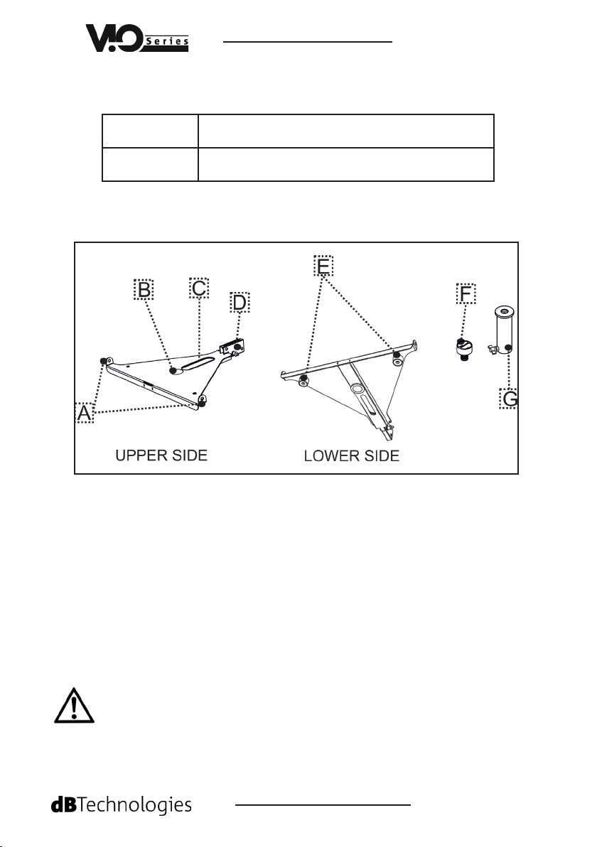
1.Contenuto della confezione
Packing content
A - n°2 AGGANCI PER VIO-L208
n°2 ANCHORAGE SYSTEM FOR VIO-L208
B - n°1 FORO PER IL FISSAGGIO DELL’ADATTATORE [G]
n°1 HOLE FOR FASTENING THE ADAPTOR [G]
C - n°1 ASOLA DI POSIZIONAMENTO PER SUBWOOFER
n°1 POSITIONING SLOT FOR SUBWOOFER
D - n°1 STAFFA POSTERIORE DI FISSAGGIO A 3 POSIZIONI
n°1 FASTENING REAR BRACKET IN 3 POSITIONS
E - n°2 PIEDI PLASTICI DI APPOGGIO SU SUBWOOFER
n°2 RUBBER FEET FOR ON-SUBWOOFER MOUNTING
F - n°1 PERNO FILETTATO DI FISSAGGIO
n°1 THREADED FASTENING PIN
G - n°1 ADATTORE PER POLE MOUNT CON VOLANTINO DI SERRAGGIO
n°1 POLE MOUNT ADAPTER WITH LOBE KNOB
L’installazione di DSA-VIOL208 deve essere effettuata da personale esperto. I tipi di utilizzo ammessi sono 3 e
sono illustrati qui di seguito. Non sono ammessi utilizzi differenti da quanto descritto. A pagina 4 sono anche
riportati i limiti massimi per installazione libera. Se si eccedono tali limiti è obbligatorio un ssaggio addizionale
con cinghie o mezzi meccanici (non forniti).
Only qualied personnel may use the DSA-VIOL208! The admitted uses are 3 and they are illustrated in the next
pages. Different uses are not allowed. The maximum limit in installation is shown in the table at page 4. If
you need to exceed those limits it is mandatory to use additional mechanical systems and fastening belts (not
supplied).
FOT000098 REV.1.0
Page 2
2. Montaggio su palo
2. On pole mounting
DSA-ViOL208
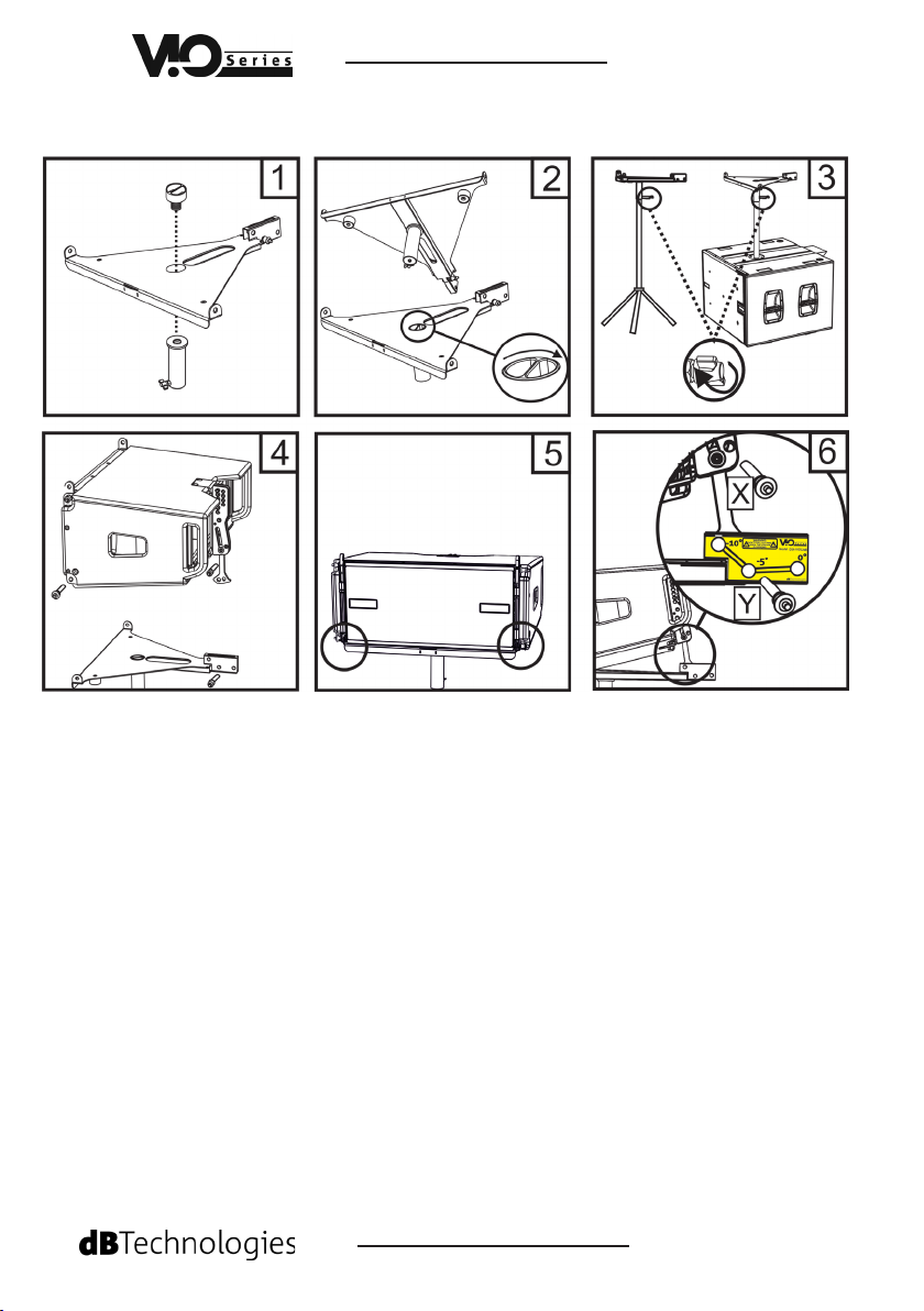
• Fissare a DSA-VIOL208 il pole-mount [G] con il perno di ssaggio [F] (gure 1-2).
• Assicurare il pole-mount allo stand con treppiede / palo su sub stringendo la vite a
farfalla indicata (g. 3).
• Estrarre i pin indicati e agganciare il modulo VIO-L208 sul lato frontale (g. 4-5)
• Sul retro di VIO L-208, estrarre la staffa mobile completamente, inserire il pin [X]
come mostrato e agganciare la staffa con DSA-VIOL208 nella posizione prescelta
inserendo il pin [Y]. Gli angoli ammessi, mostrati dall’etichetta, sono: 0°
-5° oppure -10° (g. 6).
• Aggiungere altri moduli VIO-L208 (vedi il paragrafo “CONFIGURAZIONI AMMESSE” in
ultima pagina) secondo le istruzioni relative al modulo line-array.
• Fasten the pole-mount [G] to DSA-VIOL208 using the fastening pin [F] (pic. 1-2).
• Fasten the pole-mount to the tripode stand / pole on sub, screwing the lobe knob [F]
(g. 3).
• Extract the pins as shown and mount the VIO-L208 on the front site (pic. 4-5).
• On the rear site of VIO L-208, fully extract the bracket, insert the [X] pin as shown
and fasten the bracket in DSA-VIOL208 in the choosen position, inserting the
[Y] pin. The shown splay angles, as described in the label, are: 0°, -5°, -10° (pic. 6).
• Add futher VIO-L208 modules (see the paragraph “ADMITTED CONFIGURATIONS” in
the last page), as illustrated in the instructions related to the product.
FOT000098 REV.1.0
Page 3

DSA-ViOL208
3. Montaggio diretto su sub
3. On sub direct mounting
• Fissare DSA-VIOL208 al subwoofer con il perno di ssaggio [F] (gure 1-2). Regolarne la
posizione all’interno dell’asola, in modo che il lato frontale sia allineato al subwoofer.
• Proseguire il montaggio come descritto nel paragrafo 2 dalla gura 4 in poi.
• Fasten the DSA-VIOL208 to the subwoofer with the fastening pin [F] (pic. 1-2). Adjust the
position in the slot, to align the front site to the subwoofer.
• Follow the instructions as shown in 2 from the picture 4 and following.
FOT000098 REV.1.0
Page 4

CONFIGURAZIONI AMMESSE*
ADMITTED CONFIGURATIONS*
DSA-ViOL208
• Installazione su stand treppiede:
On tripod stand installation:
max 2 VIO-L208 (H max: 130 cm)
• Installazione con palo su subwoofer:
max 2 VIO-L208 (H max: 130 cm)
On sub installation with subwoofer:
• Installazione diretta su subwoofer:
On sub direct installation:
* Per congurazioni che eccedano questi limiti, è obbligtorio un ssaggio addizionale con cinghie o mezzi
meccanici non forniti.
* For congurations that exceed those limits, it is mandatory the use of a fastening system with straps or
mechanical means (not supplied).
max 2 VIO-L208 (sub: VIO S118-S118R) /
max 4 VIO-L208 (sub: VIO S218-S318)
ATTENZIONE: Al ne dell’utilizzo in sicurezza dell’accessorio, vericarne periodicamente funzionalità e
integrità prima dell’utilizzo.
WARNING: Check periodically the integrity and functionality of this optional equipment before the use, for
a safe installation.
Le caratteristiche, le speciche e l’aspetto dei prodotti sono soggetti a possibili cambiamenti senza previa comunicazione. dBTechnologies si riserva il diritto di apportare cambiamenti o miglioramenti nel design o nelle lavorazioni senza assumersi l’obbligo di modicare o migliorare anche i prodotti precedentemente realizzati.
Features, specication and appearance of products are subject to change without notice.
dBTechnologies reserves the right to make changes or improvements in design or
manifacturing without assuming any obligation change or improve products previously
manufactured.
A.E.B. Industriale Srl Via Brodolini, 8 Località Crespellano 40053 VALSAMOGGIA BOLOGNA (ITALIA)
Tel +39 051 969870 Fax +39 051 969725 www.dbtechnologies.com info@dbtechnologies-aeb.com
FOT000098 REV.1.0
 Loading...