

Page 1
DRK-M5
MANUALE D’USO
USER MANUAL
BEDIENUNGSANLEITUNG
CARACTERISTIQUES TECHNIQUES
Page 2
DVA MINI Digital Array System
-----------------------------------------------------------------------------------------------------------------------------
ISTRUZIONI DI SICUREZZA PER ACCESSORI
SAFETY INSTRUCTIONS FOR ACCESSORIES
ZUBEHÖR SICHERHEITSHINWEISE
INSTRUCTIONS DE SÉCURITÉ POUR LES ACCESSOIRES
Per un corretto utilizzo in sicurezza del sistema DVA MINI e al fine di evitare pericoli di ribaltamento e danni a persone, animali e cose, prima
di procedere all'installazione del sistema, verificare sul sito dBTechnologies le configurazioni ammissibili e seguire le indicazioni previste e
le relative prescrizioni di sicurezza contenute nel presente manuale. Utilizzare esclusivamente accessori realizzati da dBTechnologies.
Si declina ogni responsabilità da un utilizzo inappropriato degli accessori o di dispositivi aggiuntivi non idonei allo scopo.
Conservare ed archiviare tutti i documenti del sistema DVA MINI in un posto sicuro per successive consultazioni.
Installare il diffusore in modo stabile e sicuro, così da evitare qualsiasi condizione di pericolo per l’incolumità di persone e strutture.
For proper and safe use of the system DVA MINI and in order to avoid any risk of overturning and injuries to persons, animals and
property, before to proceed to the system installation, check the dBTechnologies allowable configurations and follow the instructions
provided and the safety requirements contained in this manual.
Use only dB Technologies original parts.
dB Technologies will not accept any responsibility when inappropriate accessories or not suitable additional devices are used.
Compile and store all DVA MINI system documents in a safe place for future reference.
Make sure that the loudspeaker is securely installed in a stable position to avoid any injuries or damages to persons or property.
Für die ordnungsgemäße und sichere Nutzung des Systems DVA MINI und um jegliche Kippgefahr und Verletzungen von Personen,
Tieren und Sachen, zu vermeiden, bevor auf das System mit der Installation fortfahren, überprüfen der dBTechnologies zulässigen
Konfigurationen, folgen Sie den Anweisungen und die in diesem Handbuch enthaltenen Sicherheitsanforderungen.
Nur Original-Teile von dBTechnologies verwenden.
Falls unpassendes Zubehör verwendet wird, wird jegliche Haftung ausgeschlossen.
Alle Unterlagen des Systems DVA MINI müssen an einem sicheren Ort aufbewahrt waschen für die Zukunft.
Den Lautsprecher auf eine stabile und sichere Art und Weise installieren, um jede Gefahr für Personen oder Sachschäden zu vermeiden.
Pour une utilisation correcte et sûre du système DVA MINI et afin d'éviter tout risque de renversement et les blessures aux personnes,
aux animaux et des biens, avant de procéder à l'installation du système, vérifiez les dBTechnologies configurations admissibles, suivez
les instructions fournies et les exigences de sécurité contenues dans ce manuel.
N'utiliser que les pièces originales fournies par dBTechnologies.
N'accepterons pas toutes les responsabilités lorsque des accessoires inappropriés ou ne conviennentpas à des dispositifs
supplémentaires sont utilisés.
Conserver et mettre aux archives en un lieu sûr tous les documents du système DVA MINI pour référence future!
AVVERTENZA – WARNING – ACHTUNG - ATTENTION
Prima si sospendere il diffusore controllare tutti i componenti da utilizzare (non devono presentare danni, deformazioni, parti
mancanti o danneggiate che possono ridurre la sicurezza dell’installazione).
Before hanging the loudspeaker check all the components for damages, deformations, missing or damaged parts that may
compromise safety during installation.
Bevor man den Lautsprecher aufhängt, alle Teile kontrollieren, sie sollen keine Schäden oder Verformungen, keine
fehlenden oder beschädigten Teile haben, die eine sichere Installation beeinträchtigen könnten.
Avant de suspendre le diffuseur, contrôler tous les composants à utiliser, qui ne doivent présenter aucun dommage, aucune
déformation ou partie manquante ou abimée qui seraient susceptibles de réduire la sécurité de l'installation.
AVVERTENZA – WARNING – ACHTUNG - ATTENTION
Tutte le indicazioni fornite e contenute nel presente manuale devono essere seguite al fine del corretto e sicuro utilizzo
del sistema DVA MINI.
All information contained in this manual have to be followed in order for correct and safe use of the DVA MINI system.
Alle Informationen in diesem Handbuch enthalten sind, und es müssen, um für die korrekte und sichere Verwendung des
DVA MINI System verfolgt werden.
Toutes les informations contenues dans ce manuel est-il doit être suivi dans l'ordre pour une utilisation correcte et sûre
du système DVA MINI.
--------------------------------------------------------------------------------------------------------------------------------
1
Page 3
ITALIANO
Il dispositivo flybar DRK-M5 e i relativi sistemi di appendibilità previsti per i diffusori DVA M2M,
DVA M2S e DVA MS12 sono stati progettati e verificati mediante prove tecniche di rottura in
accordo ai documenti, Decreto Ministeriale Italiano D.M. del 14.01.2008 “Nuove norme tecniche
per le costruzioni” ed “Eurocodice 1” e Eurocodice 3” per quanto concerne le strutture in acciaio.
Il sistema è stato verificato tecnicamente e attestato conforme ai valori di massima portata
dichiarati mediante Attestato di Conformità emesso da CERMET.
PERICOLO! Rispettare attentamente il carico ammesso il funzione del punto di fissaggio
del gancio di sollevamento. Il non rispetto di tutte le avvertenze può provocare pericolo di
caduta della struttura e del suo contenuto con potenziali danni a persone, animali e cose.
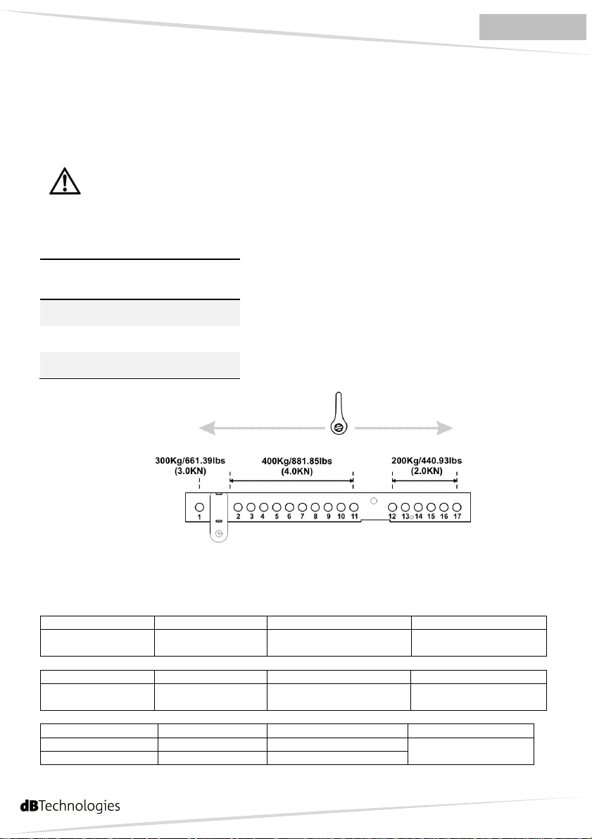
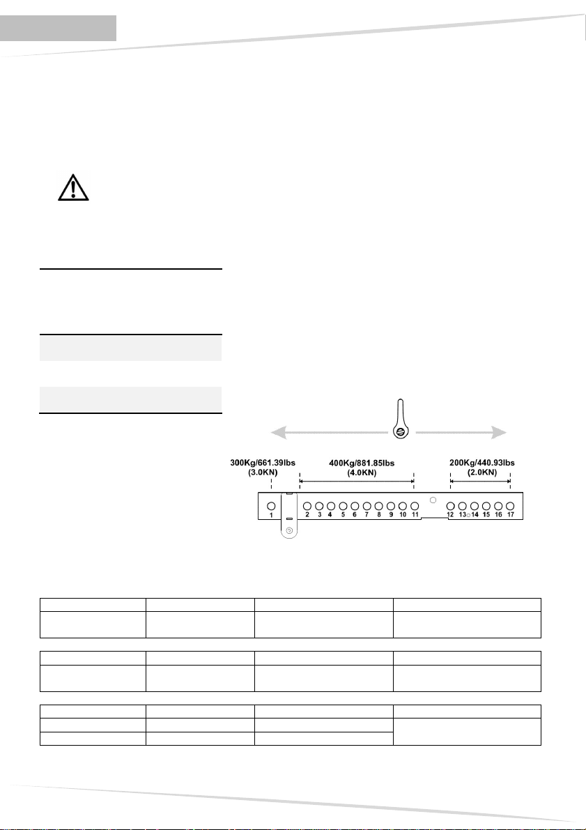
I calcoli strutturali attestano che il peso massimo applicabile al flybar DRK-M5 è in funzione del
punto di attacco del gancio di sollevamento.
Posizione
gancio di
Carico massimo
appendibile
sollevamento
1 300Kg/661.39lbs
(3,0KN)
2 – 11 400Kg /881.85lbs
(4,0KN)
12 – 17 200Kg/440,93lbs
(2,0KN)
GANGIO DI SOLLEVAMENTO
Configurazione
La modularità del sistema DVA MINI permette configurazioni sospese miste tra diffusori DVA
M2M/DVA M2S e DVA MS12. Per questo motivo è necessario calcolare il carico totale.
Esempio:
Quantità Peso per qtà Peso configurazione
DVA M2M/DVA M2S
2 + 2 (7,1x2)+(7,7x2)=29,6Kg 29,6Kg/65.26lbs
[0,29KN]
Quantità Peso per qtà Peso configurazione
DVA M2M/DVA M2S
4 + 4 (7,1x4)+(7,7x4)=59,2Kg 164,4Kg/362.44lbs
[1,61KN]
Quantità Peso per qtà Peso configurazione
DVA M2M/DVA M2S
DVA MS12
2 + 2 (7,1x2)+(7,7x2)=29,6Kg 82Kg/180.78lbs
2 (26,2x2)=52,4Kg
[0,80KN]
2
Page 4
ENGLISH
DVA MINI Digital Array System
The flybar device DRK-M5 and the related hanging systems provided for the speakers DVA M2M,
DVA M2S and DVA MS12 have been designed and verified by technical load tests according to the
documents: Italian Ministerial Decree of 14 January 2008 "New technical standards for
construction" and "Eurocode 1" and Eurocode 3" as regards the steel structures.
The system underwent technical tests and has been certificated in accordance with the values of
maximum load capacity declared by the Certificate of Conformity issued by CERMET.
DANGER! Carefully observe the allowable load according to the point of attachment of
the lifting hook. The non-respect of all the warnings may cause danger of falling of the
structure and its contents with potential damage to people, animals and property.
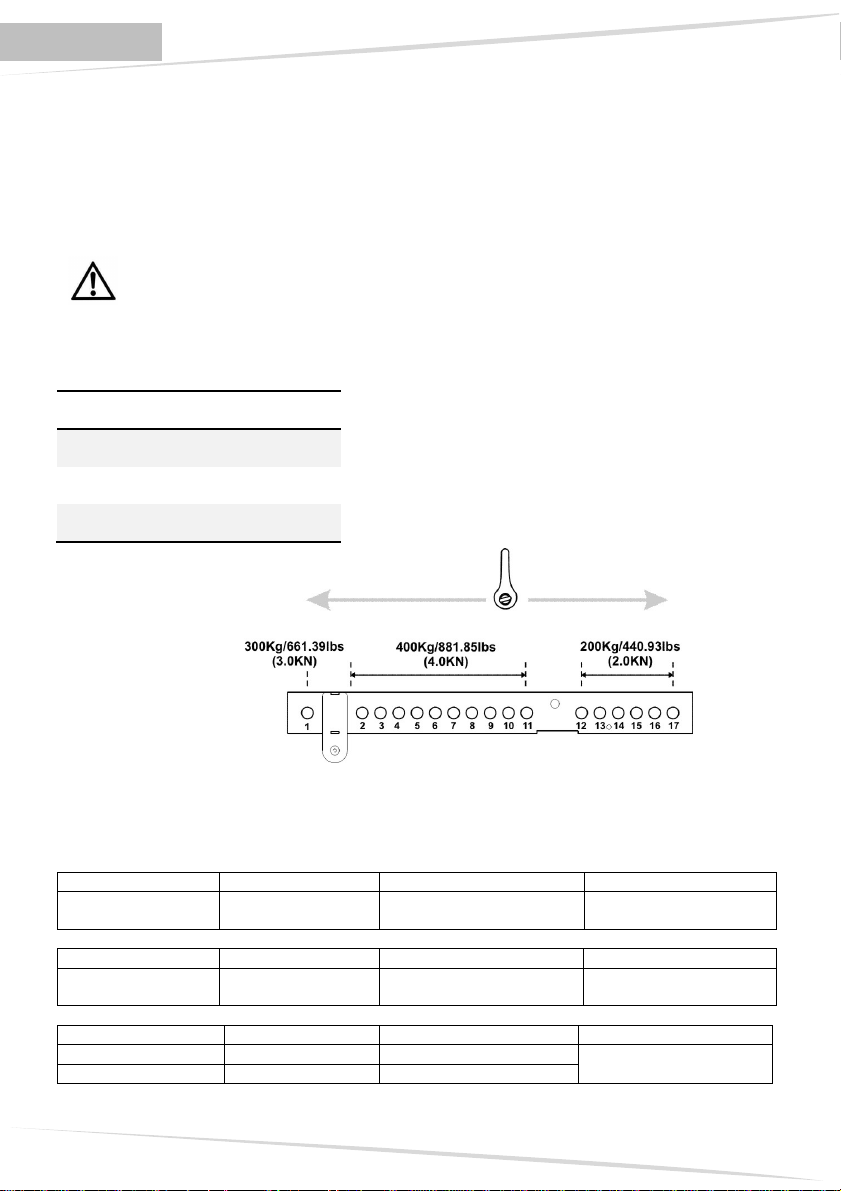
Structural calculations show that the maximum weight which can be applied to the flybar DRK-M5
depends on the point of attachment of the lifting hook.
Lifting hook
position
Maximun
load
1 300Kg/661.39lbs
(3,0KN)
2 – 11 400Kg /881.85lbs
(4,0KN)
12 – 17 200Kg/440,93lbs
(2,0KN)
LIFTING HOOK
Configuration
The modularity of the system DVA MINI allows mixed suspended configurations between speakers
DVA M2M/DVA M2S and DVA MS12. For this reason, it is necessary to calculate the total load.
Example:
Quantity Weight x qty Configuration weight
DVA M2M/DVA M2S
2 + 2 (7,1x2)+(7,7x2)=29,6Kg 29,6Kg/65.26lbs
[0,29KN]
Quantity Weight x qty Configuration weight
DVA M2M/DVA M2S
4 + 4 (7,1x4)+(7,7x4)=59,2Kg 164,4Kg/362.44lbs
[1,61KN]
Quantity Weight x qty Configuration weight
DVA M2M/DVA M2S
DVA MS12
2 + 2 (7,1x2)+(7,7x2)=29,6Kg 82Kg/180.78lbs
2 (26,2x2)=52,4Kg
[0,80KN]
3
Page 5

DEUTSCH
Die Vorrichtung flybar DRK-M5 und die entsprechenden Flugrahmensysteme für die Lautsprecher
DVA M2M, DVA M2S und DVA MS12, wurden entwickelt und mit technischen Bruchtests geprüft,
entsprechend der Vorgaben des Italienischen Ministerialdekrets D.M. vom 14.01.2008 “Neue
technische Richtlinien für den Bau” und, in Bezug auf die Stahlstrukturen, entsprechend “Eurocode
1” und "Eurocode 3”.
Das System wurde technisch geprüft und entsprechend der Werte der maximalen Tragkraft, die in
der Konformitätserklärung, die von CERMET ausgestellt wurde.
Die strukturellen Berechnungen bescheinigen, dass das maximal anwendbare Gewicht am flybar
DRK-M5 vom Anschlusspunkt des Hubhakens abhängt.
Position des
Anschlusspunktes
des Hubhakens
Konfiguration
Die Modularität des Systems DVA MINI erlaubt gemischte Hänge-Konfigurationen zwischen DVA
M2M/DVA M2S und DVA MS12. Daher muss immer die Gesamtlast berechnet werden.
Beispiel:
Anzahl Gewicht x Anzahl Konfigurationen Gewicht
DVA M2M/DVA M2S
Anzahl Gewicht x Anzahl Konfigurationen Gewicht
DVA M2M/DVA M2S
Anzahl Gewicht x Anzahl Konfigurationen Gewicht
DVA M2M/DVA M2S
DVA MS12
GEFAHR! Die zulässige Last in Bezug auf den Anschlusspunkt des Hubhakens muss
genau beachtet werden. Werden diese Warnhinweise nicht beachtet, kann die Struktur
und ihr Inhalt herunterfallen, was Schäden an Personen, Tieren und Gegenständen
verursachen kann.
Zulässigeload
Tragkraft
1 300Kg/661.39lbs
(3,0KN)
2 – 11 400Kg /881.85lbs
(4,0KN)
12 – 17 200Kg/440,93lbs
(2,0KN)
2 + 2 (7,1x2)+(7,7x2)=29,6Kg 29,6Kg/65.26lbs
4 + 4 (7,1x4)+(7,7x4)=59,2Kg 164,4Kg/362.44lbs
2 + 2 (7,1x2)+(7,7x2)=29,6Kg 82Kg/180.78lbs
2 (26,2x2)=52,4Kg
HUBHAKENS
[0,29KN]
[1,61KN]
[0,80KN]
4
Page 6
FRANÇAIS
DVA MINI Digital Array System
Le dispositif flybar DRK-M5 et les systèmes de suspension correspondants pour les haut-parleurs
DVA M2M, DVA M2S et DVA MS12 ont été conçus et vérifiés par le biais d'essais techniques de
rupture, conformément aux documents : Décret Ministériel Italien D.M du 14.01.2008 “Nouvelles
normes techniques pour les constructions” et “Eurocode 1” et “Eurocode 3” en ce qui concerne les
structures en acier.
Le système a été techniquement vérifié et certifié comme étant conforme aux valeurs de portée
maximum déclarées par le biais de l'Attestation de Conformité émise par CERMET.
DANGER ! Respecter scrupuleusement la charge admise en fonction du point de
fixation du crochet de soulèvement. L'absence de respect de toutes les instructions peut
provoquer un danger de chute de la structure et de son contenu, ce qui pourrait
occasionner des dommages à des personnes, des animaux et des choses.
Les calculs structuraux montrent que le poids maximum applicable au flybar DRK-M5 est fonction
du point de fixation du crochet de soulèvement.
Point de
fixation
du crochet
Capacité de
charge
admise
de
soulèvement
1 300Kg/661.39lbs
(3,0KN)
2 – 11 400Kg /881.85lbs
(4,0KN)
12 – 17 200Kg/440,93lbs
(2,0KN)
ROCHET DE SOULÈVEMENT
Configuration
La modularité du système DVA MINI permet des configurations suspendues mixtes entre
diffuseurs DVA M2M/DVA M2S e DVA MS12. C'est pourquoi il faut calculer la charge totale.
Exemple:
Quantité Poids par quantité Poids configuration
DVA M2M/DVA M2S
2 + 2 (7,1x2)+(7,7x2)=29,6Kg 29,6Kg/65.26lbs
[0,29KN]
Quantité Poids par quantité Poids configuration
DVA M2M/DVA M2S
4 + 4 (7,1x4)+(7,7x4)=59,2Kg 164,4Kg/362.44lbs
[1,61KN]
Quantité Poids par quantité Poids configuration
DVA M2M/DVA M2S
DVA MS12
2 + 2 (7,1x2)+(7,7x2)=29,6Kg 82Kg/180.78lbs
2 (26,2x2)=52,4Kg
[0,80KN]
5
Page 7

DVA Composer - Simulazione acustica di sistemi serie DVA
DVA Composer è un software di puntamento e simulazione acustica per tutti i modelli Line Array
della serie DVA e relativi Subwoofers.
Tale software permette di gestire un sistema stereo composto da line array e subwoofer,
simulandone separatamente la risposta acustica di entrambi
Vengono inoltre fornite all'utente una serie di informazioni quali: allineamento in fase tra i sistemi
sospesi e i relativi subwoofer a terra; vengono suggeriti gli angoli ottimali tra i moduli che
compongono i line array e i relativi preset di equalizzazione da assegnare, al fine di consentire
anche ad utenti non esperti di ottimizzare le performance del sistema.
Si raccomanda di scaricare gratuitamente il software DVA_Composer direttamente dal
sito dB Technologies (www.dbtechnologies.com) nella sezione dedicata «Software &
Controller»
DVA Composer Acoustical Simulation and aiming for DVA Systems
DVA Composer is a software for aiming and simulating acoustical response of all line arrays and
Subwoofers from DVA Series.
The software allows you to set up a stereo system composed by tops and subs, and simulates
separately the acoustical response of both
DVA Composer also gives to the user all the information about phase alignment between flown
systems and ground stacked subwoofers, as well as it suggests an optimized aiming of the line
arrays modules and their suggested EQ presets, in order to guarantee maximum performances
even for non-expert customers.
It is recommended to download DVA_Composer free software directly from dB
Technologies (www.dbtechnologies.com) in the special section «Software & Controller»
DVA Composer Simulation acoustique de systèmes de séries DVA
DVA Composer est un logiciel de direction et simulation acoustique pour tous les modèles de
lignes de source de la série DVA et les caissons de basse relatifs.
Ce logiciel permet de gérer un système stéréo composé de ligne source et de caissons de basse,
simulant séparément la réponse acoustique de chacun des deux
De plus, de nombreuses informations sont fournies à l'utilisateur, comme l'alignement en phase
entre les systèmes suspendus et les relatifs caissons de basse à terre, ou la syggestion d'angles
optimisés entre les modules de ligne de source et les préréglages d'égaliseur relatifs. Cela permet
d'optimiser les performances du système, même pour des utilisateurs non experts.
On conseille de télécharger gratuitement le logiciel DVA_Composer directement à partir
du site dB Technologies (www.dbtechnologies.com) dans la section dédiée « Software &
Controller »
DVA Composer Akustiksimulation für Systeme der Serie DVA
DVA Composer ist eine Software zur Beschallungsplanung und simulation für alle Line ArrayModelle der Serie DVA und den zugehörigen Subwoofern.
Sie ermöglicht die Verwaltung eines Stereosystems, das aus Line Arrays und Subwoofern besteht,
wobei das akustische Ansprechprofil jeweils separat simuliert wird.
Dem Nutzer werden eine Reihe von Daten geliefert, z.B. die Phasenanpassung zwischen den
Hängesystemen und den entsprechenden Subwoofern am Boden. Außerdem werden die
optimalen Winkel zwischen den Line Array-Modulen und den entsprechenden Equalizer-Presets
angegeben, so dass auch weniger erfahrene Benutzer die Leistungen des Systems optimieren
können.
Wir empfehlen, die Software DVA_Composer direkt von der Webseite dB Technologies
(www.dbtechnologies.com) im Abschnitt «software & Controller» herunterzuladen
6
Page 8

DVA MINI Digital Array System
c
----------------------------------------------------------------------------------------------------------------------------------
Kit completo
Complete kit
a
n°1 Telaio flybar
Flybar frame
c
d
n°1 Pin di bloccaggio
Fixing pin
n°1 Vite M5x30mm
Screw M5x30mm
b
n°2 Grillo con perno a vite
Screw pin anchor
e
n°1 Dado flangiato M5
Flange nut M5
----------------------------------------------------------------------------------------------------------------------------------
Fissaggio pin di bloccaggio al flybar
Fixing pin blocks to flybar
1
Identificare il foro di D5,5mm sulla staffa
Identify D5,5mm hole on the stirrup
e
a
2
Posizionare l’occhiello, posto alla fine del laccetto del pin di
bloccaggio, in corrispondenza del foro dedicato.
Fissare alla staffa l’occhiello tramite la vite M5x30mm e il
dado in dotazione.
Place the eyelet at the end of the fixing pin to dedicate hole.
d
Fix to stirrup the pin with M5x30mm and nut supplied.
3
Montaggio completato
Complete assembly
7
Page 9

INSTALLAZIONE CON ANGOLO DI COPERTURA POSITIVO
INSTALLATION WITH POSITIVE COVER ANGLE
Se si desidera ottenere un angolo di copertura positivo per particolari installazione, è necessario
utilizzate il foro di ancoraggio presente sulla parte anteriore della barra, in corrispondenza della
protezione in plastica frontale
A tale scopo è necessario rimuovere momentaneamente la protezione in plastica per il corretto
fissaggio dell’ancoraggio. A seguito sono riportate le istruzioni nel dettaglio.
If you would like to get a positive cover angle for particular installations, you have to use the anchor
hole on front part of the bar, near to frontal plastic protection
For this purpose, it is necessary to temporarily remove the plastic protection for the correct fitting of
the pin anchor. You can find some instructions in detail on follow.
1a
Svitare le 4 viti di fissaggio posteriori
Unscrew the 4 screws on the rear part
2a
Togliere le viti e sfilare il frontale in plastica
Remove the screw and unstring the plastic frontal
3a
Inserire e fissare il grillo con il perno a vite nel foro sulla parte
frontale
Insert and fixing the screw pin anchor on the hole on the frontal
part
4a
Riposizionare il frontale in plastica sul frontale del
telaio e avvitare le viti precedentemente tolte.
Replace the front plastic on the front of the chassis
and tighten the screws previously removed.
5a
Montaggio completato
Complete assembly
8
Page 10

DVA MINI Digital Array System
INSTALLAZIONE CON TRE PUNTI DI ANCORAGGIO
INSTALLATION WITH THREE FIXING POINTS
Se si desidera appendere il sistema con tre punti, è necessario utilizzate i fori di ancoraggio
presenti sulla parte anteriore della barra, in corrispondenza della protezione in plastica frontale
A tale scopo è necessario rimuovere momentaneamente la protezione in plastica per il corretto
fissaggio dell’ancoraggio.
If you would like to fix the system on three points, you have to use the anchor holes on front part of
the bar, near to frontal plastic protection. For this purpose, it is necessary to temporarily remove the
plastic protection for the correct fitting of the pins anchor.
1a
Svitare le 4 viti di fissaggio posteriori
Unscrew the 4 screws on the rear part
2a
Togliere le viti e sfilare il frontale in plastica
Remove the screw and unstring the plastic frontal
3a
Inserire e fissare il grillo con il perno a vite nel foro sulla parte
frontale
Insert and fixing the screw pin anchor on the hole on the frontal
part
5a
Montaggio completato
Complete assembly
Appendere SEMPRE il flybar utilizzando il perno con
grillo a vite in dotazione tramite i fori dedicati lungo la
barra.
Hanging ALWAYS the flybar with screw pin anchor
enclosed through the dedicate holes on the bar.
9
4a
Riposizionare il frontale in plastica sul frontale del telaio e
avvitare le viti precedentemente tolte.
Replace the front plastic on the front of the chassis and
tighten the screws previously removed.
Page 11

INSTALLAZIONE - INSTALLATION
INSTALLATIONEN - INSTALLATIONS
DRK M5 + DVA M2M/DVA M2S
10
Page 12

blocage des diffuseurs
DVA MINI Digital Array System
La leva Rossa deve essere posizionata come indicato in figura per garantire il
bloccaggio dei diffusori
The Red lever must be positioned as shown in the figure to ensure the locking of
the speakers
Der rote Hebel muss wie in Abbildung positioniert sein, um die Blockierung der
Lautsprecher zu garantieren
Le levier Rouge doit être positionné comme indiqué sur la figure pour garantir le
11
Page 13

Bloccare la staffa con il pin nel foro indicati in figura
Lock the bracket with the pin in hole indicated in the figure
Verriegeln Sie die Halterung mit dem Stift in Loch in den Figuren angedeutet
Verrouiller le support avec la broche dans le trou indiqué sur la figure
Appendere i diffusori utilizzando il perno con grillo a vite in dotazione, tramite i fori dedicati lungo la
barra.
Hanging the speaker boxes with screw pin anchor enclosed, using the dedicate holes on the bar.
12
Page 14

DRK M5 + DVA MS12
DVA MINI Digital Array System
13
Page 15

blocage des diffuseurs
La leva Rossa deve essere posizionata come indicato in figura per garantire il
bloccaggio dei diffusori
The Red lever must be positioned as shown in the figure to ensure the locking of
the speakers
Der rote Hebel muss wie in Abbildung positioniert sein, um die Blockierung der
Lautsprecher zu garantieren
Le levier Rouge doit être positionné comme indiqué sur la figure pour garantir le
14
Page 16

DVA MINI Digital Array System
Bloccare la staffa con il pin nel foro indicati in figura
Lock the bracket with the pin in hole indicated in the figure
Verriegeln Sie die Halterung mit dem Stift in Loch in den Figuren angedeutet
Verrouiller le support avec la broche dans le trou indiqué sur la figure
Appendere i diffusori utilizzando il perno con grillo a vite in dotazione, tramite i fori dedicati lungo la
barra.
Hanging the speaker boxes with screw pin anchor enclosed, using the dedicate holes on the bar.
15
Page 17

DRK M5 + DVA MS12 - DVA M2M/DVA M2S
Seguire le istruzioni riportate nel manuale d’uso dei diffusori per il corretto aggancio e blocco tra
diffusori.
Follow the instruction indicates on user manual of the speakers for the correct handling and fixing
between speakers.
Prima di procedere con il fissaggio dei diffusori DVA M2M sotto il subwoofer DVA MS12
è necessario posizionare i piedi in plastica di appoggio del subwoofer all’interno delle
sedi predisposte sotto il box.
Seguire le istruzioni a seguito.
Before to proceed with DVA M2M speaker fixing under the DVA MS12 subwoofer, it is
necessary to put the support plastic feet of the subwoofer inside the preset slots under
the box.
Follow the instruction below.
Ripetere la procedura per tutti e quattro i piedi.
Repeat the procedure for all four feet.
16
Page 18

DVA MINI Digital Array System
17
Page 19

18
Page 20

Cod. 420120212 Rev 1.0
A.E.B. Industriale Srl
Via Brodolini, 8
Località Crespellano
40053 VALSAMOGGIA
BOLOGNA (ITALIA)
Tel +39 051 969870
Fax +39 051 969725
www.dbtechnologies.com
info@dbtechnologies-aeb.com
 Loading...