

Page 1

MANUALE D’USO – Sezione 1
USER MANUAL - Section 1
BEDIENUNGSANLEITUNG - Abschnitt 1
CARACTERISTIQUES TECHNIQUES - Section 1
MANUAL DEL USUARIO - Sección 1
Le avvertenze nel presente manuale devono essere osservate congiuntamente al “MANUALE D’USO - Sezione2”.
The warnings in this manual must be observed together with the "User Manual - Section 2".
Die Warnungen in diesem Handbuch müssen in Verbindung mit der "BEDIENUNGSANLEITUNG - Abschnitt 2" beobachtet werden”.
Les avertissements speciés dans ce manuel doivent être respectés ainsi que les "CARACTERISTIQUES TECHNIQUES -Section 2".
Las advertencias del presente manual se deben tener en cuenta conjuntamente con las del “Manual del usuario” - Sección 2”.
Page 2

EMI CLASSIFICATION
According to the standards EN 55103 this equipment is designed and suitable to operate in E3 (or lower E2, E1)
Electromagnetic environments.
FCC CLASS B STATEMENT ACCORDING TO TITLE 47, CHAPTER I,
SUBCHAPTER A, PART 15, SUBPART B
This equipment has been tested and found to comply with the limits for a Class B digital device, pursuant to part
15 of the FCC Rules. These limits are designed to provide reasonable protection against harmful interference
in a residential installation. This equipment generates, uses and can radiate radio frequency energy and, if not
installed and used in accordance with the instructions, may cause harmful interference to radio communications.
However, there is no guarantee that interference will not occur in a particular installation. If this equipment does
cause harmful interference to radio or television reception, which can be determined by turning the equipment
off and on, the user is encouraged to try to correct the interference by one or more of the following measures:
—Reorient or relocate the receiving antenna.
—Increase the separation between the equipment and receiver.
—Connect the equipment into an outlet on a circuit different from that to which the receiver is connected.
—Consult the dealer or an experienced radio/TV technician for help.
Changes or modications not expressly approved by the party responsible for compliance could void the user’s
authority to operate the equipment.
WARNING
Make sure that the loudspeaker is securely installed in a stable position to avoid any injuries or damages to
persons or properties. For safety reasons di not place one loudspeaker on top of another without proper fastening
systems. Before hanging the loudspeaker check all the components for damages, deformations, missing or
damaged parts that may compromise safety during installation. If you use the loudspeakers outdoor avoid spots
exposed to bad weather conditions.
Contact dBTechnologies for accessories to be used with the speakers. dBTechnologies will not accept any
responsibility for damages caused by inappropiate accessories or additional devices.
SUB 915 - SUB918 Cod. 420120322 REV. 1.0
2
Page 3

ITALIANO
ENGLISH
DEUTSCH
FRANÇAIS
ESPAÑOL
SUB915 - SUB918 Cod. 420120322 REV. 1.0
3
Page 4

Italiano
INDICE
INDICE
1. INFORMAZIONI GENERALI ................................................................................................... 5
BENVENUTI! ........................................................................................................................ 5
PANORAMICA INTRODUTTIVA .......................................................................................... 5
RIFERIMENTI PER L’UTENTE ................................................................................................ 5
CARATTERISTICHE MECCANICHE ED ACUSTICHE ............................................................. 6
DIMENSIONI ............................................................................................................................................... 6
CARATTERISTICHE DELLA SEZIONE DI AMPLIFICAZIONE E DI CONTROLLO ................... 7
SEZIONE DI INPUT, OUTPUT E DI CONTROLLO ........................................................................................ 8
SEZIONE DI ALIMENTAZIONE .................................................................................................................... 9
2. PRIMA ACCENSIONE ............................................................................................................ 10
COLLEGAMENTO DEGLI INGRESSI E RILANCIO AUDIO .......................................................................... 11
COLLEGAMENTO DELL’ ALIMENTAZIONE ............................................................................................... 12
3. ESEMPI DI UTILIZZO ............................................................................................................. 13
UTILIZZO A TERRA ............................................................................................................ 13
UTILIZZO CON SPEAKER IN STACK ................................................................................... 13
UTILIZZO SU SUBWOOFER CON PALO TELESCOPICO..................................................... 13
4. RISOLUZIONE DEI PROBLEMI ............................................................................................. 14
5. SPECIFICHE TECNICHE ......................................................................................................... 15
GENERALE ................................................................................................................................................ 15
DATI ACUSTICI .......................................................................................................................................... 15
AMPLIFICATORE ....................................................................................................................................... 15
PROCESSORE ............................................................................................................................................ 16
INTERFACCIA UTENTE .............................................................................................................................. 16
INGRESSI E USCITE ................................................................................................................................... 16
SPECIFICHE DI ALIMENTAZIONE (ASSORBIMENTO / INSTALLAZIONE) ................................................. 16
DIMENSIONI ............................................................................................................................................. 17
SUB 915 - SUB918 Cod. 420120322 REV. 1.0
4
Page 5

Italiano
1. INFORMAZIONI GENERALI
BENVENUTI!
Grazie per aver acquistato un prodotto progettato e sviluppato in Italia da dBTechnologies! Questo subwoofer
attivo, versatile ed ergonomico, è frutto di una lunga esperienza nel campo della diffusione sonora, con l’impiego
di soluzioni ottimizzate in campo acustico ed elettronico, oltre che nella scelta dei materiali.
PANORAMICA INTRODUTTIVA
I nuovi subwoofer della serie SUB 900 sono equipaggiati rispettivamente con un woofer da 15” (SUB 915) ed un
woofer da 18” (SUB 918). La precisa progettazione ed ottimizzazione acustica consente prestazioni di alta qualità
in un prodotto dalle dimensioni contenute. L’elevata ergonomia e maneggevolezza dei cabinet li rendono facili
da trasportare.
Le caratteristiche principali di SUB 915 e SUB 918 sono:
• un progetto ergonomico, compatto e versatile, per contesti indoor e outdoor
• cabinet in legno per ottimizzare le prestazioni acustiche, con supercie esterna resistente per utilizzo
indoor e outdoor
• amplicatore digitale afdabile e silenzioso
• controlli del DSP dedicati, con selezione di Polarità, Delay, Xover, Sensitivity
RIFERIMENTI PER L’UTENTE
Per utilizzare al meglio il vostro subwoofer consigliamo di:
• leggere il manuale d’uso quick start presente nella confezione e questo manuale d’uso completo in
ogni sua parte e conservarlo per tutta la durata di vita del prodotto.
• registrare il prodotto sul sito http://www.dbtechnologies.com nella sezione “SUPPORTO”.
• conservare prova d’acquisto e GARANZIA (Manuale d’uso “sezione 2”).
SUB915 - SUB918 Cod. 420120322 REV. 1.0
5
Page 6

CARATTERISTICHE MECCANICHE ED ACUSTICHE
DIMENSIONI
Le dimensioni si SUB 915 e S918 sono:
• SUB 915: 620 x 457 x 620 (mm)
• SUB 918: 720 x 530 x 690 (mm)
Italiano
620
620 457
690 527
720
SUB 915 - SUB918 Cod. 420120322 REV. 1.0
6
Page 7
H
H
H
Italiano
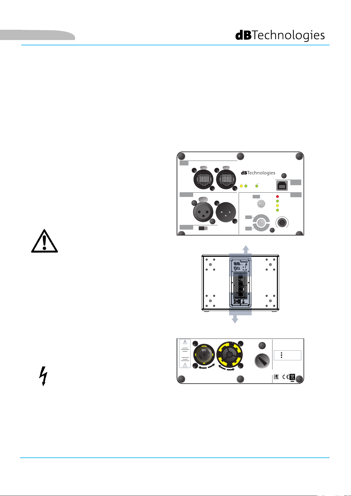
CARATTERISTICHE DELLA SEZIONE DI AMPLIFICAZIONE E DI CONTROLLO
L’amplicatore Digipro G3 è il cuore dei SUB 915 e SUB
918.
Il sistema è silenzioso ed il controllo è afdato ad un
DSP dedicato che gestisce diversi parametri.
La potenza di amplicazione sonora è di 900 W RMS.
RDNet
Il pannello dell’amplicatore è caratterizzato
da:
• Sezione di Input, Output e Controllo
• Sezione di Alimentazione
ATTENZIONE!
Balanced
Audio
Subwoofer
Polarity
Data
In
Normal Reversed
PPUUSSH
Input
PPUUSSH
Data
Out
Xover/Link
PPUUSSH
Output
DESIGNED & DEVELOPED
Link Active
Subwoofer
Delay
[ms]
Xover/Link [Hz]
Xover
MODE
Link
MODE
Service/
User
4,5
4,0
70
70
3,5
80
80
IN ITALY
Remote
Preset
Active
0
3,0
90
90
USB Data
Service
Main
Limiter
1,0
Signal
1,5
2,0
Status
2,5
ON
Input
100
110
110
100
Sens.
0dB
max
• Non tentare in nessun modo di
aprire l’amplicatore.
• In caso di surriscaldamento
eccessivo, il volume audio
viene ridotto gradualmente
no alla stabilizzazione termica
del modulo. Il livello viene
ristabilito automaticamente al
raggiungimento della corretta
temperatura di funzionamento.
• In caso di malfunzionamento,
interrompere immediatamente
l’alimentazione, scollegando il
modulo dalla rete, e contattare un
riparatore autorizzato.
ATTENZIONE!
• Non rimuovere mai la griglia
frontale di protezione del
prodotto. Per prevenire il pericolo
di scossa elettrica, in caso di
“CAUTION”
RISK OF
ELECTRICAL
SHOCK
DO NOT OPEN
“ATTENTION”
RISQUE DE
CHOCH
ELECTRIQUE
NE PAS OUVRIR
MAINS INPUT
220-240V~ 50-60Hz
2,7A
100-120V~ 50-60Hz
4,7A
MAINS LINKAUTO-RANGE
220-240V~ (13,3Amax)
3050Wmax
100-120V~ (15,3Amax)
1680Wmax
MAINS FUSE
220-240V~ (T4A L 250V~)
100-120V~ (T8A L 250V~)
(REPLACE FUSE WITH SAME RATINGS)
(REMPLACER LE FUSIBLE AVEC LE MÊME TYPE)
This device complies with part 15 of the
FCC Rules. Operation is subject to the
following two conditions: (1) This device
may not cause harmful interference, and
(2) this device must accept any interference
received, including interference that may
cause undesired operation.
SUB 915
SUB 918
Serial
Number
AEB INDUSTRIALE S.R.L.
Via Brodolini, 8
Località Crespellano
40053 VALSAMOGGIA (BO) - ITALY
danneggiamento accidentale
o sostituzione della griglia di
protezione (da effettuarsi presso il
servizio assistenza), disconnettere
immediatamente l’alimentazione.
Non connettere mai l’alimentazione
SEZIONE DI ALIMENTAZIONE SEZIONE DI INPUT, OUTPUT E CONTROLLO
di rete mentre la griglia è rimossa.
SUB915 - SUB918 Cod. 420120322 REV. 1.0
7
Page 8

H
H
H
SEZIONE DI INPUT, OUTPUT E DI CONTROLLO
Italiano
8
1
5
RDNet
Balanced
Audio
Subwoofer
Polarity
Data
In
PPUUSSH
Input
PPUUSSH
Normal Reversed
Data
Out
PPUUSSH
Output
Xover/Link
DESIGNED & DEVELOPED
Link Active
Subwoofer
Delay
[ms]
Xover/Link [Hz]
Xover
MODE
Link
MODE
Service/
User
4,5
4,0
3,5
80
70
70
80
2 4 7
IN ITALY
Remote
Preset
Active
0
3,0
90
90
USB Data
Service
max
Input
Sens.
0dB
Main
1,0
1,5
2,0
2,5
100
110
110
100
Limiter
Signal
Status
ON
9
6
3
1. INPUT
Connettore dell’ingresso, di tipo XLR (bilanciato). Per i dettagli di collegamento, vedi la sezione
COLLEGAMENTO DEGLI INGRESSI E RILANCIO AUDIO.
2. OUTPUT
Connettore dell’uscita, di tipo XLR (bilanciato). Selezionare la frequenza di taglio relativa alla modalità Xover/
Link nel relativo rotary. Per i dettagli di collegamento, vedi la sezione COLLEGAMENTO DEGLI INGRESSI E
RILANCIO AUDIO.
3. Input Sensitivity
Rotary di regolazione della sensibilità di ingresso.
4. Xover/Link rotary
Selettore che permette di impostare la frequenza di taglio a seconda della modalià prescelta (Link/Xover).
Agisce sul segnale rilanciato dai connettori Output Xover/Link
5. Selettore Subwoofer Polarity
Selettore che permette di intervenire sulla Polarità (Normal o Reverse)
6. LED (Limiter, Signal/ON)
Led di segnalazione. Il led Limiter si accende qualora intervenga il circuito di protezione interna, Signal/ON
rivela l’accensione del subwoofer e la presenza di segnale audio in ingresso.
SUB 915 - SUB918 Cod. 420120322 REV. 1.0
8
Page 9

Italiano
SEZIONE DI ALIMENTAZIONE
“CAUTION”
RISK OF
ELECTRICAL
SHOCK
DO NOT OPEN
“ATTENTION”
RISQUE DE
CHOCH
ELECTRIQUE
NE PAS OUVRIR
MAINS INPUT
220-240V~ 50-60Hz
2,7A
100-120V~ 50-60Hz
4,7A
10
MAINS LINKAUTO-RANGE
220-240V~ (13,3Amax)
3050Wmax
100-120V~ (15,3Amax)
1680Wmax
11
MAINS FUSE
220-240V~ (T4A L 250V~)
100-120V~ (T8A L 250V~)
(REPLACE FUSE WITH SAME RATINGS)
(REMPLACER LE FUSIBLE AVEC LE MÊME TYPE)
12
This device complies with part 15 of the
FCC Rules. Operation is subject to the
following two conditions: (1) This device
may not cause harmful interference, and
(2) this device must accept any interference
received, including interference that may
cause undesired operation.
SUB 915
SUB 918
Serial
Number
AEB INDUSTRIALE S.R.L.
Via Brodolini, 8
Località Crespellano
40053 VALSAMOGGIA (BO) - ITALY
7. Subwoofer Delay
Rotary che permette di impostare il ritardo (delay) in ms.
8. Sezione RDNet con LED di controllo
Sezione compatibile con cavi di rete dotati di connettori di tipo etherCON/RJ45.
In particolare “Data in” deve essere collegato a dispositivi come RDNet Control 2 o Control 8, “Data Out”
viene utilizzato per il rilancio della rete ad ulteriori moduli del line-array in congurazione daisy-chain.
I led relativi al funzionamento in rete (RDNet) del modulo assicurano un monitoraggio real-time.
In particolare, “Link” acceso segnala che la rete RDNet è attiva e ha riconosciuto il dispositivo, “Active” in
modalità lampeggiante che esiste trafco dati, “Remote Preset Active” che tutti i controlli locali sul pannello
amplicatore sono by-passati dal controllo remoto RDNet.
9. USB Data Service
Connettore USB per l’aggiornamento rmware.
10. MAINS INPUT
Compatibile con connettore powerCON TRUE1®.
11. MAINS LINK
Compatibile con connettore tipo powerCON TRUE1® per il rilancio dell’alimentazione ad altri moduli.
Per conoscere il numero massimo di moduli che si possono connettere in un sistema rilanciato, consultare la
sezione SPECIFICHE TECNICHE.
12. MAINS FUSE
Alloggio per il fusibile di rete
SUB915 - SUB918 Cod. 420120322 REV. 1.0
9
Page 10

2. PRIMA ACCENSIONE
La confezione del subwoofer SUB 915 / SUB 918 contiene:
• subwoofer 915 oppure subwoofer 918
• cavo di alimentazione POWERCON TRUE1
• quick start e documentazione cartacea relativa alla garanzia
CONFIGURAZIONE ED OTTIMIZZAZIONE
Italiano
Inserito e ruotato il connettore powerCON TRUE1®, connesso all’alimentazione
di rete, il subwoofer si accende.
Per ottimizzare l’utilizzo del subwoofer per alcune particolari congurazioni,
l’utente ha a disposizione sul pannello di controllo:
• Xover/Link [Hz]:
1. Link (il segnale presente alle uscite OUTPUTS è quello applicato al
woofer)
2. Xover (il segnale presente alle uscite OUTPUTS è ltrato con frequenza
di crossover di 120 Hz, per il rilancio a speaker, come ad esempio
B-HYPE e OPERA)
• Subwoofer Polarity:
1. Normal (Polarità normale del segnale audio)
2. Reverse (Polarità invertita, opzione utile per ottimizzare il fronte
d’onda invertendo la fase dell’onda acustica)
• Subwoofer Delay:
E’ possibile selezionare il delay applicabile per varie congurazioni,
secondo quanto riportato in serigraa.
Xover/Link [Hz]
Xover
MODE
Link
MODE
Subwoofer
Polarity
Subwoofer
Delay
[ms]
Output
Xover/Link
90
100
80
70
110
110
70
80
100
90
Normal Reversed
Service/
0
User
1,0
1,5
4,5
4,0
2,0
3,5
2,5
3,0
Input
Sens.
Prima dell’accensione, si consiglia di posizionare il selettore di livello Input
Sensitivity su 0 dB
0dB
max
SUB 915 - SUB918 Cod. 420120322 REV. 1.0
10
Page 11

Balanced
Audio
Input
Output
Xover/Link
PPUUSSHH
PPUUSSHH
PUSH
12
3
SPEAKER
SUBWOOFER
MIXER
H
H
H
H
MIXER
H
H
Italiano
COLLEGAMENTO DEGLI INGRESSI E RILANCIO AUDIO
Sono riportate 2 gure di esempio a
titolo puramente indicativo
In caso di collegamento tra
subwoofer e speaker:
1. Collegare l’uscita del mixer
al connettore di ingresso del
subwoofer
2. Collegare il connettore di uscita
del subwoofer all’ingresso dello
speaker.
3. Posizionare OUTPUT XOVER/LINK
[4] del subwoofer su XOVER, in
modo da rilanciare allo speaker
un segnale con frequenza di
crossover selezionabile col rotary
Xover/Link [Hz]
PPUUSSH
PUSH
SPEAKER
12
SUBWOOFER
Balanced
Audio
Input
PPUUSSH
PPUUSSH
PUSH
Output
Xover/Link
3
MIXER
MIXER
SPEAKER
12
3
PPUUSSH
PUSH
3
SPEAKER
12
Balanced
Audio
Input
PPUUSSH
Output
Xover/Link
MIXER
SUBWOOFER
Balanced
Audio
Input
PPUUSSH
Output
Xover/Link
SUBWOOFER
MIXER
MIXER
SUB915 - SUB918 Cod. 420120322 REV. 1.0
11
Page 12

Italiano
SUB 915 - SUB918 Cod. 420120322 REV. 1.0
12
Page 13

Italiano
3. ESEMPI DI UTILIZZO
• Non sono ammessi tipi di installazione diversi da quelli qui illustrati.
• In nessun caso utilizzare le maniglie del subwoofer per appenderlo
• Vericare sempre che il posizionamento sia stabile, e che l’installazione non costituisca fonte di
pericolo per persone, animali o cose.
UTILIZZO A TERRA
E’ possibile l’utilizzo dei subwoofer 915 e 918 direttamente a
terra.
UTILIZZO CON SPEAKER IN STACK
E’ possibile l’utilizzo di uno speaker montato direttamente sul
subwoofer 915 o 918 tramite il mini-palo di diametro 35 mm
DS2-S (es. serie: INGENIA, B-HYPE, OPERA).
E’ necessario un ssaggio addizionale
UTILIZZO SU SUBWOOFER CON PALO
TELESCOPICO
E’ possibile l’utilizzo di un solo speaker montato su palo
diametro 35 mm. L’accessorio di riferimento è DS-2 (palo
telescopico).
E’ necessario un ssaggio addizionale
SUB915 - SUB918 Cod. 420120322 REV. 1.0
13
Page 14

4. RISOLUZIONE DEI PROBLEMI
Il subwoofer non si accende:
1. Vericare la corretta presenza dell’alimentazione a monte dell’impianto.
2. Vericare che il cavo di alimentazione sia correttamente inserito.
Il subwoofer si accende ma non emette nessun suono:
1. Vericare che il collegamento in ingresso del segnale audio sia correttamente effettuato.
2. Vericare che i cavi utilizzati non siano danneggiati.
3. Vericare che il mixer o la sorgente audio sia accesa e mostri chiaramente la presenza di segnale in
uscita.
4. Vericare il livello generale tramite il controllo “Input Sensitivity”.
Italiano
Il diffusore emette un suono non adeguato:
1. Vericare che i cavi utilizzati non siano danneggiati, nel qual caso sostituirli (un cavo danneggiato può
portare a perdita o alterazione del segnale).
2. Vericare che le impostazioni sul pannello di controllo siano impostate correttamente.
SUB 915 - SUB918 Cod. 420120322 REV. 1.0
14
Page 15

Italiano
5. SPECIFICHE TECNICHE
GENERALE
Tipologia:
DATI ACUSTICI
Risposta in frequenza [-10dB]:
Max SPL (1m):
LF:
LF voice coil:
Frequenza di crossover:
AMPLIFICATORE
Subwoofer attivo
45 - Cut freq Hz (SUB 915) / 42 -Cut Freq Hz (SUB 918)
133 dB (SUB 915) / 134 dB (SUB 918)
15” (SUB 915) / 18” (SUB 918)
4”
Variabile (70 Hz - 80 Hz - 90 Hz - 100 Hz - 110 Hz)
Tipologia:
Classe di amplicazione
Alimentazione
Potenza di amplicazione RMS:
SUB915 - SUB918 Cod. 420120322 REV. 1.0
DIGIPRO G3
Classe D
PowerCON TRUE1
900 W
15
Page 16

PROCESSORE
Italiano
Controller interno:
Limiter:
DSP 28/56 bit
Peak, RMS, Termico
INTERFACCIA UTENTE
Controlli:
Delay, Xover/Link, Polarity, Sensitivity
INGRESSI E USCITE
Ingressi:
Uscite:
2 x XLR Balanced Inputs
2x XLR Balanced Outputs
SPECIFICHE DI ALIMENTAZIONE (ASSORBIMENTO / INSTALLAZIONE)
Assorbimento a 1/8 della potenza in
condizioni medie di utilizzo (*):
1,2 A (220-240V~) - 2 A (110-120V~)
Assorbimento a 1/3 della potenza in
condizioni massime di utilizzo (**):
Assorbimento con speaker acceso in
assenza di segnale (idle):
Corrente di inrush:
* NOTA PER L’INSTALLATORE: Valori riferiti a 1/8 della potenza, in condizioni medie di funzionamento (programma musicale con clipping raro
o assente). Si consiglia per qualsiasi tipo di congurazione di considerarli i valori minimi di dimensionamento.
** NOTA PER L’INSTALLATORE: Valori riferiti a 1/3 della potenza, in condizioni pesanti di funzionamento (programma musicale con frequente
clipping e intervento del limiter). E’ consigliabile il dimensionamento secondo questi valori in caso di installazioni e tour professionali.
SUB 915 - SUB918 Cod. 420120322 REV. 1.0
2.7 A (220-240V~) - 4.7 A (110-120V~)
21 W
21.04 A
16
Page 17

Italiano
DIMENSIONI
Materiale:
Griglia:
Maniglie:
Montaggio su palo:
Larghezza:
Altezza:
Profondità:
Peso:
Legno multistrato (con vernice protettiva nera)
Lavorazione CNC
2, laterali
Sì, 36 mm (predisposizione: M20)
620 mm (SUB 915) 720 mm (SUB 918)
457 mm (SUB 915) 530 mm (SUB 918)
620 mm (SUB 915) 690 mm (SUB 918)
34.8 kg (SUB 915) 41.8 kg (SUB 918)
Caratteristiche, speciche e aspetto dei prodotti sono soggetti a possibili cambiamenti senza previa
comunicazione. dBTechnologies si riserva il diritto di apportare cambiamenti o miglioramenti nel design o nelle
lavorazioni senza assumersi l’obbligo di cambiare o migliorare anche i prodotti precedentemente realizzati.
A.E.B. Industriale Srl
Via Brodolini, 8
Località Crespellano
40053 VALSAMOGGIA
BOLOGNA (ITALIA)
Tel +39 051 969870
Fax +39 051 969725
www.dbtechnologies.com
info@dbtechnologies-aeb.com
SUB915 - SUB918 Cod. 420120322 REV. 1.0
17
Page 18

English
TABLE OF CONTENTS
TABLE OF CONTENTS
1. GENERAL INFORMATION .................................................................................................... 19
WELCOME! ....................................................................................................................... 19
PRODUCT OVERVIEW ....................................................................................................... 19
USER REFERENCE .............................................................................................................. 19
MECHANICAL AND ACOUSTICAL FEATURES ................................................................... 20
DIMENSIONS ............................................................................................................................................ 20
FEATURES OF THE AMPLIFIER AND CONTROL SECTIONS .............................................. 21
INPUT, OUTPUT AND CONTROL SECTION .............................................................................................. 22
POWER SUPPLY UNIT SECTION ............................................................................................................... 23
2. FIRST POWER-UP .................................................................................................................. 24
INPUT CONNECTIONS AND AUDIO DAISY CHAIN ................................................................................. 25
3. USAGE EXAMPLES ................................................................................................................ 27
FLOOR USAGE ................................................................................................................... 27
USAGE WITH SPEAKER IN A STACK ................................................................................. 27
USAGE ON SUBWOOFER WITH TELESCOPIC POLE ......................................................... 27
4. TROUBLESHOOTING ............................................................................................................ 28
5. SPECIFICATIONS ................................................................................................................... 29
GENERAL INFORMATION ........................................................................................................................ 29
ACOUSTICAL SPECIFICATIONS ................................................................................................................. 29
AMPLIFIER ................................................................................................................................................ 29
PROCESSOR .............................................................................................................................................. 30
USER INTERFACE ...................................................................................................................................... 30
INPUTS & OUTPUTS ................................................................................................................................. 30
POWER SUPPLY SPECIFICATIONS (ABSORPTION / INSTALLATION) ....................................................... 30
DIMENSIONS ............................................................................................................................................ 31
SUB 915 - SUB918 Code 420120322 REV. 1.0
18
Page 19

English
1. GENERAL INFORMATION
WELCOME!
Thanks for purchasing a product designed and developed in Italy by dBTechnologies! This ergonomic and versatile
active subwoofer is the result of a long experience in the sound reinforcement industry, making use of optimized
sound, electronic and material research solutions.
PRODUCT OVERVIEW
The new SUB 900 subwoofers are equipped with a 15” woofer (SUB 915) and an 18” woofer (SUB 918),
respectively. Accurate design and sound optimisation allow for high-quality performance in a compact product.
Cabinets high ergonomics and ease of handling make them easy to transport.
SUB 915 and SUB 918 main features are:
• an ergonomic, compact and versatile project, for both indoors and outdoors
• wooden cabinets for acoustic performance optimisation, with resistant external surfaces for both
indoor and outdoor use
• reliable, silent digital amplier
• dedicated DSP controls, with Polarity, Delay, Xover, Sensitivity selection
USER REFERENCE
To make the most of your subwoofer, we recommend that you:
• read the quick start user manual included in the package and this user manual thoroughly and keep
this manual during the whole life of the product.
• Register your product at http://www.dbtechnologies.com under “SUPPORT”.
• keep proof of purchase and WARRANTY (User manual “section 2”).
SUB915 - SUB918 Code 420120322 REV. 1.0
19
Page 20

MECHANICAL AND ACOUSTICAL FEATURES
DIMENSIONS
SUB 915 and S918 have the following sizes:
• SUB 915: 620 x 457 x 620 (mm)
• SUB 918: 720 x 530 x 690 (mm)
English
620
620 457
690 527
720
SUB 915 - SUB918 Code 420120322 REV. 1.0
20
Page 21

H
H
H
English
FEATURES OF THE AMPLIFIER AND CONTROL SECTIONS
The Digipro G3 amplier is at the heart of SUB 915 and
SUB 918.
The system is silent and is controlled by a dedicated
DSP that manages the different parameters.
The sound amplication power is 900 W RMS.
RDNet
The amplier panel is made up of:
• Input, Output and Control Section
• Power Supply Unit Section
WARNING!
Balanced
Audio
Subwoofer
Polarity
Data
In
Normal Reversed
PPUUSSH
Input
PPUUSSH
Data
Out
Xover/Link
PPUUSSH
Output
DESIGNED & DEVELOPED
Link Active
Subwoofer
Delay
[ms]
Xover/Link [Hz]
Xover
MODE
Link
MODE
Service/
User
4,5
4,0
70
70
3,5
80
80
IN ITALY
Remote
Preset
Active
0
1,0
3,0
90
90
USB Data
Service
Main
Limiter
Signal
1,5
2,0
Status
2,5
ON
Input
100
110
110
100
Sens.
0dB
max
• Never attempt to disassemble the
amplier in any way.
• If the module heats up excessively,
the audio volume is gradually
reduced until the module is
thermally stabilized. The audio is
automatically restored when the
normal operating temperature is
reached.
• In the event of a malfunction,
remove power supply immediately
by disconnecting the unit from
the power mains and contact an
authorised repair centre.
WARNING!
• Never remove the front grille
protecting the product. To prevent
the danger of electric shock, in
case of accidental damage or
“CAUTION”
RISK OF
ELECTRICAL
SHOCK
DO NOT OPEN
“ATTENTION”
RISQUE DE
CHOCH
ELECTRIQUE
NE PAS OUVRIR
MAINS INPUT
220-240V~ 50-60Hz
2,7A
100-120V~ 50-60Hz
4,7A
MAINS LINKAUTO-RANGE
220-240V~ (13,3Amax)
3050Wmax
100-120V~ (15,3Amax)
1680Wmax
MAINS FUSE
220-240V~ (T4A L 250V~)
100-120V~ (T8A L 250V~)
(REPLACE FUSE WITH SAME RATINGS)
(REMPLACER LE FUSIBLE AVEC LE MÊME TYPE)
This device complies with part 15 of the
FCC Rules. Operation is subject to the
following two conditions: (1) This device
may not cause harmful interference, and
(2) this device must accept any interference
received, including interference that may
cause undesired operation.
SUB 915
SUB 918
Serial
Number
AEB INDUSTRIALE S.R.L.
Via Brodolini, 8
Località Crespellano
40053 VALSAMOGGIA (BO) - ITALY
replacement of the protection
grille (to be carried out at the
service), immediately disconnect
the power supply. Never connect
mains power supply when the
grille is removed.
POWER SUPPLY UNIT SECTION INPUT, OUTPUT AND CONTROL SECTION
SUB915 - SUB918 Code 420120322 REV. 1.0
21
Page 22

H
H
H
INPUT, OUTPUT AND CONTROL SECTION
English
8
1
5
RDNet
Balanced
Audio
Subwoofer
Polarity
Data
In
PPUUSSH
Input
PPUUSSH
Normal Reversed
Data
Out
PPUUSSH
Output
Xover/Link
DESIGNED & DEVELOPED
Link Active
Subwoofer
Delay
[ms]
Xover/Link [Hz]
Xover
MODE
Link
MODE
Service/
User
4,5
4,0
3,5
80
70
70
80
2 4 7
IN ITALY
Remote
Preset
Active
0
3,0
90
90
USB Data
Service
max
Input
Sens.
0dB
Main
1,0
1,5
2,0
2,5
100
110
110
100
Limiter
Signal
Status
ON
9
6
3
1. INPUT
XLR (balanced) input connector. For further details concerning connection, refer to INPUT CONNECTIONS AND
AUDIO DAISY CHAIN.
2. OUTPUT
XLR (balanced) output connector. Select the cut-off frequency based on the Xover/Link mode using the
relevant rotary control. For further details concerning connection, refer to INPUT CONNECTIONS AND AUDIO
DAISY CHAIN.
3. Input Sensitivity
Rotary control to adjust the input sensitivity.
4. Xover/Link rotary
Selector that allows setting the cut-off frequency based on the selected mode (Link/Xover). It acts on the
daisy-chained signal from Xover/Link Output connectors.
5. Subwoofer Polarity selector
Selector that allows adjusting the Polarity (Normal or Reverse)
6. LED (Limiter, Signal/ON)
Indicator LEDs. The Limiter LED turns on when the internal protection circuit is triggered, while Signal/ON
indicates subwoofer power-up as well as the presence of an input audio signal.
SUB 915 - SUB918 Code 420120322 REV. 1.0
22
Page 23

English
POWER SUPPLY UNIT SECTION
“CAUTION”
RISK OF
ELECTRICAL
SHOCK
DO NOT OPEN
“ATTENTION”
RISQUE DE
CHOCH
ELECTRIQUE
NE PAS OUVRIR
MAINS INPUT
220-240V~ 50-60Hz
2,7A
100-120V~ 50-60Hz
4,7A
10
MAINS LINKAUTO-RANGE
220-240V~ (13,3Amax)
3050Wmax
100-120V~ (15,3Amax)
1680Wmax
11
MAINS FUSE
220-240V~ (T4A L 250V~)
100-120V~ (T8A L 250V~)
(REPLACE FUSE WITH SAME RATINGS)
(REMPLACER LE FUSIBLE AVEC LE MÊME TYPE)
12
This device complies with part 15 of the
FCC Rules. Operation is subject to the
following two conditions: (1) This device
may not cause harmful interference, and
(2) this device must accept any interference
received, including interference that may
cause undesired operation.
SUB 915
SUB 918
Serial
Number
AEB INDUSTRIALE S.R.L.
Via Brodolini, 8
Località Crespellano
40053 VALSAMOGGIA (BO) - ITALY
7. Subwoofer Delay
Rotary control that allows setting the delay in ms.
8. RDNet section with control LEDs
Section compatible with network cables with etherCON/RJ45 connectors.
In particular, "Data in" must be connected to devices such as RDNet Control 2 or Control 8; "Data Out" is
used to link the network to additional modules of the line array in daisy-chain conguration.
The LEDs relating to module network operation (RDNet) ensure real-time monitoring.
In particular, if "Link" is on the RDNet network is active and has acknowledged the device, if "Active" is
ashing there is data trafc, if "Remote Preset Active" is on all local control on the amplier panel are by-
passed by the RDNet remote control.
9. Service Data USB
USB connector for rmware update.
10. MAINS INPUT
Compatible with powerCON TRUE1® connector.
11. MAINS LINK
Compatible with powerCON TRUE1® connector for power daisy chain to other modules.
To nd the maximum number of modules that can be connected in a re-linked system, see the TECHNICAL
SPECIFICATIONS section.
12. MAINS FUSE
Housing for the mains fuse
SUB915 - SUB918 Code 420120322 REV. 1.0
23
Page 24

2. FIRST POWER-UP
The package of SUB 915 / SUB 918 subwoofer contains:
• 915 or 918 subwoofer
• POWERCON TRUE1 power cable
• quick start user manual and warranty documents in hard copy
CONFIGURATION AND OPTIMISATION
English
The subwoofer will turn on after inserting, turning and connecting the
powerCON TRUE1® connector to the power supply.
For subwoofer use optimisation in given congurations, the control panel
displays the following:
• Xover/Link [Hz]:
1. Link (the signal present at OUTPUTS is the one applied to the woofer)
2. Xover (the signal present at OUTPUTS is ltered with a crossover
frequency of 120 Hz, for daisy chain to a speaker, such as B-HYPE and
OPERA)
• Subwoofer Polarity:
1. Normal (audio signal normal polarity)
2. Reverse (reverse polarity, useful for wavefront optimisation through
acoustic wave phase reversal)
• Subwoofer Delay:
It is possible to select the applicable delay for various congurations,
according to what is stated on the silk-screen print.
Xover/Link [Hz]
Xover
MODE
Link
MODE
Subwoofer
Polarity
Subwoofer
Delay
[ms]
Output
Xover/Link
90
100
80
70
110
110
70
80
100
90
Normal Reversed
Service/
0
User
1,0
1,5
4,5
4,0
2,0
3,5
2,5
3,0
Input
Sens.
Before power-up, set Input Sensitivity level selector to 0 dB
0dB
max
SUB 915 - SUB918 Code 420120322 REV. 1.0
24
Page 25

Balanced
Audio
Input
Output
Xover/Link
PPUUSSHH
PPUUSSHH
PUSH
12
3
SPEAKER
SUBWOOFER
MIXER
H
H
H
H
MIXER
H
H
English
INPUT CONNECTIONS AND AUDIO DAISY CHAIN
Two example gures are shown for
illustrative purposes only.
In the event of a connection between
subwoofer and speaker:
1. Connect mixer output to
subwoofer input connector
2. Connect subwoofer output
connector to speaker input.
3. Set subwoofer OUTPUT XOVER/
LINK [4] to XOVER, in order
to daisy-chain a signal to the
speaker having a crossover
frequency that can be selected
with the Xover/Link rotary
control [Hz]
PPUUSSH
PUSH
SPEAKER
12
SUBWOOFER
Balanced
Audio
Input
PPUUSSH
PPUUSSH
PUSH
Output
Xover/Link
3
MIXER
MIXER
SPEAKER
12
3
PPUUSSH
PUSH
3
SPEAKER
12
Balanced
Audio
Input
PPUUSSH
Output
Xover/Link
MIXER
SUBWOOFER
Balanced
Audio
Input
PPUUSSH
Output
Xover/Link
SUBWOOFER
MIXER
MIXER
SUB915 - SUB918 Code 420120322 REV. 1.0
25
Page 26

English
SUB 915 - SUB918 Code 420120322 REV. 1.0
26
Page 27

English
3. USAGE EXAMPLES
• Types of installation other than those here described are not allowed.
• Never use the handles to suspend the subwoofer
• Always check that the positioning is stable and that the installation does not pose a danger to
people, animals or property.
FLOOR USAGE
915 and 918 subwoofers may be used directly on the oor.
USAGE WITH SPEAKER IN A STACK
A speaker may be installed directly on 915 or 918 subwoofer
by means of a DS2-S 35 mm diameter mini-pole (e.g. series:
INGENIA, B-HYPE, OPERA).
An additional fastener is required.
USAGE ON SUBWOOFER WITH TELESCOPIC
POLE
It is possible to use only one speaker mounted on a 35 mm
diameter pole. The reference accessory is DS-2 (telescopic pole).
An additional fastener is required.
SUB915 - SUB918 Code 420120322 REV. 1.0
27
Page 28

4. TROUBLESHOOTING
The subwoofer will not turn on:
1. Check that power supply is present upstream of the installation.
2. Ensure that the power supply cable is properly plugged in.
The subwoofer turns on but produces no sound:
1. Check that the input connection of the audio signal is correctly performed.
2. Check the cables for damage.
3. Ensure that the mixer or audio source is on and an output signal is present.
4. Check the general level through the "Input Sensitivity" control.
English
Loudspeaker sound is inappropriate:
1. Check the cables for damage and replace them as required (a damaged cable may lead to signal loss or
alteration).
2. Check that the settings on the control panel are correctly set.
SUB 915 - SUB918 Code 420120322 REV. 1.0
28
Page 29

English
5. SPECIFICATIONS
GENERAL INFORMATION
Type:
ACOUSTICAL SPECIFICATIONS
Frequency response [-10dB]:
Max SPL (1m):
LF:
LF voice coil:
Crossover frequency:
AMPLIFIER
Active subwoofer
45 - Cut freq Hz (SUB 915) / 42 -Cut Freq Hz (SUB 918)
133 dB (SUB 915) / 134 dB (SUB 918)
15” (SUB 915) / 18” (SUB 918)
4”
Variable (70 Hz - 80 Hz - 90 Hz - 100 Hz - 110 Hz)
Type:
Amplication class
Power supply
RMS amplier power:
SUB915 - SUB918 Code 420120322 REV. 1.0
DIGIPRO G3
Class D
PowerCON TRUE1
900 W
29
Page 30

PROCESSOR
English
Internal controller:
Limiter:
28-bit/56-bit DSP
Peak, RMS, Thermal
USER INTERFACE
Controls:
Delay, Xover/Link, Polarity, Sensitivity
INPUTS & OUTPUTS
Inputs:
Outputs:
2 x XLR Balanced Inputs
2x XLR Balanced Outputs
POWER SUPPLY SPECIFICATIONS (ABSORPTION / INSTALLATION)
Absorption at 1/8th of power in
medium use conditions (*):
1.2 A (220-240V~) - 2 A (110-120V~)
Absorption at 1/3rd of power in
maximum use conditions (**):
Absorption with speaker on in
no-signal condition (idle):
Inrush current:
* NOTE FOR INSTALLER: Values refer to 1/8th of power, under average operating conditions (music programme with occasional or no
clipping). For any type of conguration we recommend to consider them as minimum sizing values.
** NOTE FOR INSTALLER: Values refer to 1/3rd of power, under heavy operating conditions (music programme with frequent clipping and
limiter activation). In case of professional installations and tours we recommend sizing according to these values.
SUB 915 - SUB918 Code 420120322 REV. 1.0
2.7 A (220-240V~) - 4.7 A (110-120V~)
21 W
21.04 A
30
Page 31

English
DIMENSIONS
Material:
Grille:
Handles:
Pole mount:
Width:
Height:
Depth:
Weight:
Plywood (with protective black paint)
NC-machined
2, on sides
Yes, 36 mm (provision: M20)
620 mm (SUB 915) 720 mm (SUB 918)
457 mm (SUB 915) 530 mm (SUB 918)
620 mm (SUB 915) 690 mm (SUB 918)
34.8 kg (SUB 915) 41.8 kg (SUB 918)
Product features, specications and appearance are subject to changes without prior notice. dBTechnologies
reserves the right to make changes or improvements in design or manufacture without any obligation to
incorporate such changes or improvements in products manufactured before their introduction.
A.E.B. Industriale Srl
Via Brodolini, 8
Località Crespellano
40053 VALSAMOGGIA
BOLOGNA (ITALY)
Tel +39 051 969870
Fax +39 051 969725
www.dbtechnologies.com
info@dbtechnologies-aeb.com
SUB915 - SUB918 Code 420120322 REV. 1.0
31
Page 32

Deutsch
INHALTSVERZEICHNIS
INHALTSVERZEICHNIS
1. ALLGEMEINE INFORMATIONEN ......................................................................................... 33
WILLKOMMEN! ................................................................................................................ 33
EINLEITENDER ÜBERBLICK ............................................................................................... 33
ANHALTSPUNKTE FÜR DEN BENUTZER ........................................................................... 33
MECHANISCHE UND AKUSTISCHE EIGENSCHAFTEN ...................................................... 34
ABMESSUNGEN ........................................................................................................................................ 34
EIGENSCHAFTEN DES VERSTÄRKUNGS- UND STEUERBEREICHS .................................... 35
INPUT-, OUTPUT- UND STEUERBEREICH ................................................................................................. 36
VERSORGUNGSBEREICH .......................................................................................................................... 37
2. ERSTMALIGES EINSCHALTEN .............................................................................................. 38
VERBINDUNG DER AUDIO-EINGÄNGE UND RÜCKLAUF ....................................................................... 39
3. ANWENDUNGSBEISPIELE ................................................................................................... 41
VERWENDUNG AM BODEN ............................................................................................. 41
VERWENDUNG MIT LAUTSPRECHER IM STACK .............................................................. 41
VERWENDUNG AUF EINEM SUBWOOFER MIT TELESKOPPFOSTEN ............................. 41
4. PROBLEMABHILFE ............................................................................................................... 42
5. TECHNISCHE DATEN ............................................................................................................ 43
ALLGEMEINE ANGABEN .......................................................................................................................... 43
AKUSTIK-DATEN ....................................................................................................................................... 43
VERSTÄRKER ............................................................................................................................................ 43
PROZESSOR .............................................................................................................................................. 44
BENUTZEROBERFLÄCHE .......................................................................................................................... 44
EINGÄNGE UND AUSGÄNGE ................................................................................................................... 44
VERSORGUNGSSPEZIFIKATIONEN (AUFNAHME / INSTALLATION) ........................................................ 44
ABMESSUNGEN ........................................................................................................................................ 45
SUB 915 - SUB918 Art.-Nr. 420120322 REV. 1.0
32
Page 33

Deutsch
1. ALLGEMEINE INFORMATIONEN
WILLKOMMEN!
Wir danken Ihnen, dass Sie sich für den Kauf eines von dBTechnologies in Italien entworfenen und entwickelten
Produkts entschieden haben! Dieser vielseitige und ergonomische Aktiv-Subwoofer ist das Resultat einer
langjährigen Erfahrung im Bereich der Beschallungssysteme mit optimierten Lösungen in Sachen Akustik und
Elektronik sowie in der Wahl der Materialien.
EINLEITENDER ÜBERBLICK
Die neuen Subwoofer der Serie SUB 900 sind jeweils mit einem 15-Zoll-Tieftöner (SUB 915) und einem 18-ZollTieftöner (SUB 918) ausgestattet. Die präzise Planung und die akustische Optimierung bieten eine hochqualitative
Leistung in einem Produkt im kompakten Format. Dank ihres hohen ergonomischen Aspekts und ihrer
Handlichkeit lassen sich die Gehäuse leicht transportieren.
Die Haupteigenschaften von SUB 915 und SUB 918 sind:
• ein ergonomisches, kompaktes und vielseitiges Design für Indoor- und Outdoor-Kontexte
• Holzgehäuse zur Optimierung der akustischen Leistung mit widerstandsfähiger Außenäche für den
Indoor- und Outdoor-Einsatz
• zuverlässiger Verstärker mit besonderer Laufruhe
• spezische Steuerungen des DSP mit Wahlmöglichkeit der Polarität, von Delay, Xover, Sensitivity
ANHALTSPUNKTE FÜR DEN BENUTZER
Zur besten Verwendung Ihres Subwoofers empfehlen wir:
• die in der Packung enthaltene Quick Start-Anleitung sowie die vorliegende komplette
Bedienungsanleitung in allen ihren Teilen zu lesen und sie über die gesamte Lebensdauer des Produkts
hinweg aufzubewahren;
• das Produkt auf der Website http://www.dbtechnologies.com im Abschnitt „ASSISTENZ” zu registrieren.
• und die Kaufquittung sowie die GARANTIE (Bedienungsanleitung „Abschnitt 2”) gut aufzubewahren.
SUB915 - SUB918 Art.-Nr. 420120322 REV. 1.0
33
Page 34

MECHANISCHE UND AKUSTISCHE EIGENSCHAFTEN
ABMESSUNGEN
Die Abmessungen des SUB 915 und des S918 sind:
• SUB 915: 620 x 457 x 620 (mm)
• SUB 918: 720 x 530 x 690 (mm)
Deutsch
620
620 457
690 527
720
SUB 915 - SUB918 Art.-Nr. 420120322 REV. 1.0
34
Page 35

H
H
H
Deutsch
EIGENSCHAFTEN DES VERSTÄRKUNGS- UND STEUERBEREICHS
Der Verstärker Digipro G3 ist das Herzstück der
Modelle SUB 915 und SUB 918.
Das System weist eine besondere Laufruhe auf und
wird von einem dedizierten DSP gesteuert, der
verschiedene Parameter verwaltet.
Die Schallverstärkungsleistung beträgt 900 W RMS.
RDNet
Das Panel des Verstärkers verfügt über:
• Eingang, Ausgang und Steuerbereich
• Versorgungsteil
ACHTUNG!
Balanced
Audio
Subwoofer
Polarity
Data
In
Normal Reversed
PPUUSSH
Input
PPUUSSH
Data
Out
Xover/Link
PPUUSSH
Output
DESIGNED & DEVELOPED
Link Active
Subwoofer
Delay
[ms]
Xover/Link [Hz]
Xover
MODE
Link
MODE
Service/
User
4,5
4,0
70
70
IN ITALY
3,5
80
80
Remote
Preset
Active
0
1,0
3,0
90
90
USB Data
Service
Main
Limiter
Signal
1,5
2,0
Status
2,5
ON
Input
100
110
110
100
Sens.
0dB
max
• Versuchen Sie nicht, den Verstärker
zu öffnen.
• Wenn sich das Modul übermäßig
erwärmt, reduziert sich allmählich
die Lautstärke, bis das Modul
thermisch wieder stabilisiert
ist. Der Pegel wird automatisch
wiederhergestellt, wenn die
normale Betriebstemperatur
erreicht ist.
• Bei Funktionsstörungen sofort die
Stromversorgung unterbrechen,
indem Sie das Modul vom
Stromnetz trennen und sich dann
an einen autorisierten Techniker
wenden.
ACHTUNG!
• Entfernen Sie nie das
Frontschutzgitter des Produkts.
Um die Gefahr eines Stromschlags
zu vermeiden, muss bei einer
“CAUTION”
RISK OF
ELECTRICAL
SHOCK
DO NOT OPEN
“ATTENTION”
RISQUE DE
CHOCH
ELECTRIQUE
NE PAS OUVRIR
MAINS INPUT
220-240V~ 50-60Hz
2,7A
100-120V~ 50-60Hz
4,7A
MAINS LINKAUTO-RANGE
220-240V~ (13,3Amax)
3050Wmax
100-120V~ (15,3Amax)
1680Wmax
MAINS FUSE
220-240V~ (T4A L 250V~)
100-120V~ (T8A L 250V~)
(REPLACE FUSE WITH SAME RATINGS)
(REMPLACER LE FUSIBLE AVEC LE MÊME TYPE)
This device complies with part 15 of the
FCC Rules. Operation is subject to the
following two conditions: (1) This device
may not cause harmful interference, and
(2) this device must accept any interference
received, including interference that may
cause undesired operation.
SUB 915
SUB 918
Serial
Number
AEB INDUSTRIALE S.R.L.
Via Brodolini, 8
Località Crespellano
40053 VALSAMOGGIA (BO) - ITALY
Beschädigung oder einem
Austausch des Schutzgitters (der
vom Kundendienst vorgenommen
werden muss) sofort die
Stromversorgung getrennt werden.
Die Versorgung nie anschließen,
VERSORGUNGSBEREICH EINGANG, AUSGANG UND STEUERBEREICH
wenn das Schutzgitter entfernt
worden ist.
SUB915 - SUB918 Art.-Nr. 420120322 REV. 1.0
35
Page 36

H
H
H
INPUT-, OUTPUT- UND STEUERBEREICH
Deutsch
8
1
5
RDNet
Balanced
Audio
Subwoofer
Polarity
Data
In
PPUUSSH
Input
PPUUSSH
Normal Reversed
Data
Out
PPUUSSH
Output
Xover/Link
DESIGNED & DEVELOPED
Link Active
Subwoofer
Delay
[ms]
Xover/Link [Hz]
Xover
MODE
Link
MODE
Service/
User
4,5
4,0
3,5
80
70
70
80
2 4 7
IN ITALY
Remote
Preset
Active
0
3,0
90
90
USB Data
Service
max
Input
Sens.
0dB
Main
1,0
1,5
2,0
2,5
100
110
110
100
Limiter
Signal
Status
ON
9
6
3
1. INPUT
Eingangssteckverbinder, Typ XLR (symmetrisch). Für Details bezüglich der Verbindungen siehe Abschnitt
VERBINDUNG DER EINGÄNGE UND AUDIO-WEITERGABE.
2. OUTPUT
Ausgangssteckverbinder, Typ XLR (symmetrisch). Die Trennfrequenz des Modus Xover/Link am
entsprechenden Drehschalter wählen. Für Details bezüglich der Verbindungen siehe Abschnitt VERBINDUNG
DER EINGÄNGE UND AUDIO-WEITERGABE.
3. Input Sensitivity
Drehschalter zum Einstellen der Eingangsempndlichkeit.
4. Xover/Link rotary
Wählschalter, der das Einstellen der Trennfrequenz abhängig vom zuvor gewählten Modus (Link/Xover)
ermöglicht. Wirkt auf das von den Steckverbindern weitergegebene Signal Output Xover/Link aus.
5. Selettore Subwoofer Polarity
Wählschalter, der ein Einwirken auf die Polarität (Normal oder Reverse) ermöglicht.
6. LED (Limiter, Signal/ON)
Anzeige-LEDs. Die LED Limiter leuchtet beim Ansprechen des internen Schutzschaltkreises auf. Das Signal/
ON weist auf das erfolgte Einschalten des Subwoofers und auf das Vorhandensein eines eingehenden
Audiosignals hin.
SUB 915 - SUB918 Art.-Nr. 420120322 REV. 1.0
36
Page 37

Deutsch
VERSORGUNGSBEREICH
“CAUTION”
RISK OF
ELECTRICAL
SHOCK
DO NOT OPEN
“ATTENTION”
RISQUE DE
CHOCH
ELECTRIQUE
NE PAS OUVRIR
MAINS INPUT
220-240V~ 50-60Hz
2,7A
100-120V~ 50-60Hz
4,7A
10
MAINS LINKAUTO-RANGE
220-240V~ (13,3Amax)
3050Wmax
100-120V~ (15,3Amax)
1680Wmax
11
MAINS FUSE
220-240V~ (T4A L 250V~)
100-120V~ (T8A L 250V~)
(REPLACE FUSE WITH SAME RATINGS)
(REMPLACER LE FUSIBLE AVEC LE MÊME TYPE)
12
This device complies with part 15 of the
FCC Rules. Operation is subject to the
following two conditions: (1) This device
may not cause harmful interference, and
(2) this device must accept any interference
received, including interference that may
cause undesired operation.
SUB 915
SUB 918
Serial
Number
AEB INDUSTRIALE S.R.L.
Via Brodolini, 8
Località Crespellano
40053 VALSAMOGGIA (BO) - ITALY
7. Subwoofer Delay
Drehschalter, der eine Verzögerung (delay) in ms ermöglicht.
8. Teil RDNet mit Kontrollanzeige-LED
Mit Netzkabeln mit Steckverbindern etherCON / RJ45 kompatibler Teil.
Insbesondere muss „Data in“ mit Geräten wie RDNet Control 2 oder Control 8 verbunden werden; „Data Out“
wird für die Weitergabe des Netzwerks an andere Module des Line Arrays in einer Daisy-Chain-Konguration
verwendet.
Die LEDs der Anzeige des Betriebs innerhalb der Netzeinbindung (Rdnet) des Moduls gewährleistet eine
Echtzeitüberwachung.
Insbesondere weist das Aueuchten von „Link“ darauf hin, dass das Netz RDNet aktiv ist und das Gerät erkannt
hat; blinkt „Active“ auf, bedeutet dies, dass ein Datenaustausch vorliegt; „Remote Preset Active“ gibt an, dass alle
lokalen Bedienelemente am Bedienfeld des Verstärkers von der Fernsteuerung RDNet umgangen werden.
9. USB Data Service
USB-Anschluss für die Aktualisierung der Firmware.
10. MAINS INPUT
Mit dem Verbinder powerCON TRUE1® kompatibel.
11. MAINS LINK
Kompatibel mit einem powerCON TRUE1®-Stecker zum Rücklauf der Stromversorgung anderer Module.
Die maximale Anzahl der Module, die in einem neu gestarteten System angeschlossen werden können, nden Sie
im Abschnitt TECHNISCHE DATEN.
12. MAINS FUSE
Gehäuse der Netzsicherung
SUB915 - SUB918 Art.-Nr. 420120322 REV. 1.0
37
Page 38

2. ERSTMALIGES EINSCHALTEN
Der Lieferumfang des Subwoofer SUB 915 / SUB 918 enthält:
• Subwoofer 915 oder Subwoofer 918
• Anschlusskabel POWERCON TRUE1
• Quick Start-Anleitung und Garantieschein
KONFIGURATION UND OPTIMIERUNG
Deutsch
Wurde der an die Netzversorgung angeschlossene Stecker powerCON TRUE1®
eingesteckt und gedreht, schaltet sich der Subwoofer ein.
Um die Verwendung des Subwoofers für einige besondere Kongurationen zu
optimieren, steht dem Bediener am Bedienfeld Folgendes zur Verfügung:
• Xover/Link [Hz]:
1. Link (das an den Ausgängen OUTPUTS vorhandene Signal ist das am
Tieftöner (woofer) angewendete)
2. Xover (das an den Ausgängen OUTPUTS vorhandene Signal wird
mit einer Übergangsfrequenz von 120 Hz für die Weitergabe an
Lautsprecher, wie zum Beispiel B-HYPE und OPERA, geltert)
• Subwoofer Polarity:
1. Normal (Normale Polarität des Audiosignals)
2. Reverse (Umgekehrte Polarität, nützliche Option für die Optimierung
der Wellenfront durch Umkehrung der Schallwellenphase)
• Subwoofer Delay:
Hier kann das Delay gewählt werden, dass für verschiedene
Kongurationen, gemäß Angaben auf dem Siebdruck angewendet
werden kann.
Xover/Link [Hz]
Xover
MODE
Link
MODE
Subwoofer
Polarity
Subwoofer
Delay
[ms]
Output
Xover/Link
90
100
80
70
110
110
70
80
100
90
Normal Reversed
Service/
0
User
1,0
1,5
4,5
4,0
2,0
3,5
2,5
3,0
Input
Sens.
Vor dem Einschalten wird empfohlen, den Wählschalter des Pegels Input
Sensitivity auf 0 dB zu stellen
0dB
max
SUB 915 - SUB918 Art.-Nr. 420120322 REV. 1.0
38
Page 39

Balanced
Audio
Input
Output
Xover/Link
PPUUSSHH
PPUUSSHH
PUSH
12
3
SPEAKER
SUBWOOFER
MIXER
H
H
H
H
MIXER
H
H
Deutsch
VERBINDUNG DER AUDIO-EINGÄNGE UND RÜCKLAUF
Als reines Beispiel werden 2
Abbildungen bereitgestellt
Bei einer Verbindung zwischen
Subwoofer und Lautsprecher:
1. Den Ausgang des Mischers
mit dem Eingangsstecker des
Subwoofers anschließen
2. Den Ausgangsstecker
des Subwoofers an den
Lautsprechereingang schließen.
3. OUTPUT XOVER/LINK [4]
des Subwoofers auf XOVER
stellen, um ein Signal
mit Übergangsfrequenz
weiterzugeben, das über den
Drehschalter Xover/Link [Hz]
gewählt werden kann
PPUUSSH
PUSH
SPEAKER
12
SUBWOOFER
Balanced
Audio
Input
PPUUSSH
PPUUSSH
PUSH
Output
Xover/Link
3
MIXER
MIXER
SPEAKER
12
3
PPUUSSH
PUSH
3
SPEAKER
12
Balanced
Audio
Input
PPUUSSH
Output
Xover/Link
MIXER
SUBWOOFER
Balanced
Audio
Input
PPUUSSH
Output
Xover/Link
SUBWOOFER
MIXER
MIXER
SUB915 - SUB918 Art.-Nr. 420120322 REV. 1.0
39
Page 40
Deutsch
SUB 915 - SUB918 Art.-Nr. 420120322 REV. 1.0
40
Page 41

Deutsch
3. ANWENDUNGSBEISPIELE
• Andere als die hier dargestellten Installationen sind nicht zulässig.
• Verwenden Sie die Griffe des Subwoofers nie um ihn daran aufzuhängen.
• Überprüfen Sie stets, dass er stabil angeordnet ist und dass die Installation keine Gefahrenquelle
für Personen, Tiere oder Gegenstände darstellt.
VERWENDUNG AM BODEN
Die Subwoofer 915 und 918 können direkt am Boden stehend
verwendet werden.
VERWENDUNG MIT LAUTSPRECHER IM STACK
Die Verwendung eines Lautsprechers, der direkt auf dem
Subwoofer 915 oder 918 montiert ist, ist bei Einsatz eines MiniPfeilers mit einem Durchmesser von 35 mm DS2-S möglich (z. B.
Serie: INGENIA, B-HYPE, OPERA).
Hier ist eine zusätzliche Befestigung erforderlich
VERWENDUNG AUF EINEM SUBWOOFER
MIT TELESKOPPFOSTEN
Es besteht die Möglichkeit, einen einzigen Lautsprecher auf
einem Pfosten mit 35 mm Durchmesser zu montieren. Das
Bezugszubehörteil ist das DS-2 (Teleskoppfosten).
Hier ist eine zusätzliche Befestigung erforderlich
SUB915 - SUB918 Art.-Nr. 420120322 REV. 1.0
41
Page 42

4. PROBLEMABHILFE
Der Subwoofer lässt sich nicht einschalten:
1. Überprüfen Sie das Vorhandensein der korrekten, der Anlage vorgeschalteten Versorgung.
2. Überprüfen Sie, dass das Anschlusskabel korrekt eingesteckt ist.
Der Subwoofer lässt sich einschalten, gibt jedoch keine Töne ab:
1. Überprüfen Sie, dass die Verbindung am Eingang des Audiosignals korrekt erfolgt ist.
2. Überprüfen Sie, dass die verwendeten Kabel nicht beschädigt sind.
3. Überprüfen Sie, dass der Mixer oder die Audioquelle eingeschaltet sind und das Vorhandensein des
Ausgangssignals deutlich angezeigt wird.
4. Überprüfen Sie die allgemeine Stufe über die Steuerung „Input Sensitivity“.
Deutsch
Der Lautsprecher gibt einen unangemessenen Klang ab:
1. Überprüfen Sie, dass die verwendeten Kabel keine Beschädigungen aufweisen. Sollte dies der Fall sein,
müssen sie ersetzt werden (ein beschädigtes Kabel kann zum Signalverlust oder dessen Verfälschung
führen).
2. Überprüfen Sie, dass die Einstellungen am Bedienpult korrekt sind.
SUB 915 - SUB918 Art.-Nr. 420120322 REV. 1.0
42
Page 43

Deutsch
5. TECHNISCHE DATEN
ALLGEMEINE ANGABEN
Typ:
AKUSTIK-DATEN
Frequenzgang [-10dB]:
Max SPL (1 m):
LF:
LF Schwingspule:
Übergangsfrequenz:
VERSTÄRKER
Aktiv-Subwoofer
45 - Cut freq Hz (SUB 915) / 42 -Cut Freq Hz (SUB 918)
133 dB (SUB 915) / 134 dB (SUB 918)
15 Zoll (SUB 915) / 18 Zoll (SUB 918)
4”
Variabel (70 Hz - 80 Hz - 90 Hz - 100 Hz - 110 Hz)
Typ:
Verstärkungsklasse
Stromversorgung
Verstärkungsleistung RMS:
SUB915 - SUB918 Art.-Nr. 420120322 REV. 1.0
DIGIPRO G3
Klasse D
PowerCON TRUE1
900 W
43
Page 44

PROZESSOR
Deutsch
Interner Controller:
Limiter (Begrenzer):
Peak, RMS, Thermoschalter
DSP 28/56 bit
BENUTZEROBERFLÄCHE
Bedienelemente:
Delay, Xover/Link, Polarity, Sensitivity
EINGÄNGE UND AUSGÄNGE
Eingänge:
Ausgänge:
2 x XLR Balanced Inputs
2x XLR Balanced Outputs
VERSORGUNGSSPEZIFIKATIONEN (AUFNAHME / INSTALLATION)
Aufnahme bei 1/8 der Leistung unter
durchschnittlichen
Einsatzbedingungen (*):
Aufnahme bei 1/3 der Leistung unter
maximalen Einsatzbedingungen (**):
1,2 A (220-240V~) - 2 A (110-120V~)
2,7 A (220-240V~) - 4,7 A (110-120V~)
Aufnahme bei eingeschaltetem
Lautsprecher ohne Signal (Leerlauf):
Einschaltstrom:
* *HINWEIS FÜR DEN INSTALLATEUR: Die Werte beziehen sich auf 1/8 der Leistung im mittleren Betriebszustand (Musikprogramm mit
seltenem oder ohne Clipping). Es wird für jede Art von Konguration empfohlen, diese als Mindestgrößen zu betrachten.
** HINWEIS FÜR DEN INSTALLATEUR: Die Werte beziehen sich auf 1/3 der Leistung im schweren Betriebszustand (Musikprogramm mit
häugem Clipping und Ansprechen des Limiters). Bei professionellen Installationen und Touren empehlt es sich, nach diesen Werten zu
dimensionieren.
SUB 915 - SUB918 Art.-Nr. 420120322 REV. 1.0
21 W
21.04 A
44
Page 45

Deutsch
ABMESSUNGEN
Material:
Gitter:
Griffe:
Montage auf Pfosten:
Breite:
Höhe:
Tiefe:
Gewicht:
Mehrschichtholz (mit schwarzer Schutzlackierung)
CNC-Verarbeitung
2, seitliche
Ja, 36 mm (Auslegung: M20)
620 mm (SUB 915) 720 mm (SUB 918)
457 mm (SUB 915) 530 mm (SUB 918)
620 mm (SUB 915) 690 mm (SUB 918)
34,8 kg (SUB 915) 41,8 kg (SUB 918)
Die Eigenschaften, die Spezikationen sowie das Erscheinungsbild der Produkte können ohne vorherige
Ankündigung geändert werden. dBTechnologies behält sich das Recht vor, Änderungen und Verbesserungen am
Design oder den Ausführungen vornehmen zu können, ohne die Verpichtung einzugehen, zuvor hergestellte
Produkte ändern oder verbessern zu müssen.
A.E.B. Industriale Srl
Via Brodolini, 8
Località Crespellano
40053 VALSAMOGGIA
BOLOGNA (ITALIA)
Tel +39 051 969870
Tel +39 051 969725
www.dbtechnologies.com
info@dbtechnologies-aeb.com
SUB915 - SUB918 Art.-Nr. 420120322 REV. 1.0
45
Page 46

Français
TABLE DES MATIÈRES
TABLE DES MATIÈRES
1. INFORMATIONS GÉNÉRALES .............................................................................................. 47
BIENVENUS ! ..................................................................................................................... 47
INTRODUCTION ................................................................................................................ 47
RÉFÉRENCES POUR L'UTILISATEUR .................................................................................. 47
CARACTÉRISTIQUES MÉCANIQUES ET ACOUSTIQUES ................................................... 48
DIMENSIONS ............................................................................................................................................ 48
CARACTÉRISTIQUES DE LA SECTION D'AMPLIFICATION ET DE CONTRÔLE .................. 49
SECTION D'ENTRÉE, DE SORTIE ET DE CONTRÔLE................................................................................. 50
SECTION D'ALIMENTATION ..................................................................................................................... 51
2. PREMIER ALLUMAGE ........................................................................................................... 52
CONNEXION DES ENTRÉES ET RELANCE AUDIO .................................................................................... 53
3. EXEMPLES D'UTILISATION .................................................................................................. 55
UTILISATION AU SOL ........................................................................................................ 55
UTILISATION AVEC ENCEINTE EN STACK ......................................................................... 55
UTILISATION SUR SUBWOOFER AVEC POTEAU TÉLESCOPIQUE .................................... 55
4. DÉPANNAGE ......................................................................................................................... 56
5. SPÉCIFICATIONS TECHNIQUES ........................................................................................... 57
INFORMATIONS GÉNÉRALES ................................................................................................................... 57
DONNÉES ACOUSTIQUES ........................................................................................................................ 57
AMPLIFICATEUR ....................................................................................................................................... 57
PROCESSEUR ............................................................................................................................................ 58
INTERFACE UTILISATEUR ......................................................................................................................... 58
ENTRÉES ET SORTIES................................................................................................................................ 58
SPÉCIFICATIONS D'ALIMENTATION (ABSORPTION / INSTALLATION) .................................................... 58
DIMENSIONS ............................................................................................................................................ 59
SUB 915 - SUB918 Code 420120322 RÉV. 1.0
46
Page 47

Français
1. INFORMATIONS GÉNÉRALES
BIENVENUS !
Merci d'avoir acheté un produit conçu et développé en Italie par dBTechnologies ! Ce subwoofer actif polyvalent
et ergonomique est le résultat d'une longue d'expérience dans le secteur de la diffusion sonore, offrant des
solutions optimisées dans le domaine acoustique et électronique ainsi que pour le choix des matériaux utilisés.
INTRODUCTION
Les nouveaux subwoofers de la série SUB 900 sont équipés d’un woofer de 15” (SUB 915) et un woofer de 18”
(SUB 918) respectivement. La conception précise et l’optimisation acoustiques offrent des performances haute
qualité renfermées dans un produit aux dimensions contenues. Grâce à leurs ergonomie et maniabilité élevées le
transport des coffrets résulte très aisé.
Les caractéristiques principales de SUB 915 et SUB 918 sont :
• un projet ergonomique, compact et polyvalent dans des scénarios à l'intérieur et à l'extérieur
• coffrets en bois pour optimiser les performances acoustiques, avec surface externe haute résistance
pour l’utilisation à l'intérieur et à l'extérieur
• amplicateur numérique able et silencieux
• contrôles du DSP dédiés, avec sélection de Polarité, Delay, Xover, Sensitivity
RÉFÉRENCES POUR L'UTILISATEUR
Pour utiliser au mieux votre subwoofer il est recommandé de :
• lire le manuel d'utilisation quick start inclus dans l'emballage et le présent manuel d'utilisation dans
son intégralité et le conserver pour toute la durée de vie du produit.
• enregistrer le produit sur le site http://www.dbtechnologies.com à la section « SUPPORT ».
• conserver la preuve d'achat et la GARANTIE (Manuel d'utilisation « section 2 »).
SUB915 - SUB918 Code 420120322 RÉV. 1.0
47
Page 48

CARACTÉRISTIQUES MÉCANIQUES ET ACOUSTIQUES
DIMENSIONS
Les dimensions de SUB 915 et S918 sont :
• SUB 915 : 620 x 457 x 620 (mm)
• SUB 918 : 720 x 530 x 690 (mm)
Français
620
620 457
690 527
720
SUB 915 - SUB918 Code 420120322 RÉV. 1.0
48
Page 49

H
H
H
Français
CARACTÉRISTIQUES DE LA SECTION D'AMPLIFICATION ET DE CONTRÔLE
L'amplicateur Digipro G3 est le cœur des SUB 915 et
SUB 918.
Le système est silencieux et son contrôle se fait par le
biais d'un DSP dédié qui gère plusieurs paramètres.
La puissance de l'amplication sonore est de 900 W
RMS.
RDNet
Le panneau de l’amplicateur est caractérisé
par :
• Section d'Entrée de Sortie et de Contrôle
• Section d'Alimentation
ATTENTION !
Balanced
Audio
Subwoofer
Polarity
Data
In
Normal Reversed
PPUUSSH
Input
PPUUSSH
Data
Out
Xover/Link
PPUUSSH
Output
DESIGNED & DEVELOPED
Link Active
Subwoofer
Delay
[ms]
Xover/Link [Hz]
Xover
MODE
Link
MODE
Service/
User
4,5
4,0
70
70
3,5
80
80
IN ITALY
Remote
Preset
Active
0
1,0
3,0
90
90
USB Data
Service
Main
Limiter
Signal
1,5
2,0
Status
2,5
ON
Input
100
110
110
100
Sens.
0dB
max
• N'essayer en aucun cas d'ouvrir
l'amplicateur.
• En cas de surchauffe excessive,
le volume audio est réduit
progressivement jusqu’à la
stabilisation thermique du
module. Le niveau est rétabli
automatiquement lorsque
la température correcte de
fonctionnement à été atteinte.
• En cas de dysfonctionnement,
couper immédiatement
l'alimentation et débrancher le
module du réseau, puis contacter
un réparateur agréé.
ATTENTION !
• Ne jamais démonter la grille
frontale de protection du
produit. Pour prévenir le danger
de choc électrique, en cas
“CAUTION”
RISK OF
ELECTRICAL
SHOCK
DO NOT OPEN
“ATTENTION”
RISQUE DE
CHOCH
ELECTRIQUE
NE PAS OUVRIR
MAINS INPUT
220-240V~ 50-60Hz
2,7A
100-120V~ 50-60Hz
4,7A
MAINS LINKAUTO-RANGE
220-240V~ (13,3Amax)
3050Wmax
100-120V~ (15,3Amax)
1680Wmax
MAINS FUSE
220-240V~ (T4A L 250V~)
100-120V~ (T8A L 250V~)
(REPLACE FUSE WITH SAME RATINGS)
(REMPLACER LE FUSIBLE AVEC LE MÊME TYPE)
This device complies with part 15 of the
FCC Rules. Operation is subject to the
following two conditions: (1) This device
may not cause harmful interference, and
(2) this device must accept any interference
received, including interference that may
cause undesired operation.
SUB 915
SUB 918
Serial
Number
AEB INDUSTRIALE S.R.L.
Via Brodolini, 8
Località Crespellano
40053 VALSAMOGGIA (BO) - ITALY
d’endommagement accidentel
ou de remplacement de la grille
de protection (à effectuer auprès
du service assistance), couper
immédiatement l'alimentation.
Ne jamais brancher l’alimentation
SECTION D'ALIMENTATION SECTION D'ENTRÉE, DE SORTIE ET DE CONTRÔLE
secteur avec la grille démontée.
SUB915 - SUB918 Code 420120322 RÉV. 1.0
49
Page 50

H
H
H
SECTION D'ENTRÉE, DE SORTIE ET DE CONTRÔLE
Français
8
1
5
RDNet
Balanced
Audio
Subwoofer
Polarity
Data
In
PPUUSSH
Input
PPUUSSH
Normal Reversed
Data
Out
PPUUSSH
Output
Xover/Link
DESIGNED & DEVELOPED
Link Active
Subwoofer
Delay
[ms]
Xover/Link [Hz]
Xover
MODE
Link
MODE
Service/
User
4,5
4,0
3,5
80
70
70
80
2 4 7
IN ITALY
Remote
Preset
Active
0
3,0
90
90
USB Data
Service
max
Input
Sens.
0dB
Main
1,0
1,5
2,0
2,5
100
110
110
100
Limiter
Signal
Status
ON
9
6
3
1. ENTRÉE
Connecteur de l’entrée, de type XLR (symétrique). Pour les détails de la connexion, se référer à la section
CONNEXION DES ENTRÉES ET RELANCE AUDIO.
2. SORTIE
Connecteur de la sortie, de type XLR (symétrique). Sélectionner la fréquence de coupure relative au mode
Xover/Link dans la commande rotative correspondante. Pour les détails de la connexion, se référer à la
section CONNEXION DES ENTRÉES ET RELANCE AUDIO.
3. Sensibilité Entrée
Commande rotative de réglage de la sensibilité d’entrée.
4. Xover/Link rotary
Sélecteur permettant de régler la fréquence de coupure selon le mode choisi (Link/Xover). Il intervient sur le
signal relancé par les connecteurs Output Xover/Link
5. Sélecteur Subwoofer Polarity
Sélecteur permettant de régler la Polarité (Normal ou Reverse)
6. LED (Limiter, Signal/ON)
LED de signalisation. La LED Limiter s’allume lors de l’intervention du circuit de protection interne, Signal/ON
signale l’allumage du subwoofer et la présence du signal audio à l’entrée.
SUB 915 - SUB918 Code 420120322 RÉV. 1.0
50
Page 51

Français
SECTION D'ALIMENTATION
“CAUTION”
RISK OF
ELECTRICAL
SHOCK
DO NOT OPEN
“ATTENTION”
RISQUE DE
CHOCH
ELECTRIQUE
NE PAS OUVRIR
MAINS INPUT
220-240V~ 50-60Hz
2,7A
100-120V~ 50-60Hz
4,7A
10
MAINS LINKAUTO-RANGE
220-240V~ (13,3Amax)
3050Wmax
100-120V~ (15,3Amax)
1680Wmax
11
MAINS FUSE
220-240V~ (T4A L 250V~)
100-120V~ (T8A L 250V~)
(REPLACE FUSE WITH SAME RATINGS)
(REMPLACER LE FUSIBLE AVEC LE MÊME TYPE)
12
This device complies with part 15 of the
FCC Rules. Operation is subject to the
following two conditions: (1) This device
may not cause harmful interference, and
(2) this device must accept any interference
received, including interference that may
cause undesired operation.
SUB 915
SUB 918
Serial
Number
AEB INDUSTRIALE S.R.L.
Via Brodolini, 8
Località Crespellano
40053 VALSAMOGGIA (BO) - ITALY
7. Subwoofer Delay
Commande rotative permettant de régler le retard (delay) en ms.
8. Section RDNet avec LED de contrôle
Section compatible avec les câbles de réseau avec connecteurs type etherCON/RJ45.
En particulier « Data in » doit être relié à des dispositifs comme RDNet Control 2 ou Control 8, « Data Out »
est utilisé pour la relance du réseau à d’autres modules du line-array en conguration daisy-chain.
Les LED relatives au fonctionnement en réseau (RDNet) du module assurent une surveillance en temps réel.
En particulier, « Link » allumé signale que le réseau RDNet est actif et a reconnu le dispositif, « Active » en
mode clignotant, qu’il existe un trac de données, « Remote Preset Active » que toutes les commandes
locales sur le panneau amplicateur sont by-passées par la commande à distance RDNet.
9. USB Data Service
Connecteur USB pour la mise à jour du micrologiciel.
10. ENTRÉE SECTEUR
Compatible avec le connecteur powerCON TRUE1®.
11. MAINS LINK
Compatible avec connecteur type powerCON TRUE1® pour la relance de l’alimentation à d’autres modules.
Pour savoir le nombre maximum de modules pouvant être connectés dans un système relancé, consulter la
section SPÉCIFICATIONS TECHNIQUES.
12. MAINS FUSE
Logement pour le fusible de réseau
SUB915 - SUB918 Code 420120322 RÉV. 1.0
51
Page 52

2. PREMIER ALLUMAGE
L’emballage du subwoofer SUB 915 / SUB 918 contient :
• subwoofer 915 ou bien subwoofer 918
• câble d'alimentation POWERCON TRUE1
• quick start et la documentation papier de garantie
CONFIGURATION ET OPTIMISATION
Français
Une fois le connecteur powerCON TRUE1®, inséré et tourné, branché à
l’alimentation secteur, le subwoofer s’allume.
Pour une utilisation optimale du subwoofer dans certaines congurations
spéciques, l’utilisateur dispose sur le panneau de contrôle de :
• Xover/Link [Hz] :
1. Link (le signal présent aux sorties OUTPUTS est celui appliqué au
woofer)
2. Xover (le signal présent aux sorties OUTPUTS est ltré selon une
fréquence de crossover de 120 Hz, pour la relance à l’enceinte, comme
par exemple B-HYPE et OPERA)
• Subwoofer Polarity :
1. Normal (Polarité normale du signal audio)
2. Reverse (Polarité inversée, option utile lors de l’optimisation du front
d’onde par inversion de la phase de l’onde acoustique)
• Subwoofer Delay :
Il est possible de sélectionner le delay applicable à plusieurs
congurations, selon les indications de la sérigraphie.
Xover/Link [Hz]
Xover
MODE
Link
MODE
Subwoofer
Polarity
Subwoofer
Delay
[ms]
Output
Xover/Link
90
100
80
70
110
110
70
80
100
90
Normal Reversed
Service/
0
User
1,0
1,5
4,5
4,0
2,0
3,5
2,5
3,0
Input
Sens.
Avant l’allumage, il est conseillé de positionner le sélecteur de niveau
Sensibilité Entrée sur 0 dB
0dB
max
SUB 915 - SUB918 Code 420120322 RÉV. 1.0
52
Page 53

Balanced
Audio
Input
Output
Xover/Link
PPUUSSHH
PPUUSSHH
PUSH
12
3
SPEAKER
SUBWOOFER
MIXER
H
H
H
H
MIXER
H
H
Français
CONNEXION DES ENTRÉES ET RELANCE AUDIO
2 gures d’exemples sont reportées à
titre purement indicatif
En cas de connexion entre subwoofer
et enceinte :
1. Relier la sortie du mélangeur
au connecteur d’entrée du
subwoofer
2. Relier le connecteur de sortie
du subwoofer à l’entrée de
l’enceinte.
3. Positionner OUTPUT XOVER/LINK
[4] du subwoofer sur XOVER, an
de relancer à l’enceinte un signal
avec fréquence de crossover
sélectionnable par la commande
rotative Xover/Link [Hz]
PPUUSSH
PUSH
SPEAKER
12
SUBWOOFER
Balanced
Audio
Input
PPUUSSH
PPUUSSH
PUSH
Output
Xover/Link
3
MIXER
MIXER
SPEAKER
12
3
PPUUSSH
PUSH
3
SPEAKER
12
Balanced
Audio
Input
PPUUSSH
Output
Xover/Link
MIXER
SUBWOOFER
Balanced
Audio
Input
PPUUSSH
Output
Xover/Link
SUBWOOFER
MIXER
MIXER
SUB915 - SUB918 Code 420120322 RÉV. 1.0
53
Page 54

Français
SUB 915 - SUB918 Code 420120322 RÉV. 1.0
54
Page 55

Français
3. EXEMPLES D'UTILISATION
• Toute autre installation différente de celles ici décrites ne sera pas admise.
• Il est toujours interdit d'utiliser les poignées du subwoofer pour le suspendre
• Toujours vérier que son positionnement soit stable et que l'installation ne comporte pas de
risques aux personnes, animaux ou objets.
UTILISATION AU SOL
Il est possible d’utiliser des subwoofers 915 et 918 directement
au sol.
UTILISATION AVEC ENCEINTE EN STACK
Il est possible d’utiliser une enceinte installée directement sur le
subwoofer 915 ou 918 au moyen du mini-poteau de 35 mm de
diamètre DS2-S (ex. série : INGENIA, B-HYPE, OPERA).
Une xation supplémentaire est requise.
UTILISATION SUR SUBWOOFER AVEC
POTEAU TÉLESCOPIQUE
Il est possible d'utiliser une seule enceinte installée sur poteau
de 35 mm de diamètre. L'accessoire de référence est DS-2
(poteau télescopique).
Une xation supplémentaire est requise.
SUB915 - SUB918 Code 420120322 RÉV. 1.0
55
Page 56

4. DÉPANNAGE
Le subwoofer ne s'allume pas :
1. Vérier la correcte alimentation en amont du système.
2. Vériez que le cordon d'alimentation est correctement inséré.
Le subwoofer s'allume mais n'émet aucun son :
1. Vérier que le raccordement à l'entrée du signal audio a été correctement effectué.
2. Vérier que les câbles utilisés ne sont pas endommagés.
3. Vérier que le mélangeur ou la source sonore est activé/e et montre clairement la présence du signal de
sortie.
4. Vérier le niveau général au moyen du contrôle « Sensibilité Entrée ».
Français
L'enceinte émet un son inadéquat :
1. Vérier que les câbles utilisés ne sont pas endommagés ; si nécessaire, les remplacer (un câble
endommagé peut entraîner la perte ou l'altération du signal).
2. Vérier que les réglages sur le panneau de contrôle sont correctement congurés.
SUB 915 - SUB918 Code 420120322 RÉV. 1.0
56
Page 57

Français
5. SPÉCIFICATIONS TECHNIQUES
INFORMATIONS GÉNÉRALES
Type :
DONNÉES ACOUSTIQUES
Réponse en fréquence [-10dB] :
Max SPL (1m) :
LF :
LF voice coil :
Fréquence de crossover :
AMPLIFICATEUR
Subwoofer actif
45 - Cut freq Hz (SUB 915) / 42 -Cut Freq Hz (SUB 918)
133 dB (SUB 915) / 134 dB (SUB 918)
15” (SUB 915) / 18” (SUB 918)
4”
Variable (70 Hz - 80 Hz - 90 Hz - 100 Hz - 110 Hz)
Type :
Classe d'amplication
Alimentation
Puissance d'amplication RMS :
SUB915 - SUB918 Code 420120322 RÉV. 1.0
DIGIPRO G3
Classe D
PowerCON TRUE1
900 W
57
Page 58

PROCESSEUR
Français
Contrôleur interne :
Limiter :
DSP 28/56 bit
Peak, RMS, Thermique
INTERFACE UTILISATEUR
Commandes :
Delay, Xover/Link, Polarity, Sensitivity
ENTRÉES ET SORTIES
Entrées :
Sorties :
2 x XLR Balanced Inputs
2x XLR Balanced Outputs
SPÉCIFICATIONS D'ALIMENTATION (ABSORPTION / INSTALLATION)
Absorption à 1/8 de la puissance en
conditions moyennes d’utilisation (*) :
1,2 A (220-240V~) - 2 A (110-120V~)
Absorption à 1/3 de la puissance en
conditions maximales d’utilisation
(**) :
Absorption avec enceinte allumée en
absence de signal (idle) :
Courant d’appel (inrush) :
* REMARQUE POUR L'INSTALLATEUR : Les valeurs se réfèrent à 1/8 de la puissance, dans des conditions moyennes de fonctionnement
(programme de musique avec clipping rare ou absent). Il est conseillé pour tout type de conguration de considérer les valeurs minimales de
dimensionnement.
** REMARQUE POUR L'INSTALLATEUR : Les valeurs se réfèrent à 1/3 de la puissance, dans des conditions lourdes de fonctionnement
(programme de musique avec clipping fréquent et intervention du limiter). Il est conseillé d’effectuer le dimensionnement selon ces valeurs en
cas d’installations et tours professionnels.
SUB 915 - SUB918 Code 420120322 RÉV. 1.0
2,7 A (220-240V~) - 4,7 A (110-120V~)
21 W
21.04 A
58
Page 59

Français
DIMENSIONS
Matériau :
Grille :
Poignées :
Installation sur poteau :
Largeur :
Hauteur :
Profondeur :
Poids :
Bois à couches multiples (avec peinture de protection noire)
Usinage CNC
2, latérales
Oui, 36 mm (prédisposition : M20)
620 mm (SUB 915) 720 mm (SUB 918)
457 mm (SUB 915) 530 mm (SUB 918)
620 mm (SUB 915) 690 mm (SUB 918)
34.8 kg (SUB 915) 41.8 kg (SUB 918)
Les caractéristiques, les spécications et l'aspect des produits sont sujets à changement sans préavis.
dBTechnologies se réserve le droit d'apporter des modications ou des améliorations de design ou de fabrication,
sans obligation de modier ou d'améliorer également les produits déjà réalisés.
A.E.B. Industriale Srl
Via Brodolini, 8
Località Crespellano
40053 VALSAMOGGIA
BOLOGNE (ITALIE)
Tél. +39 051 969870
Fax +39 051 969725
www.dbtechnologies.com
info@dbtechnologies-aeb.com
SUB915 - SUB918 Code 420120322 RÉV. 1.0
59
Page 60

Español
ÍNDICE
ÍNDICE
1. INFORMACIÓN GENERAL .................................................................................................... 61
¡BIENVENIDOS! ................................................................................................................ 61
INTRODUCCIÓN ................................................................................................................ 61
REFERENCIAS PARA EL USUARIO ..................................................................................... 61
CARACTERÍSTICAS MECÁNICAS Y DEL SONIDO ............................................................. 62
DIMENSIONES .......................................................................................................................................... 62
CARACTERÍSTICAS DE LA SECCIÓN DE AMPLIFICACIÓN Y CONTROL ........................... 63
SECCIÓN DE ENTRADAS, SALIDAS Y CONTROL ...................................................................................... 64
SECCIÓN DE ALIMENTACIÓN ................................................................................................................... 65
2. PRIMER ENCENDIDO ........................................................................................................... 66
CONEXIÓN DE LAS ENTRADAS Y PUENTE AUDIO ................................................................................. 67
3. EJEMPLOS DE USO ............................................................................................................... 69
USO EN EL SUELO ............................................................................................................. 69
USO CON ALTAVOCES EN STACK ..................................................................................... 69
USO EN SUBWOOFER CON POSTE TELESCÓPICO .......................................................... 69
4. RESOLUCIÓN DE PROBLEMAS ............................................................................................ 70
5. ESPECIFICACIONES TÉCNICAS ............................................................................................ 71
GENERAL .................................................................................................................................................. 71
DATOS ACÚSTICOS ................................................................................................................................... 71
AMPLIFICADOR ........................................................................................................................................ 71
PROCESADOR........................................................................................................................................... 72
INTERFAZ USUARIO ................................................................................................................................. 72
ENTRADAS Y SALIDAS ............................................................................................................................. 72
ESPECIFICACIONES DE ALIMENTACIÓN (ABSORCIÓN / INSTALACIÓN) ................................................. 72
DIMENSIONES .......................................................................................................................................... 73
SUB 915 - SUB918 Cód. 420120322 REV. 1.0
60
Page 61

Español
1. INFORMACIÓN GENERAL
¡BIENVENIDOS!
¡Gracias por adquirir este producto diseñado y desarrollado en Italia por dBTechnologies! Este subwoofer activo,
versátil y ergonómico, es el resultado de una larga experiencia en el ámbito del refuerzo de sonido, con el uso de
soluciones optimizadas en términos de sonido y electrónica, además de una atenta elección de los materiales.
INTRODUCCIÓN
Los nuevos subwoofers de la serie SUB 900 están equipados con un woofer de 15” (SUB 915) y un woofer de 18”
(SUB 918) respectivamente. El diseño preciso y la optimización acústica permiten prestaciones de alta calidad en
un producto de dimensiones reducidas. La elevada ergonomía y manejabilidad de los gabinetes permiten su fácil
transporte.
Las características principales de SUB 915 y SUB 918 son:
• un proyecto ergonómico, compacto y versátil, para contextos interiores y para el aire libre
• gabinete de madera para optimizar las prestaciones acústicas, con supercie externa resistente para
uso interior y al aire libre
• amplicador digital able y silencioso
• controles del DSP especícos, con selección de Polaridad, Delay, Xover, Sensitivity
REFERENCIAS PARA EL USUARIO
Para aprovechar al máximo el subwoofer recomendamos:
• leer la guía de consulta rápida suministrada con el producto y todas las secciones de este manual de
uso, y guardarla durante toda la vida útil del producto.
• registrar el producto en la página web http://www.dbtechnologies.com en la sección "SOPORTE
TÉCNICO".
• guardar prueba de compra y GARANTÍA (Manual de uso "sección 2").
SUB915 - SUB918 Cód. 420120322 REV. 1.0
61
Page 62

CARACTERÍSTICAS MECÁNICAS Y DEL SONIDO
DIMENSIONES
Las dimensiones del SUB 915 y S918 son:
• SUB 915: 620 x 457 x 620 (mm)
• SUB 918: 720 x 530 x 690 (mm)
Español
620
620 457
690 527
720
SUB 915 - SUB918 Cód. 420120322 REV. 1.0
62
Page 63

H
H
H
Español
CARACTERÍSTICAS DE LA SECCIÓN DE AMPLIFICACIÓN Y CONTROL
El amplicador Digipro G3 es el corazón de los SUB
915 y SUB 918.
El sistema es silencioso y su control se basa en un DSP
especíco que controla varios parámetros.
La potencia de amplicación sonora es de 900 W RMS.
RDNet
El panel del amplicador cuenta con:
• Sección de Entradas, Salidas y Control
• Sección de Alimentación
¡ATENCIÓN!
Balanced
Audio
Subwoofer
Polarity
Data
In
Normal Reversed
PPUUSSH
Input
PPUUSSH
Data
Out
Xover/Link
PPUUSSH
Output
DESIGNED & DEVELOPED
Link Active
Subwoofer
Delay
[ms]
Xover/Link [Hz]
Xover
MODE
Link
MODE
Service/
User
4,5
4,0
70
70
3,5
80
80
IN ITALY
Remote
Preset
Active
0
1,0
3,0
90
90
1,5
2,0
2,5
100
110
110
100
Limiter
Signal
Status
ON
max
USB Data
Service
Input
Sens.
0dB
Main
• No intentar abrir el amplicador de
ninguna manera.
• En caso de excesivo
sobrecalentamiento, el volumen
del sonido se reduce gradualmente
hasta lograr la estabilización
térmica del módulo. El nivel se
restablece automáticamente
al alcanzar la temperatura de
funcionamiento correcta.
• En caso de funcionamiento
incorrecto, quitar inmediatamente
la alimentación desconectando el
módulo de la red y contactar con
un técnico autorizado.
¡ATENCIÓN!
• Nunca quitar la rejilla frontal de
protección del producto. Para evitar
el riesgo de descarga eléctrica, en
caso de daños accidentales o si se
“CAUTION”
RISK OF
ELECTRICAL
SHOCK
DO NOT OPEN
“ATTENTION”
RISQUE DE
CHOCH
ELECTRIQUE
NE PAS OUVRIR
MAINS INPUT
220-240V~ 50-60Hz
2,7A
100-120V~ 50-60Hz
4,7A
MAINS LINKAUTO-RANGE
220-240V~ (13,3Amax)
3050Wmax
100-120V~ (15,3Amax)
1680Wmax
MAINS FUSE
220-240V~ (T4A L 250V~)
100-120V~ (T8A L 250V~)
(REPLACE FUSE WITH SAME RATINGS)
(REMPLACER LE FUSIBLE AVEC LE MÊME TYPE)
This device complies with part 15 of the
FCC Rules. Operation is subject to the
following two conditions: (1) This device
may not cause harmful interference, and
(2) this device must accept any interference
received, including interference that may
cause undesired operation.
SUB 915
SUB 918
Serial
Number
AEB INDUSTRIALE S.R.L.
Via Brodolini, 8
Località Crespellano
40053 VALSAMOGGIA (BO) - ITALY
debe sustituir la rejilla de protección
(que se debe efectuar en el
servicio de asistencia), desconectar
inmediatamente la alimentación.
No conectar nunca la fuente de
alimentación de la red eléctrica
SECCIÓN DE ALIMENTACIÓN SECCIÓN DE ENTRADAS, SALIDAS Y CONTROL
cuando la rejilla no se encuentre
colocada.
SUB915 - SUB918 Cód. 420120322 REV. 1.0
63
Page 64

H
H
H
SECCIÓN DE ENTRADAS, SALIDAS Y CONTROL
Español
8
1
5
RDNet
Balanced
Audio
Subwoofer
Polarity
Data
In
PPUUSSH
Input
PPUUSSH
Normal Reversed
Data
Out
PPUUSSH
Output
Xover/Link
DESIGNED & DEVELOPED
Link Active
Subwoofer
Delay
[ms]
Xover/Link [Hz]
Xover
MODE
Link
MODE
Service/
User
4,5
4,0
3,5
80
70
70
80
2 4 7
IN ITALY
Remote
Preset
Active
0
3,0
90
90
USB Data
Service
max
Input
Sens.
0dB
Main
1,0
1,5
2,0
2,5
100
110
110
100
Limiter
Signal
Status
ON
9
6
3
1. ENTRADA
Conector de la entrada, de tipo XLR (balanceado). Para los detalles de conexión, ver la sección CONEXIÓN DE
LAS ENTRADAS Y PUENTE AUDIO.
2. SALIDA
Conectores de salida, de tipo XLR (balanceado). Seleccionar la frecuencia de corte relativa a la modalidad
Xover/Link en el rotary correspondiente. Para los detalles de conexión, ver la sección CONEXIÓN DE LAS
ENTRADAS Y PUENTE AUDIO.
3. Entrada Sensitivity
Rotary de regulación de la sensibilidad de entrada.
4. Xover/Link rotary
Selector que permite programar la frecuencia de corte según la modalidad seleccionada (Link/Xover). Actúa
en la señal lanzada por los conectores Output Xover/Link
5. Selector Subwoofer Polarity
Selector que permite intervenir en la Polaridad (Normal o Reverse)
6. LED (Limiter, Signal/ON)
Led de señalización. El led Limiter se enciende en caso de que intervenga el circuito de protección interna,
Signal/ON detecta el encendido del subwoofer y la presencia de señal audio de entrada.
SUB 915 - SUB918 Cód. 420120322 REV. 1.0
64
Page 65

Español
SECCIÓN DE ALIMENTACIÓN
“CAUTION”
RISK OF
ELECTRICAL
SHOCK
DO NOT OPEN
“ATTENTION”
RISQUE DE
CHOCH
ELECTRIQUE
NE PAS OUVRIR
MAINS INPUT
220-240V~ 50-60Hz
2,7A
100-120V~ 50-60Hz
4,7A
10
MAINS LINKAUTO-RANGE
220-240V~ (13,3Amax)
3050Wmax
100-120V~ (15,3Amax)
1680Wmax
11
MAINS FUSE
220-240V~ (T4A L 250V~)
100-120V~ (T8A L 250V~)
(REPLACE FUSE WITH SAME RATINGS)
(REMPLACER LE FUSIBLE AVEC LE MÊME TYPE)
12
This device complies with part 15 of the
FCC Rules. Operation is subject to the
following two conditions: (1) This device
may not cause harmful interference, and
(2) this device must accept any interference
received, including interference that may
cause undesired operation.
SUB 915
SUB 918
Serial
Number
AEB INDUSTRIALE S.R.L.
Via Brodolini, 8
Località Crespellano
40053 VALSAMOGGIA (BO) - ITALY
7. Subwoofer Delay
Rotary que permite programar el retraso (delay) en ms.
8. Sección RDNet con LED de control
Sección compatible con cables de red que cuentan con conectores etherCON/RJ45.
En particular “Data in” debe estar conectado a dispositivos como RDNet Control 2 o Control 8, “Data Out”
viene utilizado para el puente de la red a otros módulos del line-array en conguración daisy-chain.
Los led relativos al funcionamiento en red (RDNet) del módulo aseguran una monitorización en tiempo real.
En particular, “Link” encendido indica que la red RDNet está activa y que ha reconocido el dispositivo,
“Active” destellante indica que existe tráco de datos, “Remote Preset Active” que todos los controles locales
en el panel amplicador son superados por el control remoto RDNet.
9. USB Data Service
Conector USB para la actualización rmware.
10. MAINS INPUT
Compatible con conector powerCON TRUE1®.
11. MAINS LINK
Compatible con conector tipo powerCON TRUE1® para el puente de alimentación a los demás módulos.
Para conocer el número máximo de módulos que pueden conectarse en un sistema transmitido, consultar la
sección ESPECIFICACIONES TÉCNICAS.
12. MAINS FUSE
Alojamiento del fusible de red
SUB915 - SUB918 Cód. 420120322 REV. 1.0
65
Page 66

2. PRIMER ENCENDIDO
El embalaje del subwoofer SUB 915 / SUB 918 contiene:
• subwoofer 915 o subwoofer 918
• cable de alimentación POWERCON TRUE1
• guía de consulta rápida y documentación de la garantía en papel
CONFIGURACIÓN Y OPTIMIZACIÓN
Español
Se ha introducido y girado el conector powerCON TRUE1®, conectado a la
alimentación de red, el subwoofer se enciende.
Para optimizar el uso del subwoofer para algunas particulares conguraciones,
el usuario tiene a disposición en el panel de control:
• Xover/Link [Hz]:
1. Link (la señal presente en las salidas OUTPUTS es la aplicada al woofer)
2. Xover (la señal presente en las salidas OUTPUTS es ltrada con
frecuencia de crossover de 120 Hz, para el puente de altavoces, como
por ejemplo B-HYPE y OPERA)
• Subwoofer Polarity:
1. Normal (Polaridad normal de la señal audio)
2. Reverse (Polaridad invertida, opción necesaria para optimizar el frente
de onda invirtiendo la fase de la onda acústica)
• Subwoofer Delay:
Es posible seleccionar el delay aplicable para varias conguraciones,
según las indicaciones de la serigrafía.
Xover/Link [Hz]
Xover
MODE
Link
MODE
Subwoofer
Polarity
Subwoofer
Delay
[ms]
Output
Xover/Link
90
100
80
70
110
110
70
80
100
90
Normal Reversed
Service/
0
User
1,0
1,5
4,5
4,0
2,0
3,5
2,5
3,0
Input
Sens.
Antes del encendido, se recomienda colocar el selector de nivel Entrada
Sensitivity en 0 dB
0dB
max
SUB 915 - SUB918 Cód. 420120322 REV. 1.0
66
Page 67

Balanced
Audio
Input
Output
Xover/Link
PPUUSSHH
PPUUSSHH
PUSH
12
3
SPEAKER
SUBWOOFER
MIXER
H
H
H
H
MIXER
H
H
Español
CONEXIÓN DE LAS ENTRADAS Y PUENTE AUDIO
Las 2 guras presentes son solo un
ejemplo
En caso de conexión entre subwoofer
y altavoz:
1. conectar la salida de la
mezcladora al conector de
entrada del subwoofer;
2. conectar el conector de salida
del subwoofer a la entrada del
altavoz;
3. colocar la SALIDA XOVER/LINK
[4] del subwoofer en XOVER,
para transmitir al altavoz una
señal con frecuencia de crossover
que se puede seleccionar con el
rotary Xover/Link [Hz]
PPUUSSH
PUSH
SPEAKER
12
SUBWOOFER
Balanced
Audio
Input
PPUUSSH
PPUUSSH
PUSH
Output
Xover/Link
3
MIXER
MIXER
SPEAKER
12
3
PPUUSSH
PUSH
3
SPEAKER
12
Balanced
Audio
Input
PPUUSSH
Output
Xover/Link
MIXER
SUBWOOFER
Balanced
Audio
Input
PPUUSSH
Output
Xover/Link
SUBWOOFER
MIXER
MIXER
SUB915 - SUB918 Cód. 420120322 REV. 1.0
67
Page 68

Español
SUB 915 - SUB918 Cód. 420120322 REV. 1.0
68
Page 69

Español
3. EJEMPLOS DE USO
• No se admiten tipos de instalación diferentes de los ilustrados aquí.
• No usar en ningún caso las asas del subwoofer para colgarlo
• Comprobar siempre que el posicionamiento sea estable y que la instalación no represente una
fuente de peligro para personas, animales o cosas.
USO EN EL SUELO
Es posible el uso de los subwoofers 915 y 918 directamente en el
suelo.
USO CON ALTAVOCES EN STACK
Es posible el uso de un altavoz montado directamente sobre el
subwoofer 915 o 918 mediante el miniposte de 35 mm diámetro
DS2-S (por ej. serie: INGENIA, B-HYPE, OPERA).
Se requiere una jación adicional
USO EN SUBWOOFER CON POSTE
TELESCÓPICO
Es posible usar un solo altavoz montado en un poste de 35
mm de diámetro. El accesorio de referencia es DS-2 (poste
telescópico).
Se requiere una jación adicional
SUB915 - SUB918 Cód. 420120322 REV. 1.0
69
Page 70

4. RESOLUCIÓN DE PROBLEMAS
El subwoofer no se enciende:
1. Comprobar la presencia correcta de la alimentación general del sistema.
2. Comprobar que el cable de alimentación esté conectado correctamente.
El subwoofer se enciende, pero no emite sonidos:
1. Comprobar que la conexión de entrada de la señal de audio se haya efectuado correctamente.
2. Comprobar que los cables utilizados no estén dañados.
3. Comprobar que la mezcladora o la fuente de audio esté encendida y muestre claramente la presencia de
una señal de salida.
4. Comprobar el nivel general mediante el control "Entrada Sensitivity".
Español
El altavoz emite un sonido no adecuado:
1. Comprobar que los cables utilizados no estén dañados, y sustituirlos si es necesario (un cable dañado
puede causar una pérdida o alteración de la señal).
2. Comprobar que la conguración del panel de control se haya ajustado correctamente.
SUB 915 - SUB918 Cód. 420120322 REV. 1.0
70
Page 71

Español
5. ESPECIFICACIONES TÉCNICAS
GENERAL
Tipo:
DATOS ACÚSTICOS
Respuesta en frecuencia [-10 dB]:
Máx. SPL (1 m):
LF:
Bobina de voz LF:
Frecuencia de crossover:
AMPLIFICADOR
Subwoofer activo
45 - Cut frec Hz (SUB 915) / 42 -Cut Frec Hz (SUB 918)
133 dB (SUB 915) / 134 dB (SUB 918)
15” (SUB 915) / 18” (SUB 918)
4"
Variable (70 Hz - 80 Hz - 90 Hz - 100 Hz - 110 Hz)
Tipo:
Clase de amplicación
Alimentación
Potencia de amplicación RMS:
SUB915 - SUB918 Cód. 420120322 REV. 1.0
DIGIPRO G3
Clase D
PowerCON TRUE1
900 W
71
Page 72

PROCESADOR
Español
Controlador interior:
Limitador:
DSP 28/56 bits
Peak, RMS, Térmico
INTERFAZ USUARIO
Controles:
Delay, Xover/Link, Polarity, Sensitivity
ENTRADAS Y SALIDAS
Entradas:
Salidas:
2 x XLR Balanced Inputs
2x XLR Balanced Outputs
ESPECIFICACIONES DE ALIMENTACIÓN (ABSORCIÓN / INSTALACIÓN)
Absorción a 1/8 de la potencia en
condiciones medias de uso (*):
1.2 A (220-240V~) - 2 A (110-120V~)
Absorción a 1/3 de la potencia en
condiciones máximas de uso (**):
Absorción con altavoz encendido en
ausencia de señal (idle):
Corriente de inrush:
* NOTA PARA EL INSTALADOR: Valores que se reeren a 1/8 de la potencia, en condiciones medias de funcionamiento (programa musical con
clipping raro o ausente). Para cualquier tipo de conguración, se recomienda considerar los valores mínimos de dimensionamiento.
** NOTA PARA EL INSTALADOR: Valores que se reeren a 1/3 de la potencia, en condiciones pesadas de funcionamiento (programa musical
con frecuente clipping e intervención del limitador). Se recomienda el dimensionamiento según estos valores en caso de instalaciones y tours
profesionales.
SUB 915 - SUB918 Cód. 420120322 REV. 1.0
2.7 A (220-240V~) - 4.7 A (110-120V~)
21 W
21.04 A
72
Page 73

Español
DIMENSIONES
Material:
Rejilla:
Asas:
Montaje en poste:
Ancho:
Altura:
Profundidad:
Peso:
Madera de varias capas (con pintura de protección negra)
Elaboración CNC
2, laterales
Sí, 36 mm (predisposición: M20)
620 mm (SUB 915) 720 mm (SUB 918)
457 mm (SUB 915) 530 mm (SUB 918)
620 mm (SUB 915) 690 mm (SUB 918)
34.8 kg (SUB 915) 41.8 kg (SUB 918)
Características, especicaciones y aspecto de los productos pueden cambiar sin previo aviso. dBTechnologies
se reserva el derecho de modicar o mejorar el diseño o la fabricación sin asumir la obligación de modicar o
mejorar también los productos realizados anteriormente.
A.E.B. Industriale Srl
Via Brodolini, 8
Località Crespellano
40053 VALSAMOGGIA
BOLOGNA (ITALIA)
Tel +39 051 969870
Fax +39 051 969725
www.dbtechnologies.com
info@dbtechnologies-aeb.com
SUB915 - SUB918 Cód. 420120322 REV. 1.0
73
 Loading...