

Page 1
CromoCromo
C
r
o
m
o
A.E.B. INDUSTRIALE s.r.l.
Via Brodolini, 8 - 40056 Crespellano (Bo) - ITALIA
Tel. + 39 051 969870 - Fax. + 39 051 969725
Internet: www.dbtechnologies.com
E-mail: info@dbtechnologies-aeb.com
MANUALE D’USO - Sezione 1
USER MANUAL - Section 1
BEDIENUNGSANLEITUNG - Abschnitt 1
CARACTERISTIQUES TECHNIQUES - Section 1
Made in P.R.of China
COD. 420120173
Page 2
CROMO serie
o
DESCRIZIONE
n
a
i
l
a
t
I
Italiano
o
s
u
’
e d
l
a
u
I diffusori della serie “CROMO” utilizzano moduli amplificatori digitali multicanale di ultima
generazione DIGIPACK .
Questi amplificatori, ad alta efficienza, permettono di ottenere elevate potenze di uscita
con ingombri ridotti. Grazie alla bassa potenza dissipata il raffreddamento del modulo
amplificatore avviene inmodo statico,evitando l’uso diventola.
Il preamplificatoredigitale con DSP (Digital Signal Processing) gestisce l’incrocioaudio tra
i componenti acustici,la rispostain frequenza, illimiter, e l'allineamentodi fase.
La regolare accensione del diffusore è garantita da una procedura di inizializzazione;
durante questa fase di test, entrambe i LED “LIMITER” e “READY” rimangono accesi
contemporaneamente per circa 2sec.
Al termine della procedura diavvio il LED verde “READY” lampeggia lentamente,nel caso
di assenza disegnale.
Durante il normale funzionamento il LEDverde“READY”fungedaVu-Meter monitorando il
livello audio riprodotto.
Il LED rosso "LIMITER" si illumina per indicare l'intervento del circuito limitatore, il quale
evita la distorsionedell'amplificatoreeproteggegli altoparlanti dasovraccarichi.
n
a
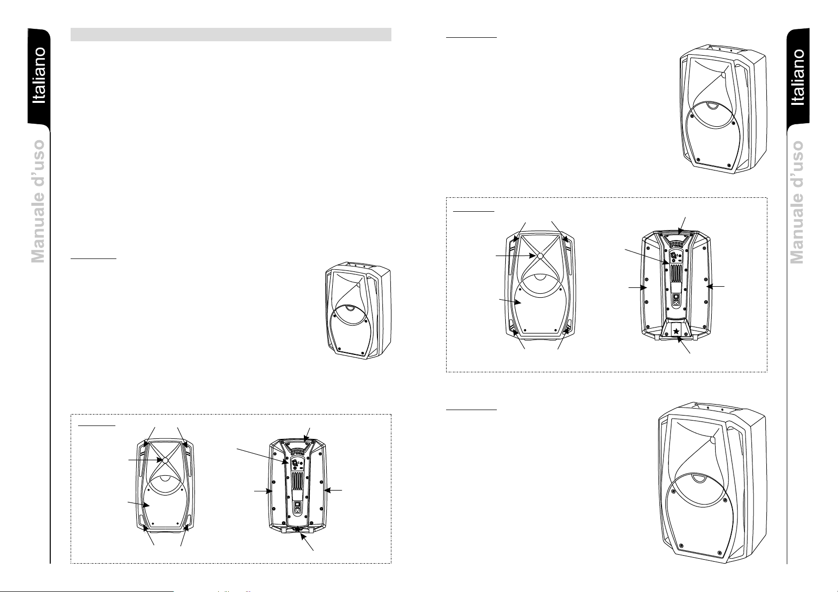
CROMO 8
M
Il diffusore attivo CROMO 8 è equipaggiato con un
amplificatore digitale
sezione bassi e20W (RMS)per la sezionealti.
Il diffusore a due vie biamplificato è equipaggiato con
woofer 8” (voice coil 1,5”) e driver al Neodimioda 1” (voice
coil 1”) caricatocon trombaasimmetrica 90°/70°x60°.
Il diffusore è in materiale plastico ed è dotato di una
maniglia superiore, rivestita in gomma, che ne facilita il
trasporto.
Nella parte inferiore del box è presente un supporto
piantana standard (D36mm).
Il diffusore è stato progettato anche per l’utilizzo in
appoggio come monitor(con angolazionedi 45°).
in grado di erogare 80W(RMS) perla
CROMO 10
Il diffusore attivo CROMO 10 è equipaggiato con un
amplificatore digitale in gradodi erogare140W (RMS) per
la sezione bassie 40W(RMS) per lasezione alti.
Il diffusore a due vie biamplificato è equipaggiato con
woofer 10” (voice coil 1,5”) e driver al Neodimio da 1”
(voice coil 1”) caricato con tromba asimmetrica
90°/70°x60°.
Il diffusore è in materiale plastico ed è dotato di una
maniglia superiore rivestita in gomma, che ne facilita il
trasporto.
Nella parte inferiore del box è presente un supporto
piantana standard (D36mm).
Il diffusore è stato progettato anche per l’utilizzo in
appoggio come monitor(con angolazionedi 45°).
C
r
o
m
o
o
n
a
i
l
a
t
I
Italiano
o
s
u
’
d
e
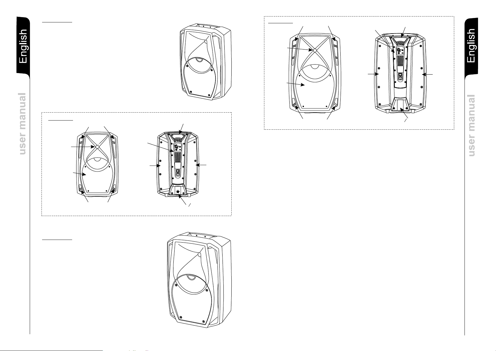
CROMO 10
CONDOTTI REFLEX
MANIGLIA
l
a
u
n
DRIVER
C
r
o
m
o
WOOFER
CONDOTTI REFLEX
AMPLIFICATORE
PIANO 45°
PIANO 45°
SEDE PIANTANA/STAFFA
∅ 36mm CON FISSAGGIO
a
M
CROMO 12
CROMO 8
DRIVER
WOOFER
1
CONDOTTI REFLEX
CONDOTTI REFLEX
MANIGLIA
AMPLIFICATORE
PIANO 45° PIANO 45°
SEDE PIANTANA/STAFFA
∅ 36mm CON FISSAGGIO
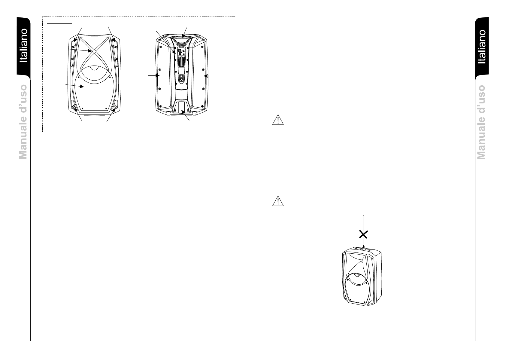
Il diffusore attivo CROMO 12 è equipaggiato con un
amplificatore digitale in grado di erogare 240W (RMS)per
la sezione bassie 60W(RMS) per lasezione alti.
Il diffusore a due vie biamplificato è equipaggiato con
woofer 12” (voice coil 2”) e un compression driver da 1”
(voice coil 1,5”) caricato con tromba asimmetrica
90°/70°x60°.
Il diffusore è in materiale plastico ed è dotato di una
maniglia superiore rivestita in gomma, che ne facilita il
trasporto.
Nella parte inferiore del box è presente un supporto
piantana standard (D36mm).
Il diffusore è stato progettato anche per l’utilizzo in
appoggio come monitor(con angolazionedi 45°).
C
r
o
m
o
2
Page 3
CROMO 12
o
n
a
i
l
a
t
I
Italiano
o
s
u
’
e d
l
a
u
n
a
COMANDI E FUNZIONI
M
3
CONDOTTI REFLEX
DRIVER
WOOFER
CONDOTTI REFLEX
Pannello Amplificatore (Rif. pag.23)
1) CONNETTORI “ Inputs”
Questi connettori possono essere utilizzati come ingressi bilanciati per il
collegamento di microfoni bilanciati o sbilanciati o di sorgenti audio a livello linea
(0dB) (es. Preamplificatore,mixer,registratore, lettore CD, strumento musicale,...)
Questi connettori sonocollegati inparallelo e possono essere utilizzati perrinviare il
segnale audio adaltri diffusori amplificati, registratori oamplificatori supplementari.
2) INDICATORELUMINOSO “Limiter”
Questo indicatore s’illumina di colore rosso per indicare l'intervento del circuito
limitatore interno, il quale evita la distorsione dell'amplificatore e protegge gli
altoparlanti da sovraccarichi.
3) INDICATORELUMINOSO “Ready”
Questo indicatore s'illumina di colore verde per indicare il corretto funzionamento
del diffusore. Nel normale funzionamento il led funge da Vu-Meter monitorando il
livello audio.
CONTROLLO “VOLUME”
4)
Questo controllo regola il volume in uscita dal diffusore.
Tale controllo non influisce sul livello del segnale rilanciato (link).
5) SELETTORE SENSIBILITA’ “Sensitivity”
Posizionare il selettore in LINE per l’utilizzo di una sorgente a livello linea (0dB) o
MIC per l’utilizzodi unmicrofono.
INTERRUTTORE GENERALE “POWER”
6)
L’interruttorepermette l’accensione e lo spegnimentodel diffusore.
7) PORTAFUSIBILE “FUSE”
Alloggio per fusibiledi rete.
PRESADI ALIMENTAZIONE “MAINS ”
8)
Consente la connessionedel cavodi alimentazione fornitoin dotazione.
AMPLIFICATORE
PIANO 45°
MANIGLIA
SEDE PIANTANA/STAFFA
∅ 36mm CON FISSAGGIO
PIANO 45°
PROTEZIONI
Griglie frontali
Visto l’utilizzo professionale di questi diffusori, i componenti sono protetti frontalmente da
una lamiera foratacon spessore1mm.
Raffreddamento
Il controllo termico è gestito dal DSP interno, che grazie ad un sensore controlla la
temperatura dell’amplificatore evitandoil surriscaldamentolimitandone il volumegenerale.
In caso di surriscaldamento (> 90°C) il volume decresce in funzione dell’aumento della
temperatura rendendo impercettibile la variazione.
Il corretto volume e tutte le funzioni verranno riprese automaticamente al raggiungimento
delle normali temperaturedi esercizio.
INSTALLAZIONE DEL DIFFUSORE
ATTENZIONE
Installare il diffusore in modo stabile e sicuro, così da evitare qualsiasi condizione di
pericolo per l’incolumitàdi personee strutture.
Per evitare condizioni di pericolo non sovrapporre fra loro più diffusori senza adeguati
sistemi di ancoraggio. Prima si sospendere il diffusore controllare tutti i componenti da
utilizzare, che non devono presentare danni, deformazioni, parti mancanti o danneggiate
che possono ridurrela sicurezzadell’installazione.
Nell’utilizzo all’aperto evitareluoghi espostialle intemperie.
Il diffusore vienefornito dalla ditta costruttricepredisposto perl’utilizzo :
- in appoggio (FIG.1)
- a pavimento (comemonitor) (FIG.2)
- su supporto piantana(FIG.3)
ATTENZIONE
Non utilizzare mai le maniglie per appendere il diffusore!
C
r
o
m
o
CLASSIFICAZIONE EMI
In accordo alle normative EN 55103, l'apparato è progettato e idoneo all'utilizzo in ambienti
Elettromagnetici E3 oinferiori (E2,E1).
o
n
a
i
l
a
t
I
Italiano
o
s
u
’
d
e
l
a
u
n
a
M
4
Page 4
o
n
a
i
l
a
t
I
Italiano
o
s
u
’
e d
l
a
u
n
a
M
CROMO 10 CROMO 12
2000 Hz, 24 dB/oct. 1900 Hz, 24 dB/ oct.
con monitor con monitor
XLR XLR
Bilanciato Bilanciato 6,3mm JACK Bilanciato
CROMO Series
DESCRIPTION
The “CROMO” series speakers use digital power amplifiers of last
generation
These highly efficient amplifiers provide high power with limited weight and dimension.
Thanks to the lowpower dissipated,the coolingof theamplifier moduledoes notrequire a
fan.
The digitalpreamplifier withDSP (Digital Signal Processing) controls the audio crossover
of the acoustic components, the frequency response, the limiter, and the phase
alignment.
The correct switch on of the amplifier is guaranteed by an initialization procedure; during
this test stage the LEDs ( LIMITER ), located on the amplifier module,stay
on together forapprox. 2sec.
At the end of the switch on procedure, on the amplifier module, the READY green LED
flashes slowly, when thereis signalabsence.
During normal operation the "READY”green LEDserves as Vu-meter monitoringthe audio
level riproduced.
The "LIMITER" red LED lights up to indicate that the internal limiter circuit has tripped to
prevent amplifier distortionand protects thespeakers againstoverloads.
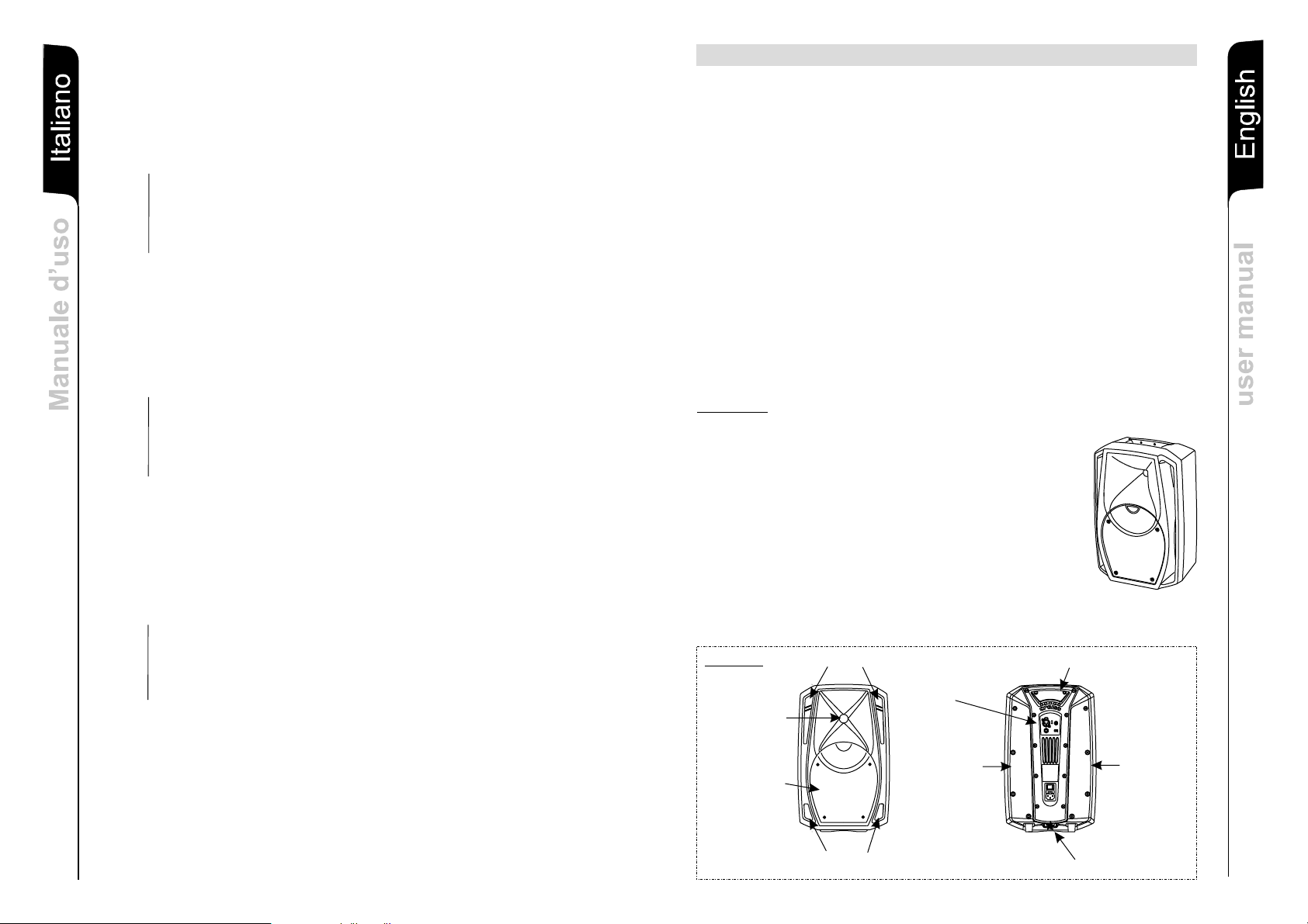
CROMO 8
The CROMO 8 bi-amped activespeaker is equipped with
digital amplifier delivering 80W RMS for the bass section
and 20W RMSfor thehigh frequency section.
The 2-way bi-amplified speaker is equipped with 8”
woofer (1,5” voice coil) and1” Neodymiumdriver (1” voice
coil) loaded with90°/70°x60° asymmetrichorn.
The speaker is made of plastic material, and is provided
with a top handle, rubber coated , which eases
transportation.
In the bottomof thebox thereis astandard polemount cup
(D36mm).
The speaker has been designed to be used also as stage
monitor (45° angled).
DIGIPACK.
“ ” and “READY”
multichannel
“”
C
r
o
m
o
h
s
i
l
g
n
E
English
l
a
u
n
a
m
r
e
s
u
1“ voice coil Neodmio 1“ voice coil Neodmio 1,5“ voice coil
CROMO 8
Trasformatore Toroidale
: Classe-D W/RMS 60 W/RMS
5
DATI TECNICI
Amplificatore e processore
Tipo alimentazione: Trasformatore Toroidale Trasformatore Toroidale
Pre-Amplificatore: 24bit 48KHz DSP 24bit 48KHz DSP 24bit 48KHz DSP
Tipo di amplificatore HF 20 W/RMS Classe-D 40 Classe-D
Tipo di amplificatore BF: Classe-D 80 W/RMS Classe-D 140 W/RMS Classe-D 240 W/RMS
Ventilazione: Convenzione, No ventola Convenzione, No ventola Convenzione, No ventola
Controlli/limitazioni: RMS, Picco, Termico RMS, Picco, Termico RMS, Picco, Termico
Frequenza X-over (taglio): 2100 Hz, 24 dB/oct.
Dati Audio
1x8“ Ceramico- 1,5“ voice coil 1x10“ Ceramico- 1,5“ voice coil 1x12“ Ceramico- 2“ voice coil
1x1“ compression driver 1x1“ compression driver 1x1“ compression driver
Risposta in frequenza -10 dB: 68 Hz - 20 kHz 65 Hz - 20 kHz 55 Hz - 20 kHz
Risposta in frequenza +-3 dB: 80 Hz - 19 kHz 70 Hz - 19 kHz 60 Hz - 19 kHz
SPL massimo: 118 dB 121 dB 126,5 dB
Woofer:
Driver:
6,3mm JACK 6,3mm JACK
Tromba (driver): 90°/70° x 60° 90°/70° x 60° 90°/70° x 60°
Input section
Ingressi/link: XLR femmina Bilanciato femmina Bilanciato femmina Bilanciato
Sensibilità in ingresso: -40dBu/0dBu (Mic/Line) -40dBu/0dBu (Mic/Line) -40dBu/0dBu (Mic/Line)
36 mm 36mm
Alimentazione: IEC, VDE IEC, VDE IEC, VDE
Equipaggiamento meccanico
Supporto piantana: 36mm
Maniglie: una superiore (in gomma) una superiore (in gomma) una superiore (in gomma)
7 12 kg 18,5 kg
(Lx H x P): 320 x 508 x 297mm 402 x 615 x 356mm
Angolo appoggio: 45° per monitor 45° 45°
Rete frontale: 1 mm Metallica 1 mm Metallica 1 mm Metallica
Dimensione 270 x 435 x 252mm
Peso: ,8 kg
Classe elettrica di protezione: II II II
Accessori opzionali : Custodia Custodia Custodia
CROMO 8
DRIVER
WOOFER
REFLEX HOLES
AMPLIFIER
PLANE 45°
REFLEX HOLES
HANDLE
∅ 36mm PEDESTAL/
BRACKET HOUSING
PLANE 45°
6
Page 5
CROMO 10
The CROMO 10 bi-amped active speaker is equipped
with digital amplifier delivering 140W RMS for the bass
section and 40WRMS forthe high frequency section.
sh
i
l
The 2-way bi-amplified speaker is equipped with 10”
g
woofer (1,5” voice coil) and 1” Neodymium driver(1” voice
coil) loaded with90°/70°x60°asymmetric horn.
En
English
The speaker is made of plastic material, and is provided
with a top handle, rubber coated , which eases
transportation.
In the bottomof thebox thereis a standard pole mount cup
(D36mm).
The speaker has been designed to be used also as stage
l
monitor (45° angled).
a
u
n
a
CROMO 10
REFLEX HOLES
r m
e
s
DRIVER
u
WOOFER
REFLEX HOLES
CROMO 12
The CROMO 12 bi-amped active speaker is equipped
with digital amplifier delivering 240W RMS for the bass
section and 60WRMS forthe high frequency section.
The 2-way bi-amplified speaker is equipped with 12”
woofer (2” voice coil) and 1” compression driver (1.5”
voice coil) loadedwith 90°/70°x60°asymmetrichorn.
The speaker is made of plastic material, and is provided
with a top handle, rubber coated , which eases
transportation.
In the bottom of the box there is a standard pole mount
cup (D36mm).
The speaker has been designed to be used also as stage
monitor (45° angled).
AMPLIFIER
PLANE 45°
HANDLE
O 36mm PEDESTAL/
BRACKET HOUSING
C
r
o
m
o
C
r
o
m
o
PLANE 45°
CROMO 12
DRIVER
WOOFER
REFLEX HOLES
REFLEX HOLES
COMMANDSAND FUNCTIONS
AMPLIFIER PANEL (Ref. page23)
1) “ Inputs” CONNECTORS
These balanced inputs can be used to connect balanced or unbalanced
microphones oraudio sources at line level(0dB) (eg. preamplifier,mixer, recorder,
CD player, musical instrument, ...).
The balancedconnector is connected in parallel and can be usedto send the audio
signal to otheramplified speakers,recorders or supplementaryamplifiers.
2) “Limiter” INDICATOR LIGHT
This indicator showsred toindicate that theinternal limitercircuit has tripped.
This prevents amplifierdistortion andprotects the speakersagainst overloads.
3)
“Ready” INDICATOR LIGHT
READY
The “ ” indicator light comes on green toindicate that theamplifier is switched
on and it is working properly.
monitoring the audiolevel riproduced.
4)
“VOLUME” CONTROL
The knob regulatesthe speaker´s volume.
This control doesnot affect the output “LINK”levels.
5)
“Sensitivity” SWITCH
Position the switch in LINE to use a line level source (0 dB) or MIC to use a
microphone.
6)
POWER SWITCH “POWER”
This switch canbe usedto switch thespeaker onand off.
7) FUSE CARRIER “FUSE”
Mains fuse housing.Replace onlywith identical value!
8)
POWER CABLE SOCKET“MAINS”
Used for connectingthe powercable supplied.
AMPLIFIER
PLANE 45°
During normal operationthe LEDserves asVu-meter
HANDLE
O 36mm PEDESTAL/
BRACKET HOUSING
PLANE 45°
sh
i
l
g
n
E
English
l
a
u
n
a
m
r
e
s
u
7
8
Page 6

PROTECTIONS
Front Grille
The speakers’s componentsin the box areprotected by1.0mm metal steelgrille.
sh
i
l
g
En
English
l
a
u
n
a
r m
e
s
u
Cooling
Thermal control is provided by the internal DSP, by means of one sensor, controls the
temperature of theamplifier, avoiding overheatingby limiting the overall volume.
In case of overheating (> 90°C) the volume decreases proportionally to the temperature
increase, making thechange unno
The correct volume and all the functions are automatically restored when standard
operating temperatures arereached.
LOUDSPEAKER INSTALLATION
WARNING
Make sure that the loudspeaker is securely installedin a stable position to avoid any
injuries or damagesto personsor property.
For safety reasons do notplace oneloudspeaker on top of anotherwithout proper fastening
systems. Before hanging the loudspeaker check all the components for damages,
deformations, missing ordamaged partsthat may compromisesafety duringinstallation.
If you usethe loudspeakersoutdoors avoid placesthat areexposed to badweather.
The loudspeaker hasthe followingmounting options:
- bookshelf (Fig. 1)
- floor (monitor) (Fig.2)
- on speaker stands(Fig.3).
ticeable.
ssion driver 1x1“ compression driver
one on top (with rubber)
h
s
i
l
g
n
E
English
l
a
u
n
a
m
r
e
s
u
WARNING
Never use the handles to hang the speaker!
C
r
o
m
o
EMI CLASSIFICATION
9
According to thestandards EN55103 this equipment is designed and suitable to operate inE3
(or lower E2,E1) Electromagneticenvironments.
TECHNICAL SPECIFICATION
Toroidal Transformer Toroidal Transformer
CROMO 8 CROMO 12CROMO 10
Class-D 20 W/RMS
Class-D 80 W/RMS
Convection, fan-free
Amp and processor
Power supply: Toroidal Transformer
HF amp: Class-D 40 W/RMS Class-D 60 W/RMS
Bass amp: Class-D 140 W/RMS Class-D 240 W/RMS
Pre-Amp: 24bit 48KHz DSP 24bit 48KHz DSP 24bit 48KHz DSP
Cooling: Convection, fan-free Convection, fan-free
Peak, RMS, Thermal Peak,RMS, Thermal Peak, RMS, Thermal
2100 Hz, 24 dB/oct
Limiter:
X-over frequency: 2000 Hz, 24 dB/oct. 1900 Hz, 24 dB/ oct.
Frequency response -10 dB: 68 Hz - 20 kHz 65 Hz - 20 kHz 55 Hz - 20 kHz
Frequency response +-3 dB: 80 Hz - 19 kHz 70 Hz - 19 kHz 60 Hz - 19 kHz
Max SPL: 118 dB 121 dB 126,5 dB
Audio Data
1“ voice coil Neodymium 1“ voice coil Neodymium 1,5“ voice coil
Bass/midrange woofer: 1x8“ Ceramic -1,5“ voice coil 1x10“ Ceramic -1,5“ voice coil 1x12“Cearamic -2“ voice coil
High frequency driver: 1x1“ compression driver 1x1“ compre
6,3mm JACK balanced 6,3mm JACK balanced
XLR fem. Balanced
6,3mm JACK balanced
Input section
Signal input/link: XLR fem. Balanced XLR fem. Balanced
Horn coverage: 90°/70° x 60° 90°/70° x 60° 90°/70° x 60°
x 435 x 252mm
-40dBu/0dBu (Mic/Line) -40dBu/0dBu (Mic/Line) -40dBu/0dBu (Mic/Line)
IEC, VDE
36 mm
Hardware
Input sensitivity:
Mains: IEC, VDE IEC, VDE
Handles (rubber): one on top (with rubber) one on top (with rubber)
Pole mount: 36 mm 36mm
,8 kg
45° both sides 45° both sides 45° both sides
1mm Metal
Monitor use angles:
Grille: 1 mm Metal 1 mm Metal
Dimensions (W x H x D): 270 320 x 508 x 297mm 402 x 615 x 356mm
Weight: 7 12 kg 18,5 kg
II II II
10
Electrical protection class:
Optional accessories: gig bag gig bag gig bag
Page 7

CROMO Serie
BESCHREIBUNG
sch
t
u
e
D
Deutsch
g
n
tu
i
e
l
n
Die Modelle der Serie “Cromo” verwenden digitale DIGIPACK Multichannel-KompaktVerstärker-Modulejüngster Generation.
Diese Verstärker mit großer Leistungsfähigkeit ermöglichen es,bei niedrigem Gewicht und
geringen Abmessungen hohe Ausgangsleistungen zu erzielen. Aufgrund der niedrigen
Leistungsverluste erfolgt die Kühlung des Verstärkermoduls durch Konvektion, wodurch
der Einsatz einesLüfters vermiedenwird.
Der digitale Vorverstärker mit DSP (Digital Signal Processing) trennt die Signalwege für
Woofer und Treiber,er regelt den Frequenzgang, denLimiter und die Phasenlage.
Das ordnungsgemäßeEinschalten desLautsprechers wird durch einen Initialisiervorgang
gewährleistet. Während dieser Testphase bleibt die LED (LIMITER und READY) auf dem
Verstärkermodulfür etwa 2 sausgeschaltet.
Am Ende des Einschaltvorgangs leuchtet die grüne "READY" LED und dient als VUMeter zur Überwachung des reproduzierten Audiopegels.
Die rote "Limiter" LED leuchtet,
welche die Verzerrung des Verstärkers verhindert und die Lautsprecher gegen
Überlastung schützt.
um dasAnsprechen derLimiterschaltung zusignalisieren,
a
s
g
CROMO 8
n
Der aktive bi-amp Lautsprecher CROMO 8 ist mit einem
u
Digital-Verstärker ausgestattet, der 80W (RMS) für den
n
Bassbereich und 20 W (RMS) für den Hochtonbereich
e
liefert.
i
Der Zwei-Wege-Lautsprecher ist mit einem Woofer 8”
d
(Voice Coil 1,5”) und einem Neodymtreiber (Voice Coil
e
1”) mit asymmetrischemHorn 90°/70°x60°ausgestattet.
B
Der Lautsprecher besteht aus Kunststoff und verfügt über
einen Griff auf der Oberseite mit Gummiüberzug, um den
Transporterleichtern.
An der Unterseite der Box ist ein StandardStänderflansch (D 36mm).
Der Lautsprecher ist auch für die Verwendung als Monitor
ausgelegt (Winkel 45°).
1”
CROMO 10
Der aktive bi-amp Lautsprecher CROMO 10 ist mit einem
Digital-Verstärker ausgestattet, der 140W (RMS) für den
Bassbereich und 40 W (RMS) für den Hochtonbereich
liefert.
Der Zwei-Wege-Lautsprecher ist mit einem Woofer 10”
(Voice Coil 1,5”) und einem 1” Kompressions-Treiber
(Voice Coil 1”) mit asymmetrischem Horn 90°/70°x60°
ausgestattet.
Der Lautsprecherbesteht aus Kunststoff und verfügt über
einen Griff auf der Oberseite mit Gummiüberzug, um den
Transporterleichtern.
An der Unterseite der Box ist ein StandardStänderflansch (D 36mm).
Der Lautsprecherist auch für die Verwendung als Monitor
ausgelegt (Winkel 45°).
CROMO 10
REFLEX / BELÜFTUNGSKANÄLE
VERSTÄRKERMODUL
GRIFF
C
r
o
m
o
sch
t
u
e
D
Deutsch
g
n
tu
i
e
l
n
a
s
g
n
TREIBER
u
n
e
45° FLÄCHE
WOOFER
C
r
o
m
o
REFLEX / BELÜFTUNGSKANÄLE
AUFNAHME STATIVFLANSCH O 36mm
45° FLÄCHE
i
d
e
B
11
CROMO 8
TREIBER
WOOFER
REFLEX / BELÜFTUNGSKANÄLE
VERSTÄRKERMODUL
REFLEX / BELÜFTUNGSKANÄLE
GRIFF
45° FLÄCHE 45° FLÄCHE
AUFNAHME STATIVFLANSCH 36mm∅
CROMO 12
Der aktive bi-amp Lautsprecher CROMO 12 ist mit einem
Digital-Verstärker ausgestattet, der 240W (RMS) für den
Bassbereich und 60W (RMS) für den Hochtonbereich
liefert.
Der Zwei-Wege-Lautsprecher ist mit einem Woofer 12”
(Voice Coil 2”) und einem 1” Kompressions-Treiber (Voice
Coil 1.5”) mit asymmetrischem Horn 90°/70°x60°
ausgestattet.
Der Lautsprecher besteht aus Kunststoff und verfügt über
einen Griff auf der Oberseite mit Gummiüberzug, um den
Transporterleichtern.
An der Unterseite der Box ist einStandard- Ständerflansch
(D 36mm).
Der Lautsprecher ist auch für die Verwendung als Monitor
ausgelegt (Winkel 45°).
C
r
o
m
o
12
Page 8

CROMO 12
sch
t
u
e
D
Deutsch
g
n
tu
i
e
l
n
a
s
g
BEDIENELEMENTE UND FUNKTIONEN
n
u
n
e
i
d
e
B
13
REFLEX / BELÜFTUNGSKANÄLE
VERSTÄRKERMODUL
TREIBER
45° FLÄCHE
WOOFER
REFLEX / BELÜFTUNGSKANÄLE
BEDIENELEMENTE DES VERSTÄRKERS (
1) EINGANGSBUCHSEN “INPUTS”
Diese symmetrischen Eingänge können zumAnschließen vonsymmetrischen oder
unsymmetrischen Mikrofonen oder Audioquellen mit Line-Pegel (0dB) (z.B.
Vorverstärker, Mixer, Recorder, CD-Player, Musikinstrument usw.) verwendet
werden.
Der Parallelanschluss kann dazu verwendet werden, das ankommende
Audiosignal an andere Aktiv-Lautsprecher, Recorder oder zusätzliche Verstärker
weiter zu leiten.
2) LED “LIMITER”
Diese rote LED leuchtet auf, um das Ansprechen der Limiterschaltung zu
signalisieren, welche die Verzerrung des Verstärkers verhindert und die
Lautsprecher gegen Überlastung schützt.
3)
LED “READY”
Die LED “READY” leuchtet grün, wenn der Verstärker eingeschaltet ist und
ordnungsgemäß funktioniert. Am Ende des Einschaltvorgangs leuchtet LED und
dient als VU-Meterzur Überwachungdes reproduzierten Audiopegels.
4) BEDIENUNGSELEMENT “VOLUME”
Der Drehknopf regeltdie Lautstärkedes Lautsprechers.
Die Einstellung des Volumenreglershat keinerlei Wirkung auf denAusgang " LINK",
Das Eingangssignal wirddurchgeschleift.
5) EMPFINDLICHKEITSWAHLSCHALTER "SENSITIVITY"
Den Wahlschalter für den Anschluß einer Quelle mit Line-Pegel (0dB)auf LINEund
für den Gebraucheines Mikrofonsauf MIC schalten.
6) NETZSCHALTER“POWER”
Dieser Schalter dientzum EIN- undAUS-Schalten derLautsprecherbox.
7) "FUSE" SICHERUNGSHALTER
Integrierte Netzsicherung. Bei Defekt nur durch eine identische Sicherung
ersetzen!
ANSCHLUSS NETZKABEL “MAINS”
8)
Netzanschluss zur Aufnahme des mitgelieferten Stromkabels.
AUFNAHME STATIVFLANSCH O 36mm
Referenzseite 23
HANDGRIFF
)
45° FLÄCHE
SCHUTZ
Frontgitter
Zum des professionellen Einsatzes dieser Lautsprecher sind die
Lautsprecherkomponenten durch einLochblech mit1mm Stärke geschützt.
Kühlung
Die Temperaturkontrolle wird durch den DSP im Inneren gesteuert, der mittels Sensoren
die Temperatur des Verstärkers prüft, wodurch die Überhitzung vermieden und die
Lautstärke begrenzt wird.
Bei einer Überhitzung (> 90 °C) verringert sich die Lautstärke in Abhängigkeit des
Temperaturanstiegs, wodurch dieVeränderung nicht wahrnehmbarist.
Die vorherige Lautstärke und alle Funktionen werden automatisch nach Erreichen der
normalen Betriebstemperaturen wiederhergestellt.
INSTALLATION DES LAUTSPRECHERS
ACHTUNG
Den Lautsprecher auf eine stabile und sichere Art und Weise installieren, um jede
Gefahr für Personenoder Sachschädenzu vermeiden.
Um gefährliche Situationen zu vermeiden, nie mehrere Lautsprecher ohne angemessene
Abspannsysteme aneinander anschließen.
Bevor man den Lautsprecher aufhängt, alle Teile kontrollieren, sie sollen keine Schäden
oder Verformungen, keine fehlenden oder beschädigten Teile haben, die eine sichere
Installation beeinträchtigen könnten.
Bei Verwendung im Freien sollte man darauf achten, das die Lautsprecher vor
Witterungseinflüssen wie Sturm,Regen, Hagel,Schnee, usw. geschützt sind.
Der Lautsprecher istfür folgende Verwendungen geeignet:
- auf einer Distanzstange(BILD 1)
- auf dem Boden(als Monitor)(BILD 2)
- auf einem Ständer(BILD 3).
VORSICHT
Hängen Sie den Lautsprecher nie an den Griffen auf!
C
r
o
m
o
EMV Einstufung
Entsprechend der Norm EN 55103 ist diese Gerät entwickelt um in E3 (oder E2, E1)
elektromagnetischen Umgebungen zuarbeiten
sch
t
u
e
D
Deutsch
g
n
tu
i
e
l
n
a
s
g
n
u
n
e
i
d
e
B
14
Page 9

sch
t
u
e
D
Deutsch
g
n
tu
i
e
l
n
a
s
g
n
u
n
e
i
d
e
CROMO 10 CROMO 12CROMO 8
B
2000 Hz, 24 dB/oct. 1900 Hz, 24 dB/ oct.
Konvektion
x 508 x 297mm
Schutzhülle
CROMO Series
DESCRIPTION
Les de la série “CROMO” utilisent modules amplificateur numérique à canaux
diffuseur
multiples DIGIPACK de dernièregénération.
Ces amplificateurs à haute efficacité permettent d'obtenir des puissances de sorties
élevées, tout en ayant des encombrements réduits. Grâce à unepuissance dissipéefaible,
le refroidissement du module amplificateur se fait de façon statique, évitant le recours à la
vanne.
Le préamplificateur numérique avec traitement numérique du signal DSP (Digital Signal
Processing) gère le croisement audio des composants acoustiques, la réponse en
fréquence, le limiteur, et l'alignement de phase.
La puissance douce de l'enceinte est garanti par la procédure d'initialisation, au cours de
cette phase de test, à la fois la LED LIMITER " et " READY "sont allumés en même temps
pendant environ 2secondes .
Au terme de la procédure de démarrage, sur le module d'amplification, la "READY" LED
verte clignote lentement,en l'absencede signal.
En fonctionnement normal de la "READY" LED verte actes de VU-mètre surveille le
niveau audio reproduit.
Les rouges "LIMITER" LED s'allume, pour indiquer l'intervention du circuit limiteur
interne qui évite la distorsion de l'amplificateur et protège les haut-parleurs contre les
surcharges.
CROMO 8
Le diffuseur bi-amplifier actif CROMO 8 est équipé d'un
amplificateur numérique capable de distribuer80W (RMS)
pour la section basses et 20W (RMS) pour la section
aigues.
Le diffuseur àdeux voies bi-amplifié est équipéde woofer
8” (voice coil 1,5”) et driver au Néodyme de 1” (voice coil
1”) chargé avecprofil asymétrique 90°/70°x60°
Le diffuseur est en matière plastique, également doté
d'une poignée supérieure, revêtues de caoutchouc, pour
en faciliter letransport.
Dans la partie inférieure de la box, figure un support sur
pied standard (D36mm).
Le diffuseur a également été conçu pour l'utilisation en
soutien comme moniteur(angle de 45°).
C
r
o
m
o
Français
s
e
u
q
i
n
h
c
e
t
s
e
u
q
ti
s
i
r
te
c
a
r
a
C
15
TECHNISCHE DATEN
Class-D 20 W/RMS
Class-D 80 W/RMS
Ringkerntransformator
Verstärkerund Prozessor
Netzteil: Ringkerntransformator Ringkerntransformator
Pre-Amp: 24bit 48KHz DSP 24bit 48KHz DSP 24bit 48KHz DSP
Peak,RMS, Thermal Peak,RMS, Thermal Peak,RMS, Thermal
: Konvektion Konvektion
Kühlung
Verstärker Typ Höhen : Class-D 40 W/RMS Class-D 60 W/RMS
Limiter:
Verstärker Typ Bässe: Class-D 140 W/RMS Class-D 240 W/RMS
1x1“ Kompressionstreiber 1x1“ Kompressionstreiber 1x1“ Kompressionstreiber
Audio-Daten
X-over Frequenz: 2100 Hz, 24 dB/oct.
Frequenzgang -10 dB: 68 Hz - 20 kHz 65 Hz - 20 kHz 55 Hz - 20 kHz
Frequenzgang +-3 dB: 80 Hz - 19 kHz 70 Hz - 19 kHz 60 Hz - 19 kHz
Schalldruck (max SPL): 118 dB 121 dB 126,5 dB
Woofer: 1x8“ Keramik - 1,5“ voice coil 1x10“ Keramik - 1,5“ voice coil 1x12“ Keramik - 2“ voice coil
Treiber:
Symmetrisch 6,3mm Symmetrisch 6,3mm Symmetrisch
1“ voice coil Neodym 1“ voice coil Neodym 1,5“ voice coil
XLR fem. Symmetrisch Symmetrisch Symmetrisch
-40dBu/0dBu (Mic/Line) -40dBu/0dBu (Mic/Line) -40dBu/0dBu (Mic/Line)
IEC, VDE
6,3mm
Eingangssektion
Abstrahlcharakteristik: 90°/70° x 60° CD Horn 90°/70° x 60° CD Horn 90°/70° x 60° CD Horn
Signal input/link: XLR fem. XLR fem.
Input Sensitivity:
Netzbuchse: IEC, VDE IEC, VDE
Einer oben Einer oben Einer oben
36 mm 36mm
Hardware
Ständerflansch: 36 mm
Winkel für Monitor : 45° biede Seiten 45° biede Seiten 45° biede Seiten
Griffe:
1mm Metal Metall Metall
7 12 kg 18,5 kg
Gitter: 1mm 1mm
Maße (B x H x T): 270 x 435 x 252mm 320 402 x 615 x 356mm
Gewicht: ,8 kg
Elektrische Schutzklasse: II II II
Optionales Zubehör: Schutzhülle Schutzhülle
CROMO 8
DRIVER
WOOFER
ÉVENTS REFLEX
ÉVENTS REFLEX
PANNEAU
AMPLIFICATEUR
CÔTÉ 45°
POIGNEÉ
SIÉGE PIED/ÉTRIER
∅ 36mm
CÔTÉ 45°
16
Page 10

CROMO 10
Le diffuseur bi-amplifier actif CROMO 10 est équipé d'un
amplificateur numérique capable de distribuer 140W
(RMS) pour la section basses et 40W (RMS) pour la
section aigues.
Le diffuseur à deux voies bi-amplifié est équipé de woofer
10” (voice coil 1,5”) et driver au Néodyme de 1” (voice coil
1”) chargé avecprofil asymétrique90°/70°x60°.
Le diffuseur est en matière plastique, également doté
Français
d'une poignée supérieure, revêtues de caoutchouc, pour
en faciliter letransport.
Dans la partie inférieure de la box, figure un support sur
s
pied standard (D36mm).
e
Le diffuseur a également été conçu pour l'utilisation en
u
soutien comme moniteur(angle 45°)
q
i
n
h
CROMO 10
c
s te
e
u
q
ti
s
i
r
te
c
a
r
a
C
CROMO 12
Le diffuseur bi-amplifier actif CROMO 12 est équipé d'un
amplificateur numérique capable de distribuer 240W
(RMS) pour la section basses et 60W (RMS) pour la
section aigues.
Le diffuseur à deux voies bi-amplifié est équipé de woofer
12” (voice coil 2”) et de 1” (voice
coil 1.5”) chargéavec profilasymétrique 90°/70°x60°
Le diffuseur est en matière plastique, également doté
d'une poignée supérieure, revêtues de caoutchouc, pour
en faciliter letransport.
Dans la partie inférieure de la box, figure un support sur
pied standard (D36mm).
Le diffuseur a également été conçu pour l'utilisation en
soutien comme moniteur(angle 45°).
17
DRIVER
WOOFER
ÉVENTS REFLEX
ÉVENTS REFLEX
un driver de compression
PANNEAU
AMPLIFICATEUR
CÔTÉ 45°
POIGNEÉ
SIÉGE PIED/ÉTRIER
∅ 36mm
C
r
o
m
o
CROMO 12
DRIVER
C
r
o
m
o
ÉVENTS REFLEX
PANNEAU
AMPLIFICATEUR
POIGNEÉ
Français
CÔTÉ 45°CÔTÉ 45°
WOOFER
s
e
u
q
i
n
ÉVENTS REFLEX
SIÉGE PIED/ÉTRIER
∅ 36mm
h
c
e
t
s
18
e
u
q
ti
s
i
r
te
c
a
r
a
C
CÔTÉ 45°
COMMANDES ET FONCTIONS
FAÇADE AMPLIFICATEUR
CONNECTEURS D'ENTRÉE
1) “Inputs”
Ces Entrées symétriques peuvent être utilisées pour la connexion de microphones
symétriques ou asymétriques ou de sources au niveau ligne (0dB) (par ex.
préamplificateur, table de mixage, platine cassette, lecteur CD, instrument de
musique, ...).
La sortie est reliée en parallèle à l'entrée et peut être utilisée pour transmettre un
signal audio en entrée à un autre diffuseur amplifié, à un enregistreur ou à un
amplificateur supplémentaire.
2) INDICATEURLUMINEUX “Limter”
Cet indicateur s'allume de couleur rouge pour indiquer l'intervention du circuit
limiteur interne qui évite la distorsion de l'amplificateur et protège les haut-parleurs
contre les surcharges
INDICATEURLUMINEUX “Ready”
3)
L'indicateur lumineux “READY” s'allume de couleur vert pour indiquer que le
diffuseur est allumé et le fonctionnement correct de l'amplificateur. En
fonctionnement normal la LED actes de VU-mètre surveille le niveau audio
reproduit.
4)
CONTRÔLE "Volume"
La commande permetde réglerle volume dudiffuseur.
Ce contrôle n'influepas surle niveau dela sortie"LINK".
SÉLECTEUR SENSIBILITÉ “Sensitivity”
5)
Positionner le sélecteur sur LINE pour utiliser une source au niveau ligne (0dB) ou
sur MIC pourutiliser unmicrophone.
INTERRUPTEUR “POWER”
6)
L’interrupteurpermet d’allmer et d’éteindrel’enceinte.
BLOC À FUSIBLES“FUSE”
7)
Logement pour lefusible desecteur.
8) PRISE POUR LE FILD’ALIMENTATION “MAINS”
Elle permet debrancher lecordon d’alimentaion fournien dotation.
(Référence page 23)
Page 11

PROTECTION
Grilles frontales
Etant donné l'utilisation professionnelle de ces diffuseurs, les composant sont protégés
frontalement par unetôle percéed'une épaisseur de1 mm.
Refroidissement
Le contrôle thermique est géré par le DSP interne, qui, grâce à une capteurs, contrôle la
température de l'amplificateur et de l'alimentation pour éviter la surchauffe en limitant le
Français
volume général. En cas de surchauffe (> 90°C), le volume décroît en fonction de
l'augmentation de latempérature, cequi rend lavariation imperceptible.
Le volume correct ainsique toutesles fonctionsseront automatiquementreprises, unefois
que les températuresde fonctionnementnormales seront atteintes.
s
e
IINSTALLATION DU DIFFUSEUR
u
q
i
n
h
c
s te
e
u
q
ti
s
i
r
te
c
a
r
ATTENTION
Installer le diffuseur de façon stable et sûre afin d'éviter toute condition de danger
pour l'intégrité despersonnes etdes structures.
Afin d'éviter les conditions de danger, ne pas superposer entre eux plusieurs diffuseurs
sans systèmes d'ancrage appropriés. Avant de suspendre le diffuseur, contrôler tous les
composants à utiliser, qui ne doivent présenter aucun dommage, aucune déformation ou
partie manquante ou abimée qui seraient susceptibles de réduire la sécurité de
l'installation.
Lors de l'utilisationen espaceaérés, éviter leslieux exposésaux intempéries.
Le diffuseur estfourni par l'entreprise quile fabriqueet il estprédisposé pourl'utilisation:
- en appui (Fig.1)
- au sol (comme
- sur support mât(Fig.3).
ATTENTION
Ne jamais utiliser les poignées pour suspendre l'enceinte!
écran) (Fig.2)
a
C
CROMO 10 CROMO 12
Trasformateurtoroïdal Trasformateurtoroïdal
Class-D 40 W/RMS Class-D 60 W/RMS
Class-D 140 W/RMS Class-D 240 W/RMS
2000 Hz, 24 dB/oct. 1900 Hz, 24 dB/ oct.
Peak,RMS, Thermal Peak,RMS, Thermal
Symétrique
-40dBu/0dBu (Mic/Line) -40dBu/0dBu (Mic/Line)
IEC, VDE IEC, VDE
6,3mm JACK
45° 45°
Français
s
e
u
q
i
n
h
c
e
t
s
e
u
q
ti
s
i
r
te
c
a
r
a
C
19
C
r
o
m
o
CLASSIFICATION EMI
En accord aux les normes EN 55103, l'équipement est conçu et convenable pour une
utilisation en environnementélectromagnétique E3ou inferieur (E2,E1).
CROMO 8
HF: Class-D 20 W/RMS
: Convection, no fan Convection, no fan Convection, no fan
fréquence
Amplificateur
DONNES TECHINIQUES
Amplificateur et processeur
ypologie amplificateur B
Typologie amplificateur
Typologie de pouvoir: Trasformateurtoroïdal
Refroidissement
Pre- : 24bit 48KHz DSP 24bit 48KHz DSP 24bit 48KHz DSP
T F: Class-D 80 W/RMS
Limiteur: Peak,RMS, Thermal
X-over : 2100 Hz, 24 dB/oct.
Les données audio
1“ voice coil Neodymium 1“ voice coil Neodymium 1,5“ voice coil
1x1“ compression driver 1x1“ compression driver 1x1“ compression driver
: 118 dB 121 dB 126,5 dB
-3 dB: 80 Hz - 19 kHz 70 Hz - 19 kHz 60 Hz - 19 kHz
-10 dB: 68 Hz - 20 kHz 65 Hz - 20 kHz 55 Hz - 20 kHz
: 90°/70° x 60° 90°/70° x 60° 90°/70° x 60°
Réponse en fréquence
Réponse en fréquence+
Pression sonore (max SPL)
Woofer: 1x8“ Ceramic - 1,5“ voice coil 1x10“ Ceramic - 1,5“ voice coil 1x12“ - 2“ voice coil
Driver:
Dispersion
Section d'entrée
Symétrique Symétrique
Symétrique Symétrique Symétrique
6,3mm JACK 6,3mm JACK
XLR fem.
-40dBu/0dBu (Mic/Line)
IEC, VDE
: 36 mm 36mm
Signal input/link: XLR fem. XLR fem.
Entrée sensibilité:
Alimentation:
Siége pied/étrier 36 mm
Poigneé: un au haut (avec gomme) un au haut (avec gomme) un au haut (avec gomme)
Matériel
x 435 x 252mm
,8 kg
7 12 kg 18,5 kg
1mm Métal Métal Métal
Grille: 1mm 1mm
Dimensions (W x H x D): 270 320 x 508 x 297mm 402 x 615 x 356mm
Poids:
Utilissation au sol: 45° écran écran écran
Classe de protection électrique: II II II
Accessoires en option: Couvrir Couvrir Couvrir
20
Page 12

AMPLIFICATORE - AMPLIFIER
- AMPLIFICATEURSVERSTÄRKER
SCHEMA A BLOCCHI - BLOCK DIAGRAM
BLOCKSCHALTBILD - SCHEMAS FONCTIONNELS
CROMO 8
AMPLFIER CROMO
MAINS
L
N
FUSE
POWER
SWITCH
TRANSFORMER
INTERNAL
POWER
SUPPLY
100W
2
PUSH
1
NPUTS
READY
VOLUMELIMITER
SENSITIVITY
LINE
0dB
MAX0
MIC
-40dB
3
4
5
INPUTS
SENSITIVITY
VOLUME
DIGIPACK 200
Class D
DSP
igital ignal rocessingDSP
Class D
LIMITER READY
DRIVER
WOOFER
CROMO 10
“CAUTION”
TO PREVENT ELECTRICALSHOCK
DO NOT REMOVE COVER
“AVIS”
RISQUE DE CHOCH ELECTRIQUE
NE PAS OUVRIR
CROMO
220-240V~ 50-60Hz
110-120V~ 50-60Hz
FUSE MAINSPOWER
I
Made in P.R. of China
MODULE POWER
CONSUMPTION
Internal voltage setup
0
AMPLFIER CROMO
MAINS
INPUTS
L
N
FUSE
SENSITIVITY
POWER
SWITCH
TRANSFORMER
INTERNAL
POWER
SUPPLY
DIGIPACK 200
6
DSP
7
VOLUME
igital ignal rocessingDSP
200W
DRIVER
Class D
WOOFER
8
LIMITER READY
Class D
2221
Page 13

CROMO 12
MAINS
L
N
INPUTS
FUSE
SENSITIVITY
POWER
SWITCH
TRANSFORMER
VOLUME
AMPLIFIER CROMO
INTERNAL
POWER
SUPPLY
DIGIPACK 400
DSP
igital ignal rocessingDSP
400W
Class D
Class D
Class D
DRIVER
WOOFER
60°
ANGOLO DI COPERTURA TROMBA / HORN COVERAGE
ANGLE
HOCHTONHORN ABSTRAHLWINKEL / ANGLE DE COUVERTURE COTE
70°
C
r
o
m
o
90°
COLLEGAMENTI
CONNECTIONS
ANSCHL
ÜSSE
BRANCHEMENTS
Funzionamento sbilanciato con
connettore jack 1/4” (6,3mm)
Unbalanced use of stereo 1/4” jack plug
Punta = Segnale
Tip = Signal
Punta Gambo
Tip Sleeve
Funzionamento sbilanciato con
connettore XLR
Unbalanced use with XLR connectors
2
3
1
Ingresso
XLR - maschio
Input
XLR - male
Gambo=Schemo/Massa/Terra
Sleeve=Screen/Ground/Earth
Pin 2 = Positivo/Caldo/Fase +VE
Pin 2 = Positive/Hot/+VE Phase
Pin 1 =Schermo/Terra/Massa
Pin 1 =Screen/Ground/Earth
Pin 3 = Connesso al Pin 1
Pin 3 = Link to Pin 1
Class D
LIMITER
READY
Funzionamento bilanciato con
connettore jack 1/4” (6,3mm)
Balanced use of stereo 1/4” jack plug
Punta = Positivo/Caldo/Fase +VE
Tip = Positive/Hot/+VE Phase
Punta
Ring
Tip
Funzionamento bilanciato con
connettore XLR
Balanced use with XLR connectors
2
3
1
Ingresso
XLR - maschio
Input
XLR - male
Anello = Negativo/Freddo/Fase -VE
Ring=Negative/Cold/-VE Phase
Gambo=Schemo/Massa/Terra
Sleeve=Screen/Ground/Earth
Anello
Gambo
Sleeve
Pin 2 = Positivo/Caldo/Fase +VE
Pin 2 = Positive/Hot/+VE Phase
Pin 1 =Schermo/Terra/Massa
Pin 1 =Screen/Ground/Earth
Pin 3 =Negativo/Freddo/Fase -VE
Pin 3 =Negative/Cold/-VE Phase
70°
90°
Long throw
Near field
2423
Page 14

DIMENSIONI / DIMENSIONS
ABMESSUNGEN / DIMENSIONS
DIMENSIONI / DIMENSIONS
ABMESSUNGEN / DIMENSIONS
CROMO 8
C
r
o
m
o
CROMO 10
C
r
o
m
o
CROMO 12
C
r
o
m
o
435 mm
270 mm
45°
m
o
o
r
C
m
o
o
r
C
m
o
o
r
C
508 mm
320 mm
297 mm
252 mm
615 mm
45°
402 mm
356 mm
45°
2625
Page 15

UTILIZZO IN APPOGGIO
SUPPORTED USE
ANWENDUNG
UTILISATION EN APPUI
C
r
o
m
o
UTILIZZO A PAVIMENTO (MONITOR)
FLOOR USES (MONITOR)
VERWENDUNG AUF DEM BODEN (MONITOR)
UTILISATION AU SOL (ÉCRAN)
C
r
o
m
o
C
r
o
m
o
Fig. 1
Fig. 2
SUPPORTO PIANTANA STANDARD (D36M)
STANDARD STAND (D36MM)
STANDARD-HOCHSTÄNDERFLANSCH
(D36MM)
SUPPORT STANDARD (D36MM)
m
o
o
r
C
MAX 140 cmMAX 140 cm
C
r
o
m
C
r
o
m
o
o
Fig. 3
2827
 Loading...