

DBI SALA 2200401, 2200403, 2200402, Vacuum Anchor Horizontal Lifeline System, 2200405 User Instruction
...Page 1

Instructions for the following series products:
Vacuum Anchor HLL System
(See back page for specific model numbers.)
User Instruction Manual
Vacuum Anchor
Horizontal Lifeline System
This manual is intended to be used as part of an
employee training program as required by OSHA.
WARNING: This product is part of a personal fall arrest system. The user must f ollow the manufacturer’ s instructions for
each component of the system. These instructions must be provided to the user of this equipment. The user must read
and understand these instructions before using this equipment. Manufacturer’s instructions must be f ollowed for proper
use and maintenance of this equipment. Alterations or misuse of this equipment, or failure to follow instructions, may result
in serious injury or death.
IMPORTANT: If you hav e questions on the use, care, or suitability of this equipment for your application, contact DBI/SALA.
IMPORTANT: Record the product identification information from the ID label in the inspection and maintenance log in
section 9.0 of this manual.
1.0 APPLICATION
1.1 PURPOSE: The V acuum Anchor Horizontal Lifeline System is designed f or use as an anchoring means for one or
two personal fall arrest systems. Use the V acuum Anchor Horizontal Lif eline System where horizontal mobility and
fall protection are required. The system is used in conjunction with v acuum anchors.
1.2 LIMITATIONS: The following limits apply to the installation and use of the Vacuum Anchor Horizontal Lif eline
System. Other limitations may apply:
IMPORTANT : OSHA regulations state that horizontal lif elines shall be installed and used under the supervision of a
qualified person (see below for definition) as part of a complete personal fall arrest system that maintains a saf ety factor
of at least two .
Qualified Person: An individual with a recognized degree or prof essional certificate, and extensive knowledge and
experience in the subject field, who is capable of design, analysis, evaluation, and specification in the subject work,
project, or product. Refer to OSHA 1910.66, 1926.32, and 1926.502.
A. HORIZONT AL LIFELINE SPAN: The maximum span distance is 40 ft. (12.2 m) f or a single span system. F or
multiple span systems, the maximum span distance is 80 ft. (24.4 m) with a maximum subspan length of 40 ft
(12.2 m). The span length must be reduced when clear ance is limited. See section 3.0 f or clearance information.
B. ANCHORAGE STR UCTURE: The surf ace to which the V acuum Anchors are attached must meet the limitations
and strength requirements specified in instruction 5902157.
C. SYSTEM CAP A CITY : The maximum capacity of the Vacuum Anchor Horizontal Lif eline is two persons. The
maximum weight of each person, including tools and clothing, is 310 lbs. (141 kg).
1
© Copyright 2005, DB Industries, Inc.
Page 2

Figure 1 - Typical Single Span Horizontal Lifeline Installation
2
Page 3
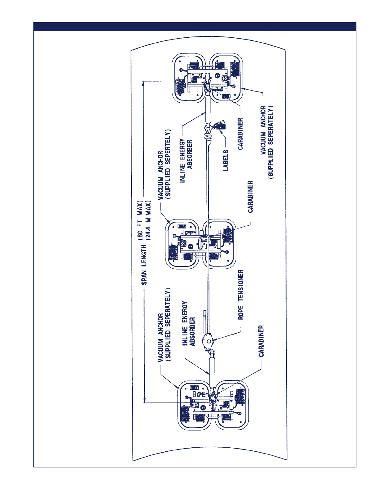
Figure 2 - Typical Multiple Span Horizontal Lifeline Installation
3
Page 4

D. CONNECTING SUBSYSTEM: A DBI/SALA Force 2 Energy Absorbing Lanyard must be used as the connecting
subsystem with the Vacuum Anchor Horizontal Lifeline .
E. FREE FALL: Whenev er possible , locate the horizontal lifeline such that the user is restrained from reaching a
fall hazard. If rigging as a restraint system is not possible, rig system such that the potential free fall is
minimized by positioning the horizontal lifeline as high and as far from the edge as possible, and by limiting the
lanyard length. P otential free f all m ust not e xceed 11 ft. (3.4 m).
F. SWING F ALLS: Swing falls occur when a w orker is positioned to the side of a horizontal lif eline when a fall
occurs. The force of striking an object in a swing f all may cause serious injury or death. Swing falls can be
minimized by working as close to the horizontal lifeline as possible.
G. F ALL CLEARANCE: There must be sufficient clearance below the w orker to arrest a fall bef ore striking the lower
level or obstruction. See section 3.0 for required clearance information.
H. BODY SUPPOR T : The Vacuum Anchor Horizontal Lif eline must be used as part of a personal fall arrest system
incorporating a full body harness.
I. ENVIRONMENT AL HAZARDS: Use of this equipment in areas with environmental hazards ma y require
additional precautions to reduce the possibility of injury to the user or damage to the equipment. Hazards may
include, but are not limited to; heat, chemicals, corrosive environments, high voltage power lines, gases, moving
machinery, and sharp edges. Contact DBI/SALA if y ou have questions about using this equipment where
environmental hazards exist.
J. TRAINING: This equipment must be installed and used by persons trained in its correct application and use . See
section 4.0.
1.3 APPLICABLE ST ANDARDS: Ref er to national standards, including ANSI Z359.1 and local, state, and f ederal
(OSHA 1910.66 and 1926.502) requirements for more information on personal fall arrest systems and associated
components.
2.0 SYSTEM REQUIREMENTS
2.1 PERSONAL F ALL ARREST SYSTEM COMPONENTS: The V acuum Anchor horizontal lif eline must be used with
DBI/SALA approved components and subsystems. Substitutions or replacements made with non-approved
components or subsystems may jeopardize compatibility of equipment and may effect the safety and reliability of
the complete system. Personal fall arrest components used with this system must meet all applicab le OSHA and
ANSI requirements. A full body harness must be used with this system.
2.2 PERSONAL FALL ARREST SYSTEM CONNECT ORS: Connectors are considered to be compatib le with
connecting elements when they have been designed to work together in such a way that their sizes and shapes do
not cause their gate mechanisms to inadvertently open regardless of how they become oriented. Contact DBI/SALA
if you have an y questions about compatibility.
Connectors (hooks, carabiners, and D-rings) must be capab le of supporting at least 5,000 lbs. (22kN). Connectors
must be compatible with the anchorage or other system components. Do not use equipment that is not compatible.
Non-compatible connectors may unintentionally disengage. See Figure 3. Connectors must be compatible in size,
shape, and strength. Self locking snap hooks and carabiners are required by ANSI Z359.1 and OSHA.
2.3 MAKING CONNECTIONS: Only use self-locking snap hooks and carabiners with this equipment. Only use
connectors that are suitable to each application. Ensure all connections are compatible in size, shape and strength.
Do not use equipment that is not compatible. Ensure all connectors are fully closed and locked.
DBI/SALA connectors (snap hooks and carabiners) are designed to be used only as specified in each product’s
user’s instructions. See Figure 4 f or inappropriate connections. DBI/SALA snap hooks and carabiners should not be
connected:
A. To a D-ring to which another connector is attached.
B. In a manner that would result in a load on the gate.
4
Page 5

Figure 3 - Unintentional Disengagement (Roll-out)
If the connecting element that a snap hook (shown) or carabiner attaches to is undersized or irregular in shape,
a situation could occur where the connecting element applies a force to the gate of the snap hook or carabiner .
This force may cause the gate (of either a self-locking or a non-locking snap hook) to open, allowing the snap
hook or carabiner to disengage from the connecting point.
Small ring or other
non-compatibly
shaped element
1. Force is applied to the
snap hook.
2. The gate presses against
the connecting ring.
3. The gate opens allowing the
snap hook to slip off.
NOTE: Large throat opening snap hooks should not be connected to standard size D-rings or similar objects which will
result in a load on the gate if the hook or D-ring twists or rotates. Large throat snap hooks are designed for use on fixed
structural elements such as rebar or cross members that are not shaped in a way that can capture the gate of the hook.
C. In a false engagement, where
Figure 4 - Inappropriate Connections
features that protrude from the
snap hook or carabiner catch on
the anchor and without visual
confirmation seems to be fully
engaged to the anchor point.
D. To each other.
E. Directly to webbing or rope
lanyard or tie-back (unless the
manufacturer’ s instructions for
both the lanyard and connector
specifically allow such a
connection).
F. To any object which is shaped or
dimensioned such that the snap
hook or carabiner will not close and lock, or that roll-out could occur .
2.4 ANCHORAGE STRUCTURE: The anchorage structure must be rigid and capable of supporting at least 2,800 lbs.
(12.4 kN) along the axis of the horizontal lifeline. Anchorages m ust also support at least 2,800 lbs. (12.5 kn) applied
in all potential directions of fall arrest that are perpendicular to the axis of the horizontal lifeline. See Figure 5.
2.5 CONNECTING SUBSYSTEM: The connecting subsystem is the portion of the personal fall arrest system that
connects the horizontal lifeline subsystem to the harness fall arrest attachment element. A DBI/SALA Force 2
Energy Absorbing Lanyard must be used as the connecting subsystem with the V acuum Anchor Horizontal Lif eline.
3.0 OPERATION AND USE
WARNING: Do not alter or intentionally misuse this equipment. Consult DBI/SALA when using this equipment in
combination with components or subsystems other than those described in this manual. Some subsystem and component
combinations may interfere with the operation of this equipment. Use caution when using this equipment around moving
machinery , electrical hazards, chemical hazards, and sharp edges.
5
Page 6

Figure 5 - Anchorage Strength Requirements
WARNING: Consult your doctor if there is reason to doubt your fitness to saf ely absorb the shock from a fall arrest. Age
and fitness seriously affect a worker's ability to withstand falls. Pregnant women or minors must not use DBI/SALA self
retracting lifelines.
3.1 BEFORE EACH USE inspect this equipment according to section 5.0. Do not use this equipment if inspection
reveals an unsafe or defective condition. Plan your use of the fall protection system prior to exposing workers to
dangerous situations. Consider all factors affecting your safety before using this system.
A. Read and understand all manufacturer’s instructions for each component of the personal f all arrest system. All
DBI/SALA anchorage connectors, harnesses, and connecting subsystems are supplied with separate user
instructions. K eep all instructions for future ref erence.
B. Review sections 1.0 and 2.0 to ensure system limitations and other requirements have been followed. Review
applicable information regarding system clearance criteria. Ensure changes have not been made to the system
installation (i.e. length) or to the job site that could affect the required fall clearance. Do not use the system if
changes are required.
3.2 SYSTEM INST ALLA TION: Figures 1 and 2 show typical Single Span and Multiple Span V acuum Anchor horizontal
lifeline installations. The horizontal lif eline system should be positioned at a le v el that will minimiz e free f all while
allowing ease of use. The horizontal lif eline should be positioned near the work location to minimize swing f all
hazards. The connecting subsystem length should be k ept as short as possible to reduce the potential free fall and
required clearance distance. Both V acuum Anchors m ust be installed at approximately the same ele v ation so the
horizontal lifeline system is not sloped more than five degrees.
Step 1. Determine the locations of the Vacuum Anchors and evaluate the Anchorage Structure strength in
accordance with section 2.3. Determine the span length and evaluate the required clearance using Figures 6
and 7 along with Tables 1 and 2. F or Multiple Span Systems, use the length of the longest subsystem to
evaluate fall clearance.
Step 2. Attaching V acuum Anchors: Refer to the V acuum Anchor instruction 5902157 for complete installation
information.
Step 3. Secure each end of the horizontal lifeline to the Vacuum Anchors with the snap hook or carabiner. Loosen
and reposition the rope tensioner as required.
Step 4. Remov e the slack from the horizontal lif eline by pulling the rope through the tensioner b y hand. To tension
the horizontal lifeline, using a pointed bar or a 1-1/8 inch wrench, turn tensioning nut clockwise until
tensioning is no longer possible. Do not modify the rope tensioner to achieve greater lifeline tension. See
Figure 8. The final tension will be 300 to 450 lbs . (1.3 - 2.0 kN).
6
Page 7

Figure 6 - One Person
draynaLgnibrosbAygrenE2ecroFALAS/IBDahtiw
htgneLnapS
)m25.1(tf5)m38.1(tf6
)m75.4-m50.3(tf51-tf01)m83.6("11-'02)m86.6("11-'12
)m01.6-m75.4(tf02-tf51)m55.6("6-'12)m68.6("6-'22
)m26.7-m01.6(tf52-tf02)m19.6("8-'22)m12.7("8-'32
)m41.9-m26.7(tf03-tf52)m42.7("9-'32)m45.7("9-'42
)m76.01-m41.9(tf53-tf03)m06.7("11-'42)m09.7("11-'52
)m91.21-m76.01(tf04-tf53)m29.7("0-'62)m32.8("0-'72
3.3 OPERATION:
A. PERSONAL F ALL ARREST SYSTEM COMPONENTS: Inspect and don the full body harness according to
manufacturer’ s instructions. Attach the connecting subsystem (DBI/SALA F orce 2 Energy Absorbing Lany ard) to
the dorsal connection on the harness.
B. CONNECTING TO THE HORIZONT AL LIFELINE SYSTEM: Approach the work area using the appropriate
access equipment. Connect the carabiner or snap hook of your personal fall arrest system to the horizontal
lifeline. Connectors must meet all compatibility and strength requirements. See section 2.2.
C. HAZARDOUS SITUATIONS: Do not take unnecessary risks, such as jumping or reaching too far from the edge
of the working surface. Do not allow the connecting subsystem to pass under arms or between f eet. To avoid
swing fall hazards, do not work too far from either side of the horizontal lifeline.
metsySehtotdetcennoCrekroWenOrofecnaraelCderiuqeR-1elbaT
draynaLgnibrosbAygrenEfohtgneL
7
Page 8

Figure 7 - Two People
draynaLgnibrosbAygrenE2ecroFALAS/IBDahtiw
htgneLnapS
)m75.4-m50.3(tf51-tf01)m69.6("01-'22)m62.7("01-'32
)m01.6-m75.4(tf02-tf51)m61.7("6-'32)m74.7("6-'42
)m26.7-m01.6(tf52-tf02)m45.7("9-'42)m58.7("9-'52
)m41.9-m26.7(tf03-tf52)m29.7("0-'62)m32.8("0-'72
)m76.01-m41.9(tf53-tf03)m13.8("3-'72)m16.8("3-'82
)m91.21-m76.01(tf04-tf53)m96.8("6-'82)m99.8("6-'92
)m25.1(tf5)m38.1(tf6
D. TWO PERSONS CONNECTED T O THE HORIZONT AL LIFELINE SYSTEM: When a person falls while
connected to the horizontal lifeline, the system will deflect. If two persons are connected to the same horizontal
lifeline, and one person falls , the second person ma y be pulled off the working surface due to deflection. The
potential for the second person falling increases as the horizontal lif eline span length increases. The use of
independent horizontal lifeline systems for each person, or shorter span length, is recommended to minimize the
potential of the second person falling.
E. FREE FALL: Whenever possible , locate the
Figure 8 - T ensioner
horizontal lifeline such that the user is
restrained from reaching a fall hazard. If rigging
as a restraint system is not possible, rig
system such that the potential free fall is
minimized by positioning the horizontal lifeline
as high and as far from the edge as possible,
and by limiting the lanyard length. P otential free
fall must not exceed 11 ft. (3.4 m).
metsySehtotdetcennoCsrekroWowTrofecnaraelCderiuqeR-2elbaT
draynaLgnibrosbAygrenEfohtgneL
F. SHARP EDGES: Av oid working where the
connecting subsystem or other system
8
Page 9

components will be in contact with, or abrade against, unprotected sharp edges. If working around sharp edges
is unavoidable, a protective cover must be used to prevent cutting of the personal fall arrest system
components.
G. IN THE EVENT OF A F ALL: The responsible party must hav e a rescue plan and the ability to implement a
rescue. Tolerable suspension time in a full body harness is limited, so a prompt rescue is critical.
H. RESCUE: With the number of potential scenarios for a worker requiring rescue, an on-site rescue team is
beneficial. The rescue team is given the tools, both in equipment and technique, to perform a successful rescue.
3.4 SYSTEM REMOV AL: When no longer required, the horizontal lifeline system should be remo ved from the job site.
A. RELEASE TENSION ON THE HORIZONTAL LIFELINE:
Step 1. Lift the locking lever and position the pointed
bar under the locking lever as shown in Figur e 9.
Step 2. Push the pointed bar in a upward motion to
unlock the lev er.
Step 3. Loosen the tensioning nut by inserting the
pointed bar through the hole in the nut (or use a
1-1/8 inch wrench) and turn the tensioning nut
counterclockwise.
Step 4. Remove all knots and kinks in the rope before
storage.
Figure 9 - System Removal
4.0 TRAINING
4.1 It is the responsibility of the user to assure they are familiar with these instructions, and are trained in the correct
care and use of this equipment. User must also be aware of the operating characteristics, application limits, and the
consequences of improper use of this equipment. Training should be provided on a periodic basis to ensure rescuers
proficiency.
5.0 INSPECTION
5.1 BEFORE EACH INSTALLATION: Inspect all system components according to these or other manuf acturer’s
instructions. System components must be formally inspected by a qualified person, other than the user, at least
annually. Formal inspections should concentrate on visible signs of deterioration or damage to the system
components. Items found to be defective must be replaced. Do not use components if inspection reveals an unsafe
or defective condition. Record results of each inspection in the inspection and maintenance log in section 9.0 of this
manual.
5.2 INST ALLED SYSTEMS: An inspection of the horizontal lifeline system b y a qualified person must be conducted
after the system is installed. The system must be periodically inspected by a qualified person when left installed for
an extended period, and prior to each day’ s use. P eriodic inspections should be performed at least monthly , or more
frequently when site conditions and use warrant. Inspections of installed systems should include the inspection
steps listed in section 5.3.
5.3 BEFORE SYSTEM USE:
Step 1. Inspect all metal components (hooks, carabiners , rope tensioner , etc.) f or crac ks, def ormities, corrosion, or
other damage that may affect their strength or operation.
Step 2. Inspect rope for concentr ated wear . Material must be free of fra yed strands, brok en y arns, cuts, abrasions,
burns, and discoloration. The rope must be free of knots , e xcessiv e soiling, paint build-up , and rust staining.
Knots must be tight and thimbles must be held firmly in place. Check for chemical or heat damage;
indicated by brown, discolored, or brittle areas. Check for ultraviolet damage; indicated by discoloration and
splinters and slivers along the rope surface. All of the above factors are known to reduce rope strength.
9
Page 10

Step 3. Inspect the in-line energy absorber . Connecting hook must be free of cracks , corrosion, and other damage.
See Step 1. Inspect we bbing; material must be free of cuts, abrasions, b urns and discoloration. The
webbing should be free of excessive soiling, paint build-up, and rust staining. Check for chemical or heat
damage, indicated by brown, discolored or brittle areas. Check for ultraviolet damage, indicated by
discoloration and splinters and slivers along the web surface. Check for extension of the energy absorbing
device. Return the system for repairs if extended.
Step 4. Inspect system labels. The labels must be present and fully legible. See section 8.0.
IMPORTANT: If this equipment is subjected to the forces of a fall arrest, it must be remov ed from service and destroyed,
or returned to DBI/SALA fo r inspection or repair.
5.4 If inspection reveals an unsaf e or defective condition, remove unit from service and destroy, or contact DBI/SALA
for possible repair .
IMPORTANT: Only DBI/SALA or parties authorized in writing may make repairs to this equipment.
5.5 USER EQUIPMENT: Inspect harness and energy absorbing lanyard according to manufacturer’ s instructions.
6.0 MAINTENANCE, SERVICING, STORAGE
6.1 CLEANING AND MAINTENANCE: Clean the horizontal lifeline system with water and a mild detergent. Wipe dry
with a clean, dry cloth and hang to air dry. Do not force dry with heat. An e xcessive build-up of dirt, paint, etc. may
prevent the system from w orking properly, and in severe cases, weaken the rope. A lubricant may be applied to the
moving parts of the rope tensioner. Do not allow lubricant to contact the rope tensioner teeth.
6.2 STORAGE: Store this horizontal lifeline system in a clean, dry environment, out of direct sunlight. A void areas where
chemical vapors are present. Thoroughly inspect the system after e xtended storage.
6.3 USER EQUIPMENT: Maintain, service, and store user equipment according to manufacturer’ s instructions.
7.0 SPECIFICATIONS
7.1 MATERIALS:
Rope Tensioner: Steel, plated
Lifeline Rope: Nylon
Carabiner: Aluminum Alloy
Energy Absorbers: Poly ester and Nylon
Snap Hooks: Alloy steel, plated
8.0 LABELING
8.1 These labels must be present and fully legible:
V acuum Anchor
Warning Label
V acuum Anchor
Clearance Label
10
Page 11

Vacuum Anc hor
ID Label
Inspection Log
Label
9.0 INSPECTION AND MAINTENANCE LOG
DA TE OF MANUF ACTURE: _______________________________________________________________________
MODEL NUMBER: ______________________________________________________________________________
DA TE PURCHASED: ____________________________________________________________________________
ETADNOITCEPSNISMETINOITCEPSNI
DETON
:yBdevorppA
:yBdevorppA
:yBdevorppA
:yBdevorppA
:yBdevorppA
:yBdevorppA
:yBdevorppA
NOITCAEVITCERROCECNANETNIAM
DEMROFREP
:yBdevorppA
:yBdevorppA
:yBdevorppA
:yBdevorppA
:yBdevorppA
11
Page 12

WARRANTY
Equipment offered by DBI/SALA is warranted against factory defects in workmanship and materials
for a period of two years from date of installation or use b y the owner , provided that this period shall
not exceed two years from date of shipment. Upon notice in writing, DBI/SALA will promptly repair
or replace all defective items. DBI/SALA reserves the right to elect to have any defective item
returned to its plant for inspection before making a repair or replacement. This warranty does not
cover equipment damages resulting from abuse, damage in transit, or other damage beyond the
control of DBI/SALA. This warranty applies only to the original purchaser and is the only one
applicable to our products, and is in lieu of all other warranties, expressed or implied.
This instruction applies to the following models:
2200401
2200402
2200403
2200404
2200405
2200406
2200425
Additional model numbers may appear on the next printing of these instructions
USA Canada
3833 SALA Way 260 Export Boulevard
Red Wing, MN 55066-5005 Mississauga, Ontario L5S 1Y9
Toll Free: 800-328-6146 Toll Free: 800-387-7484
Phone: (651) 388-8282 Phone: (905) 795-9333
Fax: (651) 388-5065 Fax: (905) 795-8777
www.salagroup.com www.salagroup.com
This manual is available for download at www.salagroup.com.
I S O
9 0 0 1
Certificate No. FM 39709
12
Form: 5902166
Rev: C
 Loading...