


Instructions for the following series products:
Tie-off Adapters and Scaffold Choker (See back page for specific model numbers.)
The Ultimate in Fall Protection
USER INSTRUCTION MANUAL
TIE-OFF ADAPTER AND SCAFFOLD CHOKER ANCHORAGE CONNECTORS
This manual is intended to meet the Manufacturer's Instructions as required by ANSI-Z359.1 and should be used as part of an employee training program as required by OSHA.
Figure 1 - Tie-off Adapter and Scaffold Choker Anchorage Connectors
|
|
|
|
|
Boom Belt |
|
Scaffold Choker |
|
Pass-thru |
Pass-thru |
|
Pass-thru |
Pass-thru |
Parachute |
|
|
|
|
Buckle |
Subsystem |
|
|||||
D-ring |
D-ring |
|
D-ring |
O-ring |
|
|
||
|
|
Connector |
|
|
||||
|
|
|
|
|
|
|
|
|
|
|
|
|
|
|
D-ring |
|
|
|
|
|
|
|
|
|
|
Connection |
|
|
|
|
|
|
|
|
Label |
|
|
|
ID Label |
|
|
ID Label |
|
|
|
ID Label |
|
|
ID Label |
|
|
|
|
|
|
|
|
|
3/8 inch |
|
|
|
|
|
|
|
ID Label |
wire rope |
|
Large |
|
|
|
|
|
|
|
|
||
|
|
|
2 inch |
|
|
|
|
|
|
|
|
|
|
|
O-ring |
|
|
|
|
|
Strength |
|
Pad |
|
|
|
|
1 3/4 inch |
Member |
|
|
|
|
||
|
|
Adjuster |
|
|
|
|||
|
|
|
Labels |
|
||||
|
Strength |
|
|
|
|
|||
|
Member |
|
|
|
|
D-ring |
|
|
|
|
|
Adjuster |
1 3/4 inch |
|
|
|
|
|
|
|
Buckle |
Strength |
|
|
|
|
|
3 inch |
|
|
Member |
|
1 3/4 inch |
|
|
|
Wear Pad |
|
|
|
|
|
||
|
|
|
|
Strength |
|
|
||
|
|
|
|
ID Label |
|
Chain |
|
|
|
|
|
|
|
Member |
|
||
|
|
|
|
Small |
|
|
|
|
|
|
|
|
D-ring |
|
|
|
|
Subsystem |
Subsystem |
Subsystem |
|
|
|
|
||
Connector |
Connector |
|
Connector |
|
|
|
|
|
D-ring |
D-ring |
|
D-ring |
|
|
|
|
Pivotal |
Standard |
Adjustable Length |
Kevlar Web |
Wire Rope |
|
Small |
Link |
||
|
|
|||||||
|
D-ring |
|
||||||
Tie-off Adapter |
Tie-off Adapter |
Tie-off Adapter |
Tie-off Adapter |
|
|
|||
|
|
|
||||||
Chain
Tie-off Adapter
WARNING: This product is part of a personal fall arrest, restraint, work positioning, suspension, or rescue system. The user must follow the manufacturer's instructions for each component of the system. These instructions must be provided to the user of this equipment. The user must read and understand these instructions before using this equipment. Manufacturer's instructions must be followed for proper use and maintenance of this equipment. Alterations or misuse of this product, or failure to follow instructions, may result in serious injury or death.
IMPORTANT: If you have questions on the use, care, or suitability of this equipment for your application, contact DBI-SALA.
IMPORTANT: Record the product identification information from the ID label in the Inspection and Maintenance Log at the back of this of this manual.
Form: 5902129 |
© Copyright 2013, Capital Safety |
Rev: J |
1 |
DESCRIPTION
STANDARD TIE-OFF ADAPTER: Pass through type tie-off adapter, 1-3/4 inch polyester webbing strength member, 3 inch wide polyester webbing wear pad. Available in various lengths. See Figure 1.
ADJUSTABLE LENGTH TIE-OFF ADAPTER: Pass through type tie-off adapter, 2 inch polyester webbing strength member with high strength edge for wear protection. Adjustable length. See Figure 1.
KEVLAR WEB TIE-OFF ADAPTER: Pass through type tie-off adapter, 1-3/4 inch Kevlar webbing strength member. Available in various lengths. See Figure 1.
WIRE ROPE TIE-OFF ADAPTER: Pass through type tie-off adapter, 3/8 inch diameter wire rope. Available in various lengths. See Figure 1.
BOOM BELT: Parachute buckle type belt, 1-3/4 inch polyester webbing strength member. See Figure 1.
SCAFFOLD CHOKER: Choker type anchorage connector, 1 inch polyester webbing strength member. Available in various lengths. See Figure 1.
CHAIN TIE-OFF ADAPTER: Pass through type tie-off adapter, zinc-plated stainless steel. See Figure 1.
1.0APPLICATIONS
1.1PURPOSE: The tie-off adapter, boom belt, and scaffold choker is designed to be used as an anchorage
connector for a personal fall arrest, restraint, work positioning, suspension, or rescue system. Tie-off adapters and scaffold chokers may be used as an anchorage connector for a horizontal lifeline if the system is designed, installed and used under the supervision of a qualified person. Do not hang, lift, or support tools or equipment from this equipment.
•Kevlar web tie-off adapters should be used when working with high temperature tools or materials, or in high temperature environments (foundries, chemical manufacturing, steel fabrication, emergency rescue services, fire services, welders, oil industry, nuclear industry).
A.PERSONAL FALL ARREST: The anchorage connector is used as a component of a personal fall arrest system. Personal fall arrest systems typically include a full body harness and a connecting subsystem, (energy absorbing lanyard). Maximum permissible free fall is 6 feet.
B.RESTRAINT: The anchorage connector is used as a component of a restraint system to prevent the user from reaching a fall hazard. Restraint systems typically include a full body harness and a lanyard or restraint line. No vertical free fall permitted.
C.WORK POSITIONING: The anchorage connector is used as a component of a work positioning system to support the user at a work position. Work positioning systems typically include a full body harness, positioning lanyard, and a back-up personal fall arrest system. Maximum permissible free fall is 2 feet.
D.PERSONNEL RIDING: The anchorage connector is used as a component of a personnel riding system to suspend or transport the user vertically. Personnel riding systems typically include a full body harness, boatswain's chair or seat board, and a back-up personal fall arrest system. No vertical free fall permitted.
E.RESCUE: The anchorage connector is used as a component of a rescue system. Rescue systems are configured depending on the type of rescue. No vertical free fall permitted.
1.2LIMITATIONS: Consider the following application limitations before using this product:
A.CAPACITY: These anchorage connectors are designed for use by persons with a combined weight (clothing, tools, etc.) of no more than 310 lbs. No more than one personal protective system may be connected at one time.
B.FREE FALL: Personal fall arrest systems used with this equipment must be rigged to limit the free fall to 6 feet (ANSI Z359.1). See personal fall arrest system manufacturer’s instructions for more information. Restraint systems must be rigged so that no vertical free fall is possible. Work positioning systems must be rigged so that free fall is limited to 2 feet or less. Personnel riding systems must be rigged so that no vertical free fall is possible. Rescue systems must be rigged so that no vertical free fall is possible.
2
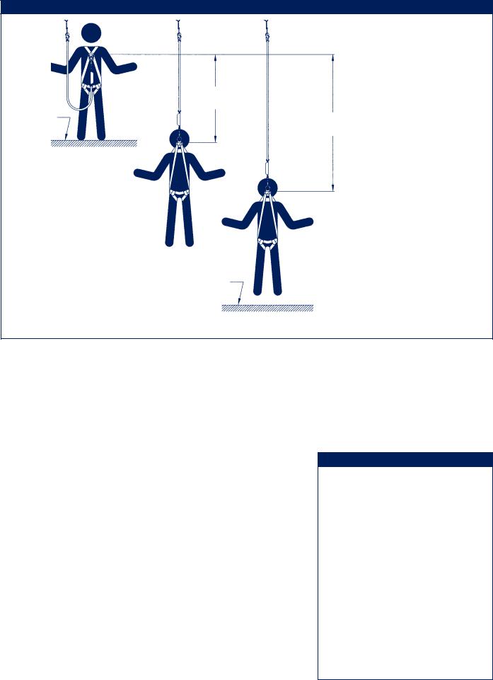
Figure 2 - Fall Clearance
|
6 Feet Max |
|
Free Fall |
Working Level |
Total Fall Distance |
|
(Free Fall + Deceleration Distance) |
Nearest Obstruction
C.FALL CLEARANCE: See Figure 2. There must be sufficient clearance below the user to arrest a fall before the user strikes the ground or other obstruction. The clearance required is dependent on the following factors:
• Elevation of anchorage connector |
• |
Connecting subsystem length |
|
• |
Deceleration distance |
• |
Movement of harness attachment element |
• |
Worker height |
• |
Free fall distance |
See personal fall arrest system manufacturer’s instructions for more information.
D.SWING FALLS: See Figure 3. Swing falls occur when the anchorage point is not directly above the point where a fall occurs. The force of striking an object in a swing fall may cause serious injury or death. Minimize swing falls by working as close to the anchorage point as possible. Do not permit
a swing fall if injury could occur. Swing falls will significantly increase the clearance required when a self retracting lifeline or other variable length connecting subsystem is used.
E.ENVIRONMENTAL HAZARDS: Use of this equipment in areas with environmental hazards may require additional precautions to prevent injury to the user or damage to the equipment. Hazards may include, but are not limited to; heat, chemicals, corrosive environments, high voltage power lines, gases, moving machinery, and sharp edges. Contact DBI-SALA if you have questions about using this equipment where environmental hazards exist.
F.TRAINING: This equipment must be installed and used by persons trained in its correct application and use. See section 4.0.
Figure 3 - Swing Falls
Swing Fall Hazard
3

1.3APPLICABLE STANDARDS: Refer to national standards, including ANSI Z359.1; and local, state, and federal requirements for more information on personal fall arrest systems and associated components.
2.0SYSTEM REQUIREMENTS
2.1COMPATIBILITY OF COMPONENTS: DBI-SALA equipment is designed for use with DBI-SALA approved
components and subsystems only. Substitutions or replacements made with non-approved components or subsystems may jeopardize compatibility of equipment and may effect the safety and reliability of the complete system.
2.2COMPATIBILITY OF CONNECTORS: Connectors are considered to be compatible with connecting elements when they have been designed to work together in such a way that their sizes and shapes do not cause their gate mechanisms to inadvertently open regardless of how they become oriented. Contact DBI-SALA if you have any questions about compatibility.
Connectors ( hooks, carabiners, and D-rings) must be capable of supporting at least 5,000 lbs. (22.2kN). Connectors must be compatible with the anchorage or other system components. Do not use equipment that is not compatible. Non-compatible connectors may unintentionally disengage. See Figure 4. Connectors must be compatible in size, shape, and strength. Self locking snap hooks and carabiners are required by ANSI Z359.1 and OSHA.
Figure 4 - Unintentional Disengagement (Roll-out)
If the connecting element that a snap hook (shown) or carabiner attaches to is undersized or irregular in shape, a situation could occur where the connecting element applies a force to the gate of the snap hook or carabiner. This force may cause the gate (of either a self-locking or a non-locking snap hook) to open, allowing the snap hook or carabiner to disengage from the connecting point.
Small ring or other non-compatibly shaped element
1. Force is applied to the snap hook.
2. The gate presses against the connecting ring.
3. The gate opens allowing the snap hook to slip off.
2.3MAKING CONNECTIONS: Only use self-locking snap hooks and carabiners with this equipment. Only use connectors that are suitable to each application. Ensure all connections are compatible in size, shape and strength. Do not use equipment that is not compatible. Ensure all connectors are fully closed and locked.
DBI-SALA connectors (snap hooks and carabiners) are designed to be used only as specified in each product’s user’s instructions. See Figure 5 for inappropriate connections. DBI-SALA snap hooks and carabiners should not be connected:
A. To a D-ring to which another connector is attached.
B. In a manner that would result in a load on the gate.
NOTE: Large throat opening snap hooks should not be connected to standard size D-rings or similar objects which will result in a load on the gate if the hook or D-ring twists or rotates. Large throat snap hooks are designed for use on fixed structural elements such as rebar or cross members that are not shaped in a way that can capture the gate of the hook.
4
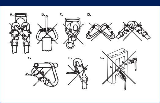
C. |
In a false |
Figure 5 - Inappropriate Connections |
|
engagement, |
|
|
where features |
|
|
that protrude |
|
|
from the snap |
|
|
hook or carabiner |
|
|
catch on the |
|
|
anchor and |
|
|
without visual |
|
|
confirmation |
|
|
seems to be fully |
|
|
engaged to the |
|
|
anchor point. |
|
D. |
To each other. |
|
E. |
Directly to |
|
|
webbing or rope |
|
|
lanyard or tie- |
|
|
back (unless the |
|
|
manufacturer’s |
|
|
instructions for |
|
|
both the lanyard |
|
|
and connector |
|
|
specifically allows |
|
|
such a connection). |
|
F.To any object which is shaped or dimensioned such that the snap hook or carabiner will not close and lock, or that roll-out could occur.
G.In a manner that does not allow the connector to align properly while under load.
2.4PERSONAL FALL ARREST SYSTEM: Personal fall arrest systems used with this equipment must meet applicable state, federal, OSHA, and ANSI requirements. A full body harness must be worn when this equipment is used as a component of a personal fall arrest system. As required by OSHA, the personal fall arrest system must be capable of arresting the user’s fall with a maximum arresting force of 1,800 lbs., and limit the free fall to 6 feet or less. If the maximum free fall distance must be exceeded, the employer must document, based on test data, that the maximum arresting force will not be exceeded, and the personal fall arrest system will function properly.
When a free fall greater than 6 feet, and up to a maximum of 12 feet is possible, DBI-SALA recommends using a personal fall arrest system incorporating a DBI-SALA Force2 Energy Absorbing Lanyard. DBI-SALA has performed testing using the Force2 Energy Absorbing Lanyard in free falls up to 12 feet to ensure the maximum arresting force does not exceed 1,800 lbs., and the system functions properly. The results of these tests are listed in the user instruction manual provided with Force2 Energy Absorbing Lanyards.
2.5ANCHORAGE STRUCTURE: This equipment is intended to be installed on structures capable of meeting the anchorage strength requirements specified below. The anchorage connector must be of sufficient length to wrap completely around the anchorage.
2.6ANCHORAGE STRENGTH: The anchorage strength required is dependent on the application. Following are anchorage strength requirements for specific applications:
A.FALL ARREST: The structure to which the anchorage connector is attached must sustain static loads applied in the directions permitted by the fall arrest system of at least: 3,600 lbs. with certification of a qualified person, or 5,000 lbs. without certification. See ANSI Z359.1 for certification definition. When more than one personal fall arrest system is attached to an anchorage, the strengths stated above must be multiplied by the number of personal fall arrest systems attached to the anchorage.
From OSHA 1926.500 and 1910.66: Anchorages used for attachment of a personal fall arrest system shall be independent of any anchorage being used to support or suspend platforms, and must support at least 5,000 lbs. per user attached; or be designed, installed, and used as part of a complete personal fall arrest system which maintains a safety factor of at least two, and is supervised by a qualified person.
5
 Loading...