

Page 1
Instructions for the following series products:
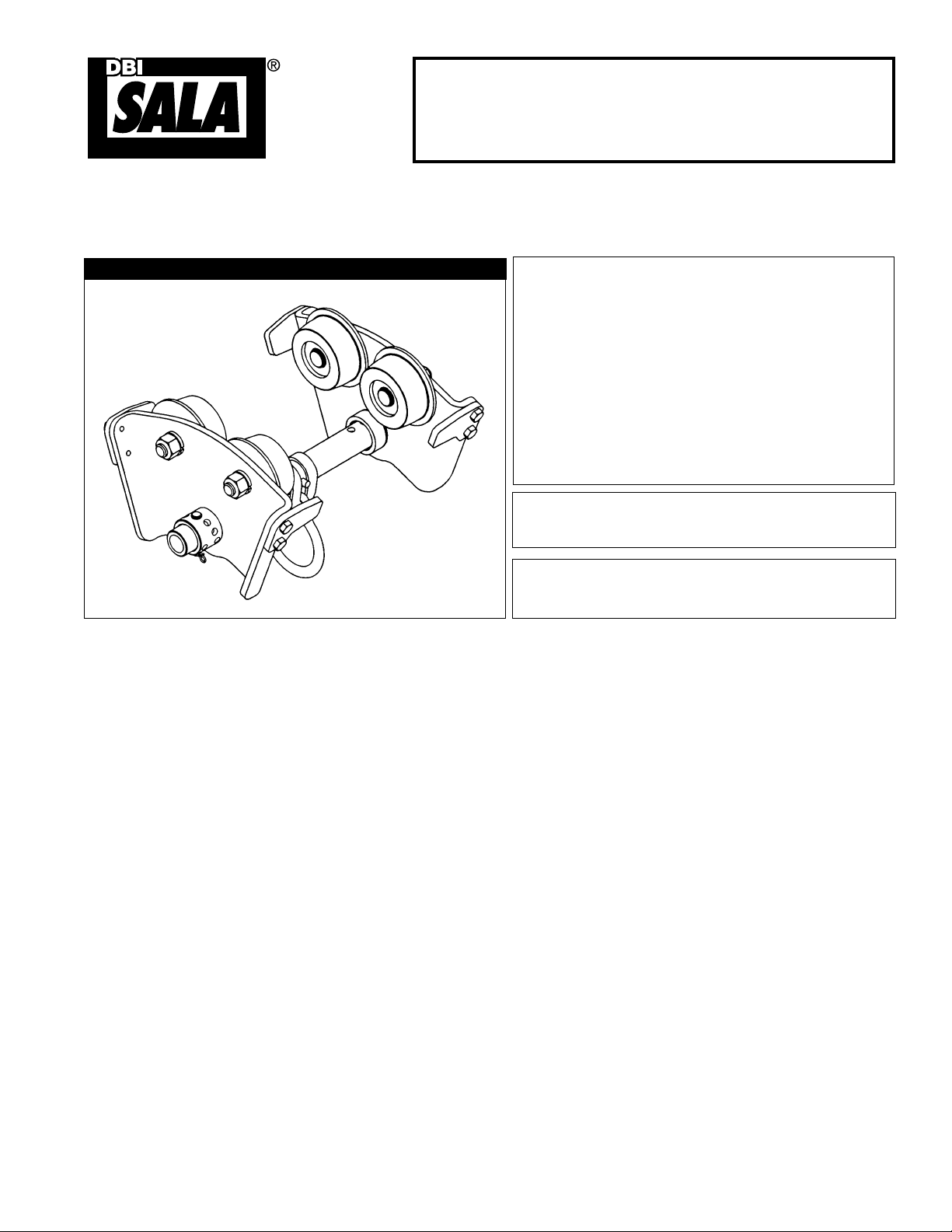
Beam Trolley Anchorage
(Model Numbers: 2103143, 2103147, 2103149)
The Ultimate in Fall Protection
USER INSTRUCTION MANUAL TROLLEY ANCHORAGE CONNECTOR
This manual is intended to meet the Manufacturer’s Instructions as required by ANSI-Z359.1 and should be used
as part of an employee training program as required by OSHA.
Figure 1 - Trolley Anchorage Connector
WARNING: This product is part of a personal
restraint, work positioning, suspension, or rescue
system. These instructions must be provided to the
user and rescuer (see section 8.0 Terminology). The
user must read and understand these instructions
or have them explained to them before using this
equipment. The user must read and follow the
manufacturer’s instructions for each component
or part of the complete system. Manufacturer’s
instructions must be followed for proper use and
maintenance of this product. Alterations or misuse
of this product or failure to follow instructions may
result in serious injury or death.
IMPORTANT: If you have questions on the use, care,
or suitability of this equipment for your application,
contact DBI-SALA.
IMPORTANT: Record the product identifi cation
information from the ID label in the inspection and
maintenance log in section 10.0 of this manual.
1.0 APPLICATIONS
1.1 PURPOSE: The Trolley Anchorage Connector is designed to move along horizontal beams with an attached
personal fall arrest system. This trolley is to be used only as a component of a personal fall arrest system.
Do not hang, lift, or support tools or equipment from the trolley.
A. FALL ARREST: The trolley is used as a component of a personal fall arrest system. Personal fall arrest
systems typically include a self retracting lifeline, connector to attach the self retracting lifeline to the
trolley, and full body harness. A personal fall arrest system is used where a free fall is possible before
the fall is arrested.
1.2 LIMITATIONS: Consider the following application limitations before using this equipment:
A. BEAMS: The trolley may be used on beam flanges 3 in. (7.6 cm) to 8 in. ( 20.3 cm) wide and up to 11/16 in.
(1.75 cm) thick. The minimum radius the trolley can follow is 48 in. (122 cm). The beam structure must meet
the strength requirements specified in section 2.4. The beam must be horizontal and level.
B. CAPACITY: The trolley is designed for use by persons with a combined weight (clothing, tools, etc.) of no
more than 310 lbs (141 kg). Only one personal fall arrest system may be connected to a single trolley.
C. PERSONAL FALL ARREST SYSTEM: Personal fall arrest systems used with the trolley must meet the
system requirements as specified in section 2.5.
D. FREE FALL: Personal fall arrest systems used with the trolley must be rigged to limit the free fall to
6 feet. See subsystem manufacturer’s instructions for more information.
E. FALL CLEARANCE: There must be sufficient clearance below the user to arrest a fall before the user
strikes the ground or other obstruction. The clearance required is dependent on the following factors:
• Elevation of Trolley • Connecting subsystem length
• Deceleration distance • Movement of harness attachment element
• Worker height • Free fall distance
See personal fall arrest system manufacturer’s instructions for more information.
Form: 5902145
Rev: G
© Copyright 2014, Capital Safety
Page 2
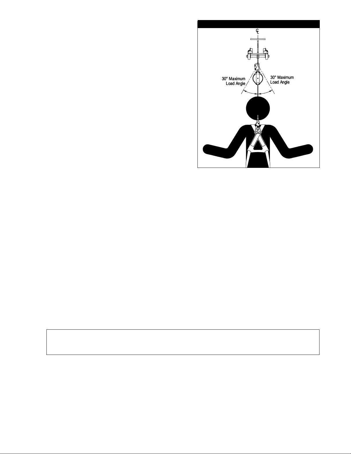
F. TROLLEY LOAD ANGLE: Loads imposed on the trolley
Figure 2 - Trolley Load Angle
by the personal fall arrest system must remain within
30 degrees of the vertical center line of the beam. See
Figure 2.
G. ENVIRONMENTAL HAZARDS: Use of this equipment
in hazardous environments may require additional
precautions to reduce the possibility of injury to the user
or damage to the equipment. Hazards may include, but
are not limited to; heat, extreme cold, caustic chemicals,
corrosive environments, high voltage power lines,
explosive or toxic gases, moving machinery, and sharp
edges.
H. TRAINING: This equipment is intended to be installed
and used by persons trained in its application and use.
1.3 APPLICABLE STANDARDS: Refer to applicable local, state,
and federal (OSHA) requirements governing this equipment
for more information on anchorage connectors and
associated system components, including OSHA 1910.66,
appendix C and OSHA1926.502.
2.0 SYSTEM REQUIREMENTS
2.1 COMPATIBILITY OF COMPONENTS: DBI-SALA equipment is designed for use with DBI-SALA approved
components and subsystems only. Substitutions or replacements made with non-approved components
or subsystems may jeopardize compatibility of equipment and may affect the safety and reliability of the
complete system.
2.2 COMPATIBILITY OF CONNECTORS: Connectors are considered to be compatible with connecting
elements when they have been designed to work together in such a way that their sizes and shapes do
not cause their gate mechanisms to inadvertently open regardless of how they become oriented. Contact
DBI-SALA if you have any questions about compatibility.
Connectors (hooks, carabiners, and D-rings) must be capable of supporting at least 5,000 lbs. (22.2kN).
Connectors must be compatible with the anchorage or other system components. Do not use equipment
that is not compatible. Non-compatible connectors may unintentionally disengage. See Figure 3. Connectors
must be compatible in size, shape, and strength. Self locking snap hooks and carabiners are required by
ANSI Z359.1 and OSHA, and in Canada, by CSA Z259.12.
2.3 MAKING CONNECTIONS: Only use self-locking snap hooks and carabiners with this equipment. Only use
connectors that are suitable to each application. Ensure all connections are compatible in size, shape and
strength. Do not use equipment that is not compatible. Ensure all connectors are fully closed and locked.
DBI-SALA connectors (snap hooks and carabiners) are designed to be used only as specifi ed in each
product’s user’s instructions. See Figure 4 for inappropriate connections. DBI-SALA snap hooks and
carabiners should not be connected:
A. To a D-ring to which another connector is attached.
B. In a manner that would result in a load on the gate.
NOTE: Large throat snap
in a load on the gate if the hook or D-ring twists or rotates. Large throat snap
structural elements such
hook.
hooks should not be connected
as rebar or cross members that are not shaped in a way that can capture the gate of the
to standard size D-rings or similar objects which will result
hooks are designed for use on fi xed
C. In a false engagement, where features that protrude from the snap hook or carabiner catch on the
anchor and without visual confirmation seems to be fully engaged to the anchor point.
D. To each other.
E. Directly to webbing or rope lanyard or tie-back (unless the manufacturer’s instructions for both the
lanyard and connector specifically allow such a connection).
F. To any object which is shaped or dimensioned such that the snap hook or carabiner will not close and
lock, or that roll-out could occur.
G. In a manner that does not allow the connector to align properly while under load.
2
Page 3
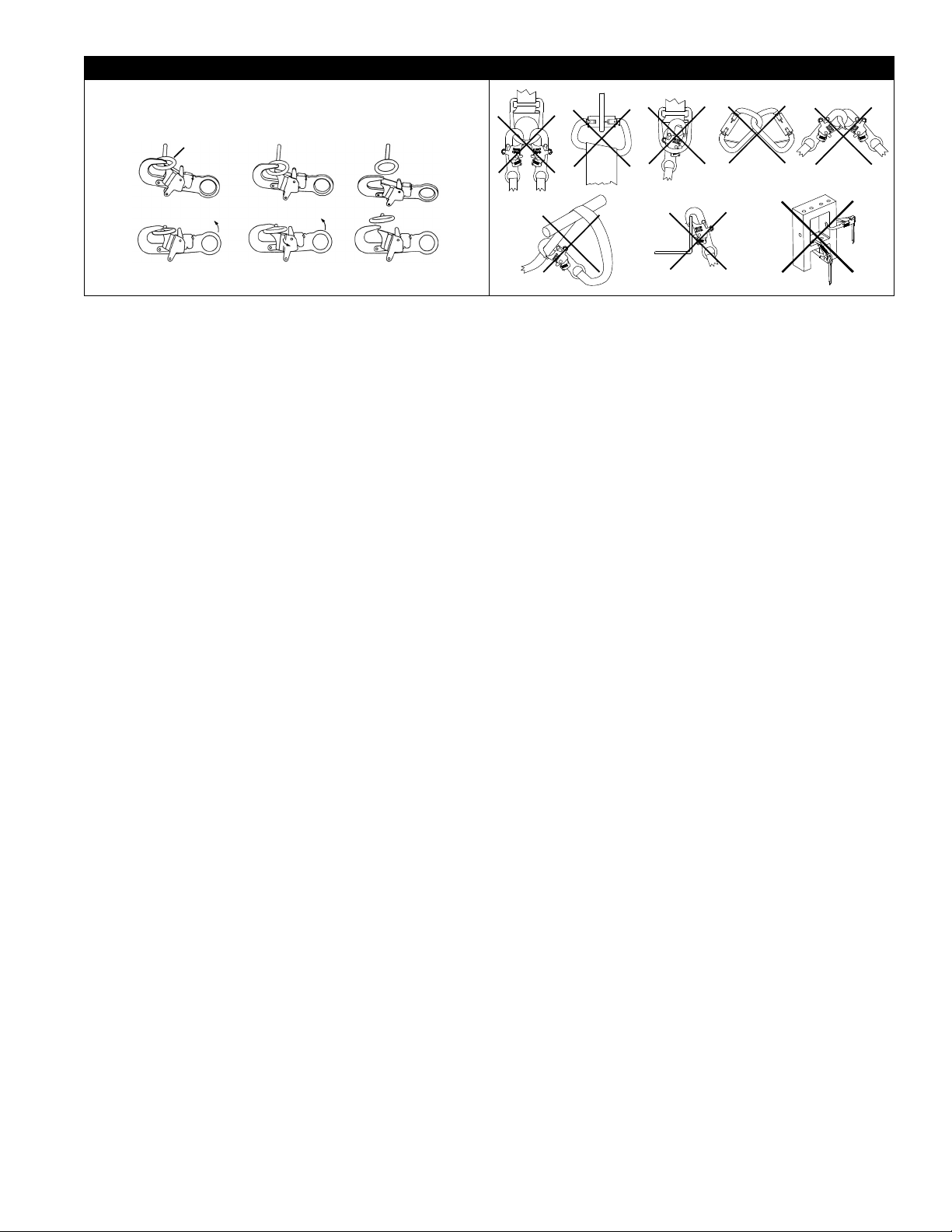
Figure 3 - Unintentional Disengagement Figure 4 - Inappropriate Connections
If the connecting element to which a snap hook (shown) or carabiner attaches
is undersized or irregular in shape, a situation could occur where the connecting
element applies a force to the gate of the snap hook or carabiner. This force may
cause the gate (of either a self-locking or a non-locking snap hook) to open,
allowing the snap hook or carabiner to disengage from the connecting point.
Small ring or other
non-compatibly
shaped element
A. B. C. D.
E. F. G.
Force is applied to the
Snap Hook.
The Gate presses against
the Connecting Ring.
The Gate opens allowing
the Snap Hook to slip off.
2.4 ANCHORAGE STRUCTURE STRENGTH: The structure to which the trolley is installed must sustain static
loads in the directions permitted by the personal fall arrest system of at least 5,000 lbs. (22.2 kN) When
more than one trolley is installed on the same anchorage structure, the anchorage structure strength must
be multiplied by the number of personal fall arrest systems attached to the structure.
From OSHA 1926.500 and 1910.66: Anchorages used for attachment of a personal fall arrest system shall
be independent of any anchorage being used to support or suspend platforms, and must support at least
5,000 lbs. (22.2 kN) per user attached; or be designed, installed, and used as part of a complete personal
fall arrest system which maintains a safety factor of at least two, and is supervised by a qualifi ed person.
2.5 PERSONAL FALL ARREST SYSTEM: Personal fall arrest systems used with this equipment must meet
applicable local, state, and federal (OSHA) requirements. A personal fall arrest system incorporating a full
body harness must be capable of arresting a user’s fall with a maximum arresting force of 1,800 lbs. (816
kg), and limit the free fall distance to 6 ft. (1.8 m) or less. The deceleration distance must be 42 in. (107
cm) or less.
3
Page 4
3.0 INSTALLATION AND USE
WARNING: Do not alter or intentionally misuse this equipment.
Consult with DBI-SALA if using this equipment with components
or subsystems other than those described in this manual. Some
subsystem and component combinations may interfere with the
operation of this equipment.
WARNING: Consult with your doctor if there is any reason to
doubt your fi tness to safely absorb the shock from a fall arrest.
Age and fi tness can seriously affect your ability to withstand falls.
Pregnant women and minors must not use this equipment.
3.1 BEFORE EACH USE of this equipment inspect it
according to section 5.0.
3.2 PLAN your fall arrest system before installing and
using this equipment. Consider all factors affecting
your safety during use. The following list gives some
important points to consider when planning your system:
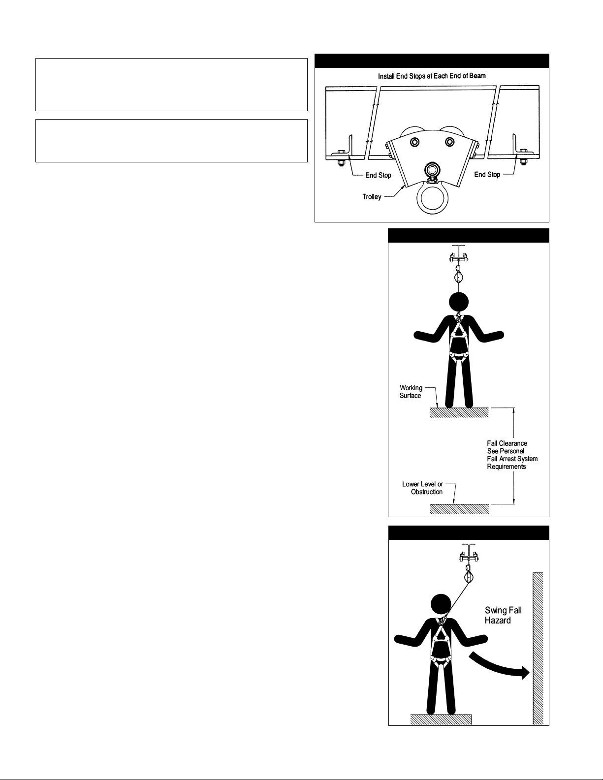
A. ANCHORAGE BEAM: Select a rigid anchorage beam that is capable
of supporting the loads specified in section 2.4. Joints between
beam sections must be flush to allow the trolley to pass over
smoothly. The beam must have end stops at each end to prevent
the trolley from rolling off the beam. The end stops must be sized
and positioned to safely stop the trolley. The trolley should not
catch or hang-up on the end stop; the trolley must be able to freely
return in the opposite direction after contacting the end stop. See
Figure 5.
Figure 5 - End Stops
Figure 6 - Fall Clearance
B. FALL CLEARANCE: See Figure 6. There must be sufficient
clearance in your fall path to prevent striking an object or lower
level in the event of a fall. The amount of clearance required is
dependent on the application. See personal fall arrest system
manufacturer’s instructions for information on calculating fall
clearance.
C. SWING FALLS: See Figure 7. Swing falls occur when the
anchorage point is not directly overhead. The force of striking an
object in a swing fall may cause serious injury or death. Minimize
swing falls by working as directly below the anchorage point as
possible. Do not permit a swing fall if injury could occur. Swing
falls will significantly increase the clearance required when a self
retracting lifeline or other variable length connecting subsystem
is used. If a swing fall situation exists in your application contact
DBI-SALA before proceeding.
D. SHARP EDGES: Avoid working where parts of the system will be in
contact with, or abrade against, unprotected sharp edges.
E. AFTER A FALL: Any equipment which has been subjected to
the forces of arresting a fall or exhibits damage consistent with
the effect of fall arrest forces as described in section 5, must be
removed from service immediately and destroyed by the user, the
rescuer, or an authorized person.
F. RESCUE: When using this equipment, the employer must
have a rescue plan and the means at hand to implement it and
communicate that plan to users, authorized persons, and rescuers.
Figure 7 - Swing Falls
3.3 INSTALLATION:
ATTACHING TROLLEY TO BEAM:
Step 1. Measure the beam fl ange width to determine the adjustment
hole settings on the trolley. Figure 8 shows the hole positions
on the left and right adjuster dials and load bar that correspond
with Table 1. See Table 1 for the adjustment hole settings for
your beam fl ange width.
4
Page 5

Step 2. To open one side of the trolley, remove the clip or cotter pin from the clevis pin and pull clevis pin
out of adjuster dial. Pull the side plate with wheels and adjuster dial off the load bar.
Step 3. On the assembled side of the trolley, adjust the width to the required settings from Table 1 by
installing the clevis pin vertically, with the clevis pin head on top (see Figure 8), through the
appropriate adjuster dial and load bar holes.
Step 4. Place the partially assembled trolley onto the bottom fl ange of the beam with the D-ring hanging
down. Slide the un-assembled side plate onto the load bar and align with the required adjuster
dial and load bar holes. Install a clevis pin vertically, with the clevis pin head on top (see Figure 8),
through the adjuster dial and load bar holes.
• If the beam fl ange is too wide to install the clevis pin through the correct holes, adjust the
trolley to the next larger beam fl ange size as specifi ed in Table 1.
• The distance from the trolley wheel face to the edge of the beam fl ange must be no more than
1/16 in. (0.16 cm). If the distance is greater than 1/16 in. (0.16 cm), adjust the trolley to the
next smaller beam fl ange size as specifi ed in Table 1.
Step 5. Install the clip or cotter pins through the clevis pins and secure them by bending back the cotter pin
legs.
WARNING: Trolley width settings specifi ed in Table 1 must be followed. Adjustments on the load bar must use the
same setting on both sides (i.e. A - A, B - B, etc.). Adjustments on the adjuster dial must be within one unit. Failure to
use correct settings may improperly load the trolley.
IMPORTANT: If the trolley is moved to another beam, or if the cotter pins are removed, cotter pins must be replaced.
Use 5/64 x 3/4”, 18-8 stainless steel cotter pins or Pivot Point bow-tie™ clip cotter pins (bow 72). If you are using Pivot
Point bow-tie™ clips, they are reusable.
3.4 ATTACHING PERSONAL FALL ARREST SYSTEM TO TROLLEY: Attach your personal fall arrest system
to the anchorage point indicated in Figure 8. When using a hook or carabiner to connect to the anchorage,
ensure roll-out cannot occur. Roll-out occurs when interference between the hook and mating connector
causes the hook gate to unintentionally open and release. Self locking snap hooks and carabiners should
be used to reduce the possibility of roll-out. Do not use hooks or connectors that will not completely close
over the attachment object. Do not connect snap hooks or carabiners to each other. See personal fall arrest
system manufacturer’s instructions for connecting subsystems used with the trolley.
4.0 TRAINING
4.1 The user and purchaser of this equipment must be familiar with the instructions, operating characteristics,
application limits, and the consequences of improper use of this equipment. Users and purchasers must be
trained in the correct care and use of this equipment.
WARNING: Training must be conducted without exposing the trainee to a fall hazard. Training should be repeated on a
periodic basis.
5.0 INSPECTION
5.1 FREQUENCY:
• BEFORE EACH USE: Inspect trolley according to sections 5.2 and 5.3.
• ANNUALLY: The trolley must be inspected by a competent person other than the user. See sections 5.2
and 5.3 for inspection guidelines.
5.2 INSPECTION STEPS:
Step 1. Inspect trolley for damage. Look for cracks or deformities. Look for excessive wear or damage to the
anchorage point. All fasteners must be secure.
Step 2. Inspect trolley wheels. All wheels should turn freely and be undamaged.
Step 3. Inspect entire unit for corrosion.
Step 4. The warning label must be present and fully legible. See section 9.0.
Step 5. Record inspection results in section 10.0.
WARNING: If this equipment is subjected to the forces of a fall arrest, it must be removed from service and
destroyed, or returned to DBI-SALA for inspection and repair.
5.3 If inspection reveals an unsafe or defective condition remove from service and destroy or contact DBI-SALA
for repair.
5
Page 6

Figure 8 - Attaching Trolley To Beam - Anchorage Point
Beam Flange
Wheel Face
1/16” (0.16 cm)
Wheel Face to Edge
of Beam Flange
Right Adjuster Dial
Left Adjuster Dial
Left Adjuster Dial
Adjuster Detail
Hole Positions
Load Bar
See Load Bar Detail
for hole positions.
Side Plate
Adjuster Dial
See Adjuster Dial Detail
for hole positions.
Right Adjuster Dial
Load Bar Detail
Hole Positions
Clevis Pin
Install vertically
with head up
Bow-Tie Pin
or
Cotter Pin
Side Plate
w/Wheels
Anchorage Point
6
Page 7

Table 1 - Trolley Width Adjustment
Beam Flange Width (in inches)
From
3 3 1/8 D 1 1
3 1/8 3 1/4 D 1 2
3 1/4 3 3/8 D 2 2
3 3/8 3 1/2 D 2 3
3 1/2 3 5/8 D 3 3
3 5/8 3 3/4 D 3 4
3 3/4 3 7/8 D 4 4
3 7/8 4 D 4 5
4 4 1/8 D 5 5
4 1/8 4 1/4 D 5 6
4 1/4 4 3/8 C 1 1
4 3/8 4 1/2 C 1 2
4 1/2 4 5/8 C 2 2
4 5/8 4 3/4 C 2 3
4 3/4 4 7/8 C 3 3
4 7/8 5 C 3 4
5 5 1/8 C 4 4
5 1/8 5 1/4 C 4 5
5 1/4 5 3/8 C 5 5
5 3/8 5 1/2 C 5 6
5 1/2 5 5/8 B 1 1
5 5/8 5 3/4 B 1 2
5 3/4 5 7/8 B 2 2
5 7/8 6 B 2 3
6 6 1/8 B 3 3
6 1/8 6 1/4 B 3 4
6 1/4 6 3/8 B 4 4
6 3/8 6 1/2 B 4 5
6 1/2 6 5/8 B 5 5
6 5/8 6 3/4 B 5 6
6 3/4 6 7/8 A 1 1
6 7/8 7 A 1 2
7 7 1/8 A 2 2
7 1/8 7 1/4 A 2 3
7 1/4 7 3/8 A 3 3
7 3/8 7 1/2 A 3 4
7 1/2 7 5/8 A 4 4
7 5/8 7 3/4 A 4 5
7 3/4 7 7/8 A 5 5
7 7/8 8 A 5 6
8 --- A 6 6
Up to, but not
including
Load Bar Holes
(Both Sides)
Left Adjuster
Dial Hole
Right Adjuster
Dial Hole
7
Page 8

6.0 MAINTENANCE, SERVICING, STORAGE
6.1 MAINTENANCE: Clean the trolley using water and mild detergent. Wipe dry with a clean cloth and hang
to air dry. Do not force dry with heat. An excessive build-up of dirt, paint, etc. may prevent the trolley from
working correctly. No lubrication is required.
6.2 SERVICING: Servicing must be completed by an authorized service center. Authorization must be in
writing.
6.3 STORAGE: Store this equipment in a cool, dry, clean environment. Inspect the trolley after extended
storage.
7.0 SPECIFICATIONS
7.1 MATERIALS:
2103143
TROLLEY: Steel Frame, shielded wheel bearings
LOAD BAR: Alloy steel
D-RING: Alloy steel
PIVOT POINT BOW-TIE™ CLIP COTTER PIN: bow 72
2103147
TROLLEY: 304 stainless steel frame
LOAD BAR: 303 stainless steel
BEARINGS: 440 stainless steel
WHEELS: 303 stainless steel
ADJUSTERS: 303 stainless steel
D-RING: Forged 304 stainless steel
FASTENERS: 18-8 stainless steel
COTTER PINS: 5/64 in. x 3/4 in., 18-8 stainless steel
8
Page 9

7.2 DIMENSIONS (IN INCHES):
8.81 in.
(22.38 cm)
11.63 in.
(29.54 cm)
8.42 in.
(21.39 cm)
8.0 TERMINOLOGY
AUTHORIZED PERSON: A person assigned by the employer to perform duties at a location where the person
will be exposed to a fall hazard (otherwise referred to as “user” for the purpose of these instructions).
RESCUER: Person or persons other than the rescue subject acting to perform an assisted rescue by
operation of a rescue system.
CERTIFIED ANCHORAGE: An anchorage for fall arrest, positioning, restraint, or rescue systems that a
qualified person certifies to be capable of supporting the potential fall forces that could be encountered
during a fall or that meet the criteria for a certified anchorage prescribed in this standard.
QUALIFIED PERSON: A person with a recognized degree or professional certificate and with extensive
knowledge, training, and experience in the fall protection and rescue field who is capable of designing,
analyzing, evaluating and specifying fall protection and rescue systems to the extent required by this
standard.
COMPETENT PERSON: One who is capable of identifying existing and predictable hazards in the surroundings
or working conditions which are unsanitary, hazardous, or dangerous to employees, and who has
authorization to take prompt corrective measures to eliminate them.
5.66 in.
(14.38 cm)
9
Page 10

9.0 LABELING
9.1 This label must be present and fully legible:
10
Page 11

INSPECTION AND MAINTENANCE LOG
SERIAL NUMBER:
MODEL NUMBER:
DATE PURCHASED: DATE OF FIRST USE:
INSPECTION DATE INSPECTION ITEMS
NOTED
Approved By:
Approved By:
Approved By:
Approved By:
Approved By:
Approved By:
Approved By:
Approved By:
CORRECTIVE ACTION MAINTENANCE
PERFORMED
Approved By:
Approved By:
Approved By:
Approved By:
Approved By:
Approved By:
Approved By:
Approved By:
Approved By:
Approved By:
Page 12

LIMITED LIFETIME WARRANTY
Warranty to End User: D B Industries, Inc., dba CAPITAL SAFETY USA (“CAPITAL SAFETY”) warrants to the
original end user (“End User”) that its products are free from defects in materials and workmanship under
normal use and service. This warranty extends for the lifetime of the product from the date the product is
purchased by the End User, in new and unused condition, from a CAPITAL SAFETY authorized distributor.
CAPITAL SAFETY’S entire liability to End User and End User’s exclusive remedy under this warranty is limited
to the repair or replacement in kind of any defective product within its lifetime (as CAPITAL SAFETY in its sole
discretion determines and deems appropriate). No oral or written information or advice given by CAPITAL
SAFETY, its distributors, directors, offi cers, agents or employees shall create any different or additional
warranties or in any way increase the scope of this warranty. CAPITAL SAFETY will not accept liability for defects
that are the result of product abuse, misuse, alteration or modifi cation, or for defects that are due to a failure to
install, maintain, or use the product in accordance with the manufacturer’s instructions.
CAPITAL SAFETY’S WARRANTY APPLIES ONLY TO THE END USER. THIS WARRANTY IS THE ONLY WARRANTY
APPLICABLE TO OUR PRODUCTS AND IS IN LIEU OF ALL OTHER WARRANTIES AND LIABILITIES, EXPRESSED
OR IMPLIED. CAPITAL SAFETY EXPRESSLY EXCLUDES AND DISCLAIMS ANY IMPLIED WARRANTIES OF
MERCHANTABILITY OR FITNESS FOR A PARTICULAR PURPOSE, AND SHALL NOT BE LIABLE FOR INCIDENTAL,
PUNITIVE OR CONSEQUENTIAL DAMAGES OF ANY NATURE, INCLUDING WITHOUT LIMITATION, LOST PROFITS,
REVENUES, OR PRODUCTIVITY, OR FOR BODILY INJURY OR DEATH OR LOSS OR DAMAGE TO PROPERTY, UNDER
ANY THEORY OF LIABILITY, INCLUDING WITHOUT LIMITATION, CONTRACT, WARRANTY, STRICT LIABILITY, TORT
(INCLUDING NEGLIGENCE) OR OTHER LEGAL OR EQUITABLE THEORY.
CSG USA & Latin America
3833 SALA Way
Red Wing, MN 55066-5005
Toll Free: 800.328.6146
Phone: 651.388.8282
Fax: 651.388.5065
solutions@capitalsafety.com
CSG EMEA
(Europe, Middle East, Africa)
Le Broc Center
Z.I. 1ère Avenue
5600 M B.P. 15 06511
Carros
Le Broc Cedex
France
Phone: + 33 4 97 10 00 10
Fax: + 33 4 93 08 79 70
information@capitalsafety.com
The Ultimate in Fall Protection
CSG Canada
260 Export Boulevard
Mississauga, ON L5S 1Y9
Phone: 905.795.9333
Toll-Free: 800.387.7484
Fax: 888.387.7484
info.ca@capitalsafety.com
CSG Australia & New Zealand
95 Derby Street
Silverwater
Sydney NSW 2128
AUSTRALIA
Phone: +(61) 2 8753 7600
Toll-Free : 1 800 245 002 (AUS)
Toll-Free : 0800 212 505 (NZ)
Fax: +(61) 2 87853 7603
sales@capitalsafety.com.au
www.capitalsafety.com
ISO
9001
CSG Northern Europe
5a Merse Road
North Moons, Moat
Reditch, Worcestershire, UK
B98 9HL
Phone: + 44 (0)1527 548 000
Fax: + 44 (0)1527 591 000
csgne@capitalsafety.com
CSG Asia
Singapore:
16S, Enterprise Road
Singapore 627666
Phone: +65 - 65587758
Fax: +65 - 65587058
inquiry@capitalsafety.com
Shanghai:
Rm 1406, China Venturetech Plaza
819 Nan Jing Xi Rd,
Shanghai 200041, P R China
Phone: +86 21 62539050
Fax: +86 21 62539060
 Loading...