

Page 1
The Ultimate in Fall Protection
This manual is intended to meet the Manufacturer’s Instructions as required by ANSI Z359.1
and should be used as part of an employee training program as required by OSHA.
User Instruction Manual
D-Ring Anchorage Connector
Models: 2101630, 2101632, 2101633, 2101634,
2101636, 2101638, 2109870
WARNING: This product is part of a personal fall arrest, restraint,
work positioning, personnel riding, or rescue system. The user must
follow the manufacturer’s instructions for each component of the
system. These instructions must be provided to the user of this
equipment. The user must read and understand these instructions
before using this equipment. Manufacturer’s instructions must
be followed for proper use and maintenance of this equipment.
Alterations or misuse of this equipment, or failure to follow these
instructions, may result in serious injury or death.
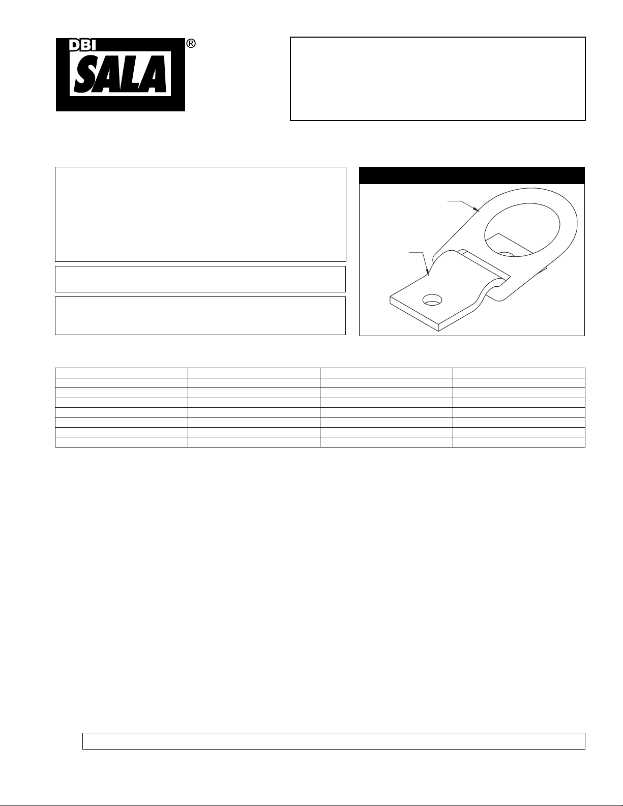
Figure 1 - D-Ring Anchorage Connector
D-Ring
Anchorage
Plate
IMPORTANT: If you have questions on the use, care, or
suitability of this equipment for your application, contact DBI-SALA.
IMPORTANT: Record the product identifi cation information
from the ID label in the “Inspection and Maintenance Log” at
the back of this manual
DESCRIPTION
Model D-Ring Anchorage Plate Mounting Hole Dia.
2101630 Forged Steel Stainless Steel 9/16 in (1.4 cm)
2101632 Forged Steel Forged Steel, Painted Black 9/16 in (1.4 cm)
2101633 Forged Steel Stainless Steel 9/16 in (1.4 cm)
2101634 Forged Steel Forged Steel 9/16 in (1.4 cm)
2101636 Stainless Steel Stainless Steel 9/16 in (1.4 cm)
2101638 Stainless Steel Stainless Steel 9/16 in (1.4 cm) / Weld On
2109870 Stainless Steel Stainless Steel Welld On (no holes)
1.0 APPLICATIONS
1.1 PURPOSE: The D-ring Anchorage Connector is designed for use as an attachment of a personal fall arrest,
restraint, work positioning, personnel riding, or rescue system to an anchorage. See Figure 2 for application
illustrations.
A. PERSONAL FALL ARREST: The D-ring Anchorage Connector is used as a component of a personal fall
arrest system to protect the user in the event of a fall. Personal fall arrest systems typically include a
full body harness and a connecting subsystem (energy absorbing lanyard). Maximum permissible free
fall is 6 feet (1.8 m) .
B. RESTRAINT: The D-ring Anchorage Connector is used as a component of a restraint system to prevent
the user from reaching a fall hazard. Restraint systems typically include a full body harness and a
lanyard or restraint line. No vertical free fall is permitted.
C. WORK POSITIONING: The D-ring Anchorage Connector is used as a component of a work positioning
system to support the user at a work position. Work positioning systems typically include a full body
harness, positioning lanyard, and a back-up personal fall arrest system. Maximum permissible free fall is
2 feet.
D. PERSONNEL RIDING: The D-ring Anchorage Connector is used as a component of a personnel riding
system to suspend or transport the user vertically. Personnel riding systems typically include a full body
harness, boatswains’s chair or seat board, and a back-up personal fall arrest system. No vertical free fall
is permitted.
E. RESCUE: The D-ring Anchorage Connector is used as a component of a rescue system. Rescue systems
are
confi gured depending on the type of rescue. No vertical free fall is permitted.
WARNING: Do not use the D-ring Anchorage Connector for applications not addressed in this manual.
Form No: 5902134 Rev: J © Copyright 2013, Capital Safety
Page 2
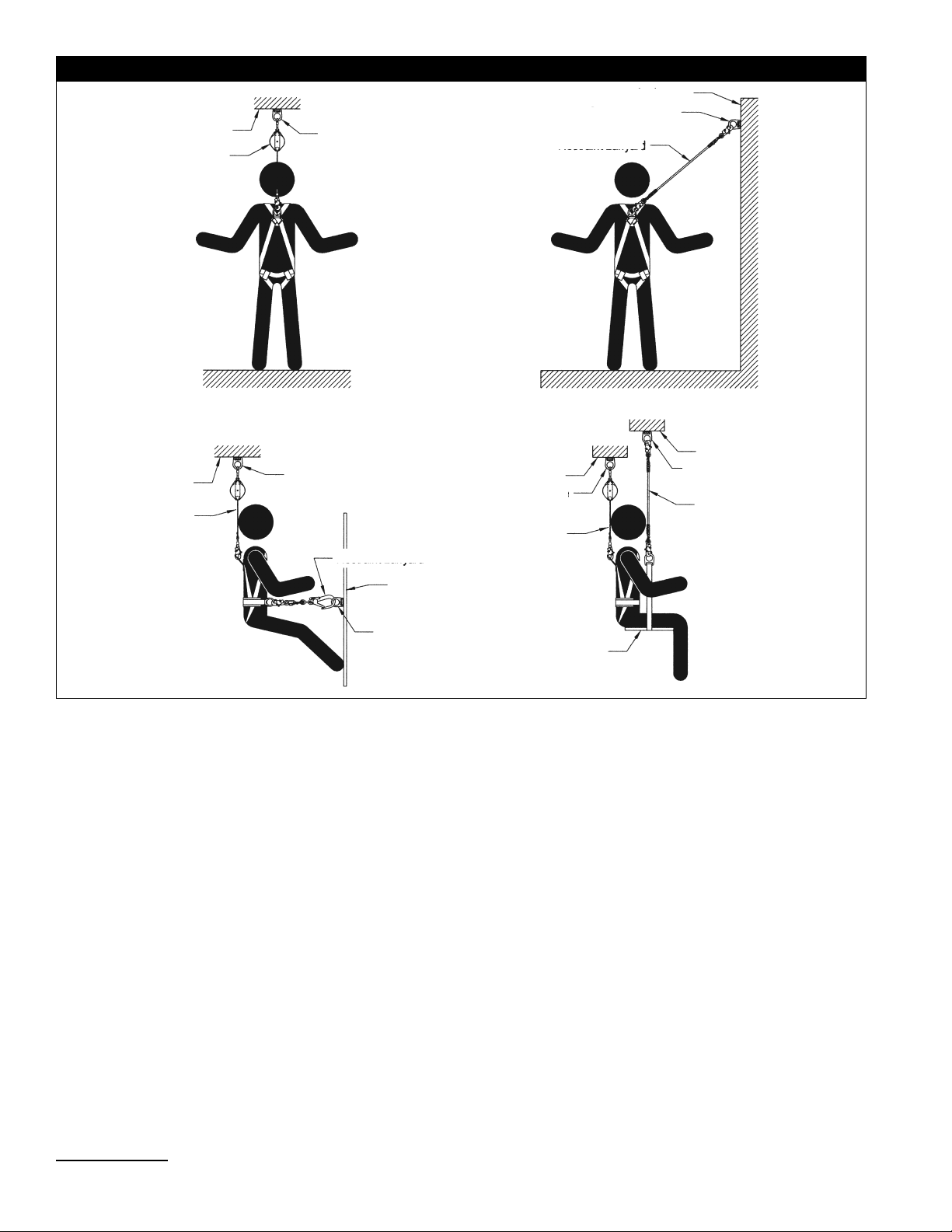
Anchorage
SRL
Figure 2 - Applications
D-Ring Anchorage
Connector
Anchorage
D-Ring Anchorage
Connector
Restraint Lanyard
Fall Arrest
Anchorage
Backup
Fall Arrest
System
Work Positioning
D-Ring Anchorage
Connector
Restraint Lanyard
D-Ring Anchorage
Connector
D-Ring Anchorage
Anchorage
Restraint
Anchorage
Connector
Backup
Fall Arrest
System
Seat
Board
Personnel Ridingl
Anchorage
D-Ring Anchorage
Connector
Suspension
Line
1.2 LIMITATIONS: Consider the following application limitations before using this equipment:
A. CAPACITY: The D-ring Anchorage Connector is designed for use by persons with a combined weight
(clothing, tools, etc.) of no more than 310 lbs (141 kg)1. No more than one personal protective system
may be connected at one time. Note: For emergency rescues it may be acceptable to connect
more than one system if the anchorage will support the anticipated loads.
B. FREE FALL: Personal fall arrest systems used with this equipment must be rigged to limit the free fall
to 6 feet (1.8 m) per ANSI Z359.1. See the personal fall arrest system manufacturer’s instructions
for more information. Restraint systems must be rigged so that no vertical free fall is possible. Work
positioning systems must be rigged so that free fall is limited to 2 feet (0.6 m) or less. Personnel riding
systems must be rigged so that no vertical free fall is possible. Rescue systems must be rigged so that
no vertical free fall is possible.
C. FALL CLEARANCE: There must be sufficient clearance below the user to arrest a fall before the user
strikes the ground or other obstruction. The clearance required is dependent on the following factors:
• Deceleration Distance • Movement of Attachment Element
• Free Fall Distance • Elevation of Anchorage Connector
• Worker Height • Connection Subsystem Length
See the Personal Fall Arrest System manufacturer’s instructions for more information.
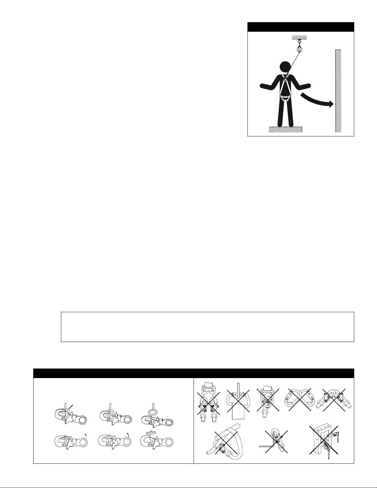
D. SWING FALLS: See Figure 3. Swing falls occur when the anchorage point is not directly above the point
where a fall occurs. The force of striking an object in a swing fall may cause serious injury or death.
Minimize swing falls by working as close to the anchorage point as possible. Do not permit a swing fall
if injury could occur. Swing falls will significantly increase the clearance required when a self retracting
lifeline or other variable length connecting subsystem is used.
1 Capacity: 310 lbs (141 kg) is the maximum capacity recommended by ANSI. This product has been tested to the OSHA recommended capacity of 420 lbs (191 kg).
2
Page 3
E. ENVIRONMENTAL HAZARDS: Use of this equipment in areas
with environmental hazards may require additional precautions
Figure 3 - Swing Falls
to prevent injury to the user or damage to the equipment.
Hazards may include, but are not limited to: heat, chemicals,
corrosive environments, high voltage power lines, gases, moving
machinery, and sharp edges. Contact DBI-SALA if you have
questions about using this equipment where environmental
hazards exist.
F. TRAINING: This equipment must be installed and used by
persons trained in its correct application and use. See section 4.0
Swing
Fall
Hazard
1.3 REFER TO NATIONAL STANDARDS INCLUDING: ANSI Z359
(.0, .1, .2, .3, and .4) family of standards on fall protection, ANSI
A10.32, and applicable local, state and federal (OSHA) requirements
governing occupational safety for more information about work
positioning systems.
2.0 SYSTEM REQUIREMENTS
2.1 COMPATIBILITY OF COMPONENTS: DBI-SALA equipment is designed for use with DBI-SALA approved
components and subsystems only. Substitutions or replacements made with non-approved components
or subsystems may jeopardize compatibility of equipment and may effect the safety and reliability of the
complete system.
2.2 COMPATIBILITY OF CONNECTORS: Connectors are considered to be compatible with connecting
elements when they have been designed to work together in such a way that their sizes and shapes do
not cause their gate mechanisms to inadvertently open regardless of how they become oriented. Contact
DBI-SALA if you have any questions about compatibility.
Connectors (hooks, carabiners, and D-rings) must be capable of supporting at least 5,000 lbs. (22kN).
Connectors must be compatible with the anchorage or other system components. Do not use equipment that
is not compatible. Noncompatible connectors may unintentionally disengage. See Figure 4. Connectors must
be compatible in size, shape, and strength. Self locking snap hooks and carabiners are required by ANSI
Z359.1 and OSHA.
2.3 MAKING CONNECTIONS: Only use self-locking snap hooks and carabiners with this equipment. Only use
connectors that are suitable to each application. Ensure all connections are compatible in size, shape and
strength. Do not use equipment that is not compatible. Ensure all connectors are fully closed and locked.
DBI-SALA connectors (snap hooks and carabiners) are designed to be used only as specifi ed in each
product’s user’s instructions. See Figure 5 for inappropriate connections. DBI-SALA snap hooks and
carabiners should not be connected:
A. To a D-ring to which another connector is attached.
B. In a manner that would result in a load on the gate.
NOTE: Large throat opening snap hooks should not be connected to standard size D-rings or similar
objects which will result in a load on the gate if the hook or D-ring twists or rotates. Large throat snap
hooks are designed for use on fi xed structural elements such as rebar or cross members that are not
shaped in a way that can capture the gate of the hook.
C. In a false engagement, where features that protrude from the snap hook or carabiner catch on the
anchor and without visual confirmation seems to be fully engaged to the anchor point.capture the gate
of the hook.
Figure 4 - Unintentional Disengagement Figure 5 - Inappropriate Connections
If the connecting element to which a snap hook (shown) or carabiner attaches
is undersized or irregular in shape, a situation could occur where the connecting
element applies a force to the gate of the snap hook or carabiner. This force may
cause the gate (of either a self-locking or a non-locking snap hook) to open,
allowing the snap hook or carabiner to disengage from the connecting point.
Small ring or other
non-compatibly
shaped element
A. B. C. D.
Force is applied to the
Snap Hook.
The Gate presses against
the Connecting Ring.
The Gate opens allowing
the Snap Hook to slip off.
E. F. G.
3
Page 4

D. To each other.
E. Directly to webbing or rope lanyard or tie-back (unless the manufacturer’s instructions for both the
lanyard and connector specifically allows such a connection).
F. To any object which is shaped or dimensioned such that the snap hook or carabiner will not close and
lock, or that roll-out could occur.
G. In a manner that does not allow the connector to align properly while under load.
2.4 PERSONAL FALL ARREST SYSTEM: Personal fall arrest systems used with this equipment must meet
applicable state, federal, OSHA, and ANSI requirements. A full body harness must be worn when this
equipment is used as a component of a personal fall arrest system. As required by OSHA, the personal fall
arrest system must be capable of arresting the user’s fall with a maximum arresting force of 1,800 lbs (8
kN), and limit the free fall to 6 ft. (1.8 m) or less. If the maximum free fall distance must be exceeded, the
employer must document, based on test data, that the maximum arresting force will not be exceeded, and
the personal fall arrest system will function properly.
When a free fall greater than 6 ft. (1.8 m), and up to a maximum of 12 ft (3.7 m) is possible, DBI-SALA
recommends using a personal fall arrest system incorporating a DBI-SALA Force2 Energy Absorbing Lanyard.
DBI-SALA has performed testing using the Force2 Energy Absorbing Lanyard in free falls up to 12 ft. (3.7 m) to
ensure the maximum arresting force does not exceed 1,800 lbs (8 kN), and the system functions properly. The
results of these tests are listed in the user instruction manual provided with Force2 Energy Absorbing Lanyards.
2.5 RESTRAINT SYSTEM: Restraint systems used with this equipment must meet state, federal, OSHA, and
ANSI requirements.
2.6 ANCHORAGE STRENGTH: The anchorage strength required is dependent on the application type. The
following are the requirements of ANSI 359.1 for these application types:
A. FALL ARREST : Anchorages selected for fall arrest systems shall have a strength capable of sustaining
static loads applied in the directions permitted by the system of at least:
1. 5,000 lbs. (22.2 kN) for non-certified anchorages, or
2. Two times the maximum arresting force for certified anchorages. When more than one fall arrest
system is attached to an anchorage, the strengths set forth in (1) and (2) above shall be multiplied by
the number of systems attached to the anchorage.
B. RESTRAINT: Anchorages selected for restraint and travel restraint systems shall have a strength
capable of sustaining static loads applied in the directions permitted by the system of at least:
1. 1,000 lbs. (4.5 kN) for non-certified anchorages, or
2. Two times the foreseeable force for certified anchorages. When more than one restraint and travel
restraint system is attached to an anchorage, the strengths set forth in (1) and (2) above shall be
multiplied by the number of systems attached to the anchorage.
C. WORK POSITIONING: Anchorages selected for work positioning systems shall have a strength capable
of sustaining static loads applied in the directions permitted by the system of at least: A) 3,000 pounds
(13.3kN) for non-certified anchorages or B) Two times the foreseeable force for certified anchorages
When more than one work positioning system is attached to an anchorage, the strengths previously set
forth in (A) and (B) shall be multiplied by the number of systems attached to the anchorage.
D. RESCUE: Anchorages selected for rescue systems shall have a strength capable of sustaining static
loads applied in the directions permitted by the system of at least:
1. 3,000 lbs. (13.3 kN) for non-certified anchorages, or
2. Five times the foreseeable force for certified anchorages. When more than one rescue system is
attached to an anchorage, the strengths set forth in (1) and (2) above shall be multiplied by the number
of systems attached to the anchorage.
WARNING: Mark or label the D-ring Anchorage Connector with the intended application. Use of this
equipment for an application that does not meet the anchorage strength requirements stated above may
result in serious injury or death.
3.0 INSTALLATION AND USE
WARNING: Do not alter or intentionally misuse this equipment. Consult DBI-SALA when using this equipment
in combination with components or subsystems other than those described in this manual. Some subsystem
and component combinations may interfere with the operation of this equipment. Use caution when using this
equipment around moving machinery, electrical and chemical hazards, and sharp edges.
WARNING: Consult with your doctor if there is reason to doubt your fi tness to safely absorb the shock from a
fall arrest. Age and fi tness seriously affect a worker’s ability to withstand falls. Pregnant women or minors must
not use the DBI-SALA D-ring Anchorage Connector.
4
Page 5

3.1 BEFORE EACH USE OF THIS EQUIPMENT inspect it according to section 5.0 of this manual.
3.2 PLAN YOUR SYSTEM BEFORE INSTALLATION: Consider all factors that will affect your safety during use
of this equipment. The following list gives important points to consider when planning your system:
A. ANCHORAGE: Select a rigid anchorage capable of supporting the loads specified in section 2.6.
B. SHARP EDGES: Avoid working where system components may be in contact with, or abrade against,
unprotected sharp edges.
C. AFTER A FALL: Any equipment which has been subjected to the forces of arresting a fall or exhibits
damage consistent with the effect of fall arrest forces as described in Section 5, must be removed from
service immediately and destroyed by the user, the rescuer, or an authorized person.
D. RESCUE: When using this equipment, the employer must have a rescue plan and the means at hand to
implement it and communicate that plan to users, authorized persons, and rescuers.
3.3 INSTALLATION REQUIREMENTS:
A. D-RING ANCHORAGE CONNECTOR
LOCATION: Select a location on a suitable
strength anchorage that will provide overall
safety and proper loading as shown in Figure 6.
The anchorage must be free of deformities or
defects that may weaken the structure.
B. INSTALLATION: The D-ring Anchorage
Connector may be attached to the structure
using fasteners or welding. Use fasteners that
will meet the strength requirements specified
in section 2.6. DBI-SALA recommends using
1/2-inch diameter, grade 5 bolts. Welded
installations must be installed by a certified
professional welder in accordance with the
latest codes and specifications of the American
Welding Society. Welds must support the
loads specified in section 2.6. Do not weld
the D-ring. The D-ring must swivel freely.
Welded installations should be verified by a
qualified person for strength by calculation or
by proof loading the installation in the intended
direction(s) of intended use to 3,600 lbs (16 kN). Protect finished welds from corrosion with paint or
other finish. Do not electroplate the D-ring. Installations should be verified by a qualified person for
strength by calculation in the intended direction(s) of intended use.
3.4 MAKING CONNECTIONS: When using a hook to connect to the D-ring Anchorage Connector, ensure rollout cannot occur. Roll-out occurs when interference between the hook and mating connector causes the
hook gate to unintentionally open and release. Self locking snap hooks and carabiners should be used to
reduce the possibility of roll-out. Do not use hooks or connectors that will not completely close over the
attachment object. See subsystem manufacturer’s instructions for information on connecting to the D-ring
Anchorage Connector.
Figure 6 - D-Ring Anchorage Connector Loads
Load
Load
Load
Proper Loading
Load
Improper Loading
4.0 TRAINING
4.1 It is the responsibility of the user and the purchaser of this equipment to assure that they are familiar with
these instructions, trained in the correct care and use of, and are aware of the operating characteristics,
application limits, and the consequences of improper use of this equipment.
IMPORTANT: Training must be conducted without exposing the user to a fall hazard. Training should be
repeated on a periodic basis.
5.0 INSPECTION
5.1 FREQUENCY:
• Before Each Use: Inspect the D-ring Anchorage Connector according to sections 5.2 and 5.3.
• Formal Inspection: A formal inspection of the D-ring Anchorage Connector and its connection to
the structure must be performed at least annually by a competent person other than the user. The
frequency of formal inspections should be based on conditions of use or exposure. See sections 5.2 and
5.3. Record the inspection results in the inspection and maintenance log in section 9.0.
5
Page 6

5.2 INSPECTIONS STEPS:
Step 1. Inspect the D-ring for damage or corrosion. Inspect for cracks or wear that may affect strength
and operation.
Step 2. Inspect the Anchorage Plate for damage or corrosion. Inspect for cracks or wear that may affect
strength and operation.
Step 3. Inspect the attaching fasteners. Fasteners must hold the Anchorage Plate securely to the
anchorage. Inspect for damage or corrosion.
Step 4. Inspect the labels all labels must be present and fully legible.
Step 5. Inspect the system components according to the manufacturer’s instructions.
Step 6. Record the inspection results in the Inspection & Maintenance Log at the back of this manual.
5.3 If inspection reveals an unsafe or defective condition, remove the D-ring Anchorage Connector from service
and destroy it.
6.0 MAINTENANCE
6.1 CLEANING: Clean the D-ring Anchorage Connector with a mild soap solution. Excessive build-up of dirt may
prevent the D-ring from swivelling.
7.0 SPECIFICATIONS
Model D-Ring Material Anchorage Plate Material
2101630 Alloy Steel, 5,000 lbs (22.2 kN) Stainless Steel; UNS S30400 or UNS S30403 per ASTM A276
2101632 Alloy Steel, 5,000 lbs (22.2 kN) Hot Rolled Steel, Painted Black: ASTM A36 or ASTM A529
2101633 Alloy Steel, 5,000 lbs (22.2 kN) Stainless Steel; UNS S30400 or UNS S30403 per ASTM A276
2101634 Alloy Steel, 5,000 lbs (22.2 kN) Hot Rolled Steel: ASTM A36 or ASTM A529
2101636 Stainless Steel; UNS S30400 or UNS S30403 per ASTM A276 Stainless Steel; UNS S30400 or UNS S30403 per ASTM A276
2101638 Stainless Steel; UNS S30400 or UNS S30403 per ASTM A276 Stainless Steel; UNS S30400 or UNS S30403 per ASTM A276
2109870 Stainless Steel; UNS S30400 or UNS S30403 per ASTM A276 Stainless Steel; UNS S30400 or UNS S30403 per ASTM A276
7.1 DIMENSIONS :
0.75”
1.91 cm
3.00”
7.62 cm
4.50”
11.43 cm
1.00”
2.54 cm
4.23”
10.74 cm
0.56”
1.43 cm
2.00”
5.08 cm
3.29”
8.36 cm
2.25”
5.72 cm
8.0 LABELING
6
Page 7

INSPECTION AND MAINTENANCE LOG
SERIAL NUMBER:
MODEL NUMBER:
DATE PURCHASED: DATE OF FIRST USE:
INSPECTION DATE INSPECTION ITEMS
NOTED
Approved By:
Approved By:
Approved By:
Approved By:
Approved By:
Approved By:
Approved By:
Approved By:
CORRECTIVE ACTION MAINTENANCE
PERFORMED
Approved By:
Approved By:
Approved By:
Approved By:
Approved By:
Approved By:
Approved By:
Approved By:
Approved By:
Approved By:
Page 8

LIMITED LIFETIME WARRANTY
Warranty to End User: D B Industries, Inc., dba CAPITAL SAFETY USA (“CAPITAL SAFETY”) warrants to the
original end user (“End User”) that its products are free from defects in materials and workmanship under
normal use and service. This warranty extends for the lifetime of the product from the date the product is
purchased by the End User, in new and unused condition, from a CAPITAL SAFETY authorized distributor.
CAPITAL SAFETY’S entire liability to End User and End User’s exclusive remedy under this warranty is limited
to the repair or replacement in kind of any defective product within its lifetime (as CAPITAL SAFETY in its sole
discretion determines and deems appropriate). No oral or written information or advice given by CAPITAL
SAFETY, its distributors, directors, offi cers, agents or employees shall create any different or additional
warranties or in any way increase the scope of this warranty. CAPITAL SAFETY will not accept liability for defects
that are the result of product abuse, misuse, alteration or modifi cation, or for defects that are due to a failure to
install, maintain, or use the product in accordance with the manufacturer’s instructions.
CAPITAL SAFETY’S WARRANTY APPLIES ONLY TO THE END USER. THIS WARRANTY IS THE ONLY WARRANTY
APPLICABLE TO OUR PRODUCTS AND IS IN LIEU OF ALL OTHER WARRANTIES AND LIABILITIES, EXPRESSED
OR IMPLIED. CAPITAL SAFETY EXPRESSLY EXCLUDES AND DISCLAIMS ANY IMPLIED WARRANTIES OF
MERCHANTABILITY OR FITNESS FOR A PARTICULAR PURPOSE, AND SHALL NOT BE LIABLE FOR INCIDENTAL,
PUNITIVE OR CONSEQUENTIAL DAMAGES OF ANY NATURE, INCLUDING WITHOUT LIMITATION, LOST PROFITS,
REVENUES, OR PRODUCTIVITY, OR FOR BODILY INJURY OR DEATH OR LOSS OR DAMAGE TO PROPERTY, UNDER
ANY THEORY OF LIABILITY, INCLUDING WITHOUT LIMITATION, CONTRACT, WARRANTY, STRICT LIABILITY, TORT
(INCLUDING NEGLIGENCE) OR OTHER LEGAL OR EQUITABLE THEORY.
CSG USA & Latin America
3833 SALA Way
Red Wing, MN 55066-5005
Toll Free: 800.328.6146
Phone: 651.388.8282
Fax: 651.388.5065
solutions@capitalsafety.com
CSG EMEA
(Europe, Middle East, Africa)
Le Broc Center
Z.I. 1ère Avenue
5600 M B.P. 15 06511
Carros
Le Broc Cedex
France
Phone: + 33 4 97 10 00 10
Fax: + 33 4 93 08 79 70
information@capitalsafety.com
The Ultimate in Fall Protection
CSG Canada
260 Export Boulevard
Mississauga, ON L5S 1Y9
Phone: 905.795.9333
Toll-Free: 800.387.7484
Fax: 888.387.7484
info.ca@capitalsafety.com
CSG Australia & New Zealand
95 Derby Street
Silverwater
Sydney NSW 2128
AUSTRALIA
Phone: +(61) 2 8753 7600
Toll-Free : 1 800 245 002 (AUS)
Toll-Free : 0800 212 505 (NZ)
Fax: +(61) 2 87853 7603
sales@capitalsafety.com.au
www.capitalsafety.com
CSG Northern Europe
5a Merse Road
North Moons, Moat
Reditch, Worcestershire, UK
B98 9HL
Phone: + 44 (0)1527 548 000
Fax: + 44 (0)1527 591 000
csgne@capitalsafety.com
CSG Asia
Singapore:
16S, Enterprise Road
Singapore 627666
Phone: +65 - 65587758
Fax: +65 - 65587058
inquiry@capitalsafety.com
Shanghai:
Rm 1406, China Venturetech Plaza
819 Nan Jing Xi Rd,
Shanghai 200041, P R China
Phone: +86 21 62539050
Fax: +86 21 62539060
ISO
9001
Certificate No. FM 39709
 Loading...