

Page 1
Instructions for the
following series products:
ExoFit Full Body Harnesses
(See back pages for specic
model numbers.)
This manual is intended to meet
the Manufacturer’s Instructions as
required by ANSI Z359 and should
be used as part of an employee
training program as required by
OSHA.
© Copyright 2008, DB Industries, Inc.
Page 2

Page 3

WARNING: This product is part of a personal restraint, work
positioning, suspension, or rescue system. These instructions must be
provided to the user and rescuer (see section 8.0 Terminology). The user
must read and understand these instructions or have them explained to
them before using this equipment. The user must read and follow the
manufacturer’s instructions for each component or part of the complete
system. Manufacturer’s instructions must be followed for proper use and
maintenance of this product. Alterations or misuse of this product or
failure to follow instructions may result in serious injury or death.
IMPORTANT: If you have questions on the use, care, or suitability of
this equipment for your application, contact DBI‑SALA.
IMPORTANT: Before using this equipment, record the product
identication information from the ID label into the inspection and
maintenance log in section 10.0 of this manual.
DESCRIPTIONS
ExoFit Vest Style Full Body Harness: See Figure 1.
ExoFit Cross-Over Style Full Body Harness: See Figure 2.
OPTIONS:
DBI-SALA ExoFit and ExoFit XP Full Body Harnesses are available
with options and accessories. Following is a partial list of
commonly used options and accessories (some options may not
be available on all harnesses):
• Side D-rings
• Front D-rings
• Hip pad with side D-rings
• Tongue buckle body belt
• Lanyard attached directly to D-ring or attachment element
3
Page 4
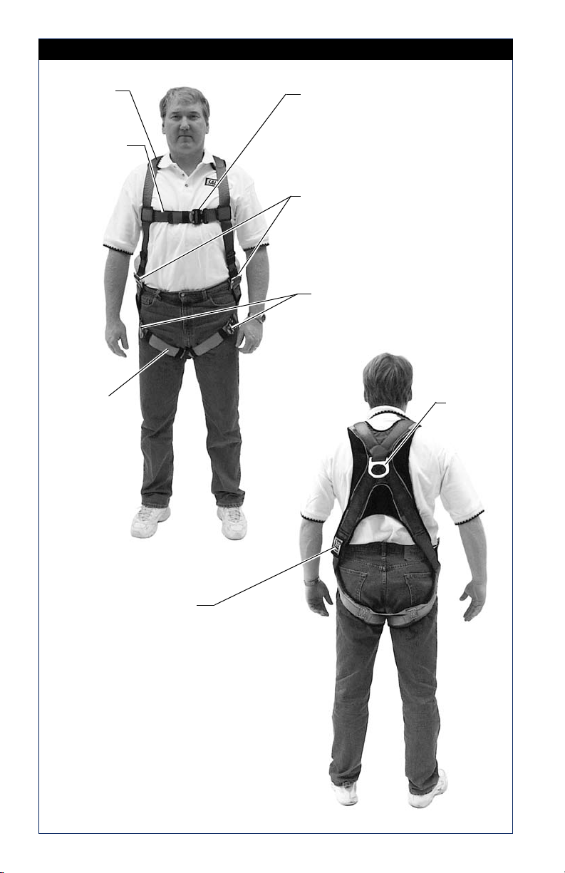
Figure 1 - ExoFit Vest Style Full Body Harness
Shoulder
Strap
Chest Strap
Leg Strap
Quick Connect Buckle
Parachute
Buckle
Quick Connect Buckle
Dorsal
D-ring
Product Warning and
Identification Labels
4
Page 5
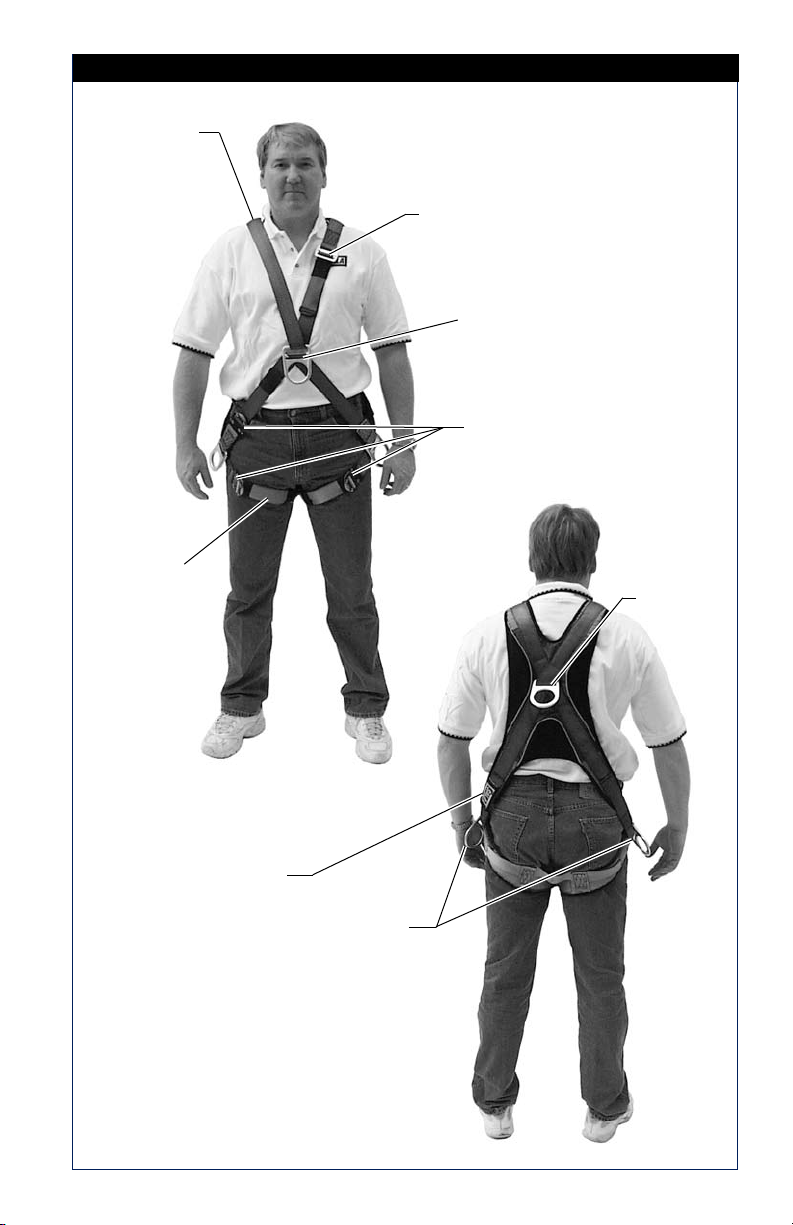
Figure 2 - ExoFit Cross-Over Style Full Body Harness
Shoulder
Strap
Parachute
Buckle
Front Attachment Element
(D-ring Or Web Loop)
Quick Connect Buckle
Leg Strap
Dorsal
D-ring
Product Warning and
Identification Labels
Side
D-rings
5
Page 6
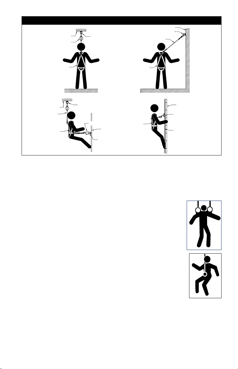
1.0 APPLICATIONS
1.1 PURPOSE: DBI-SALA ExoFit and ExoFit XP full body harnesses are
to be used as components in personal fall arrest, restraint, work
positioning, climbing, or rescue systems. See Figures 1 and 2 for
harness styles.
Harnesses included in this manual are full body harnesses and
meet ANSI Z359.1 and OSHA requirements. See Figure 3 for
application illustrations.
WARNING: Working at height has inherent risks. Some risks are
noted here but are not limited to the following: falling, suspension/
prolonged suspension, striking objects, and unconsciousness. In the
event of a fall arrest and/or subsequent rescue (emergency) situation,
some personal medical conditions may affect your safety. Medical
conditions identied as risky for this type of activity include but are not
limited to the following: heart disease, high blood pressure, vertigo,
epilepsy, drug or alcohol dependence, psychiatric illness, impaired
limb function and balance issues. We recommend that your employer/
physician determine if you are t to handle normal and emergency use
of this equipment.
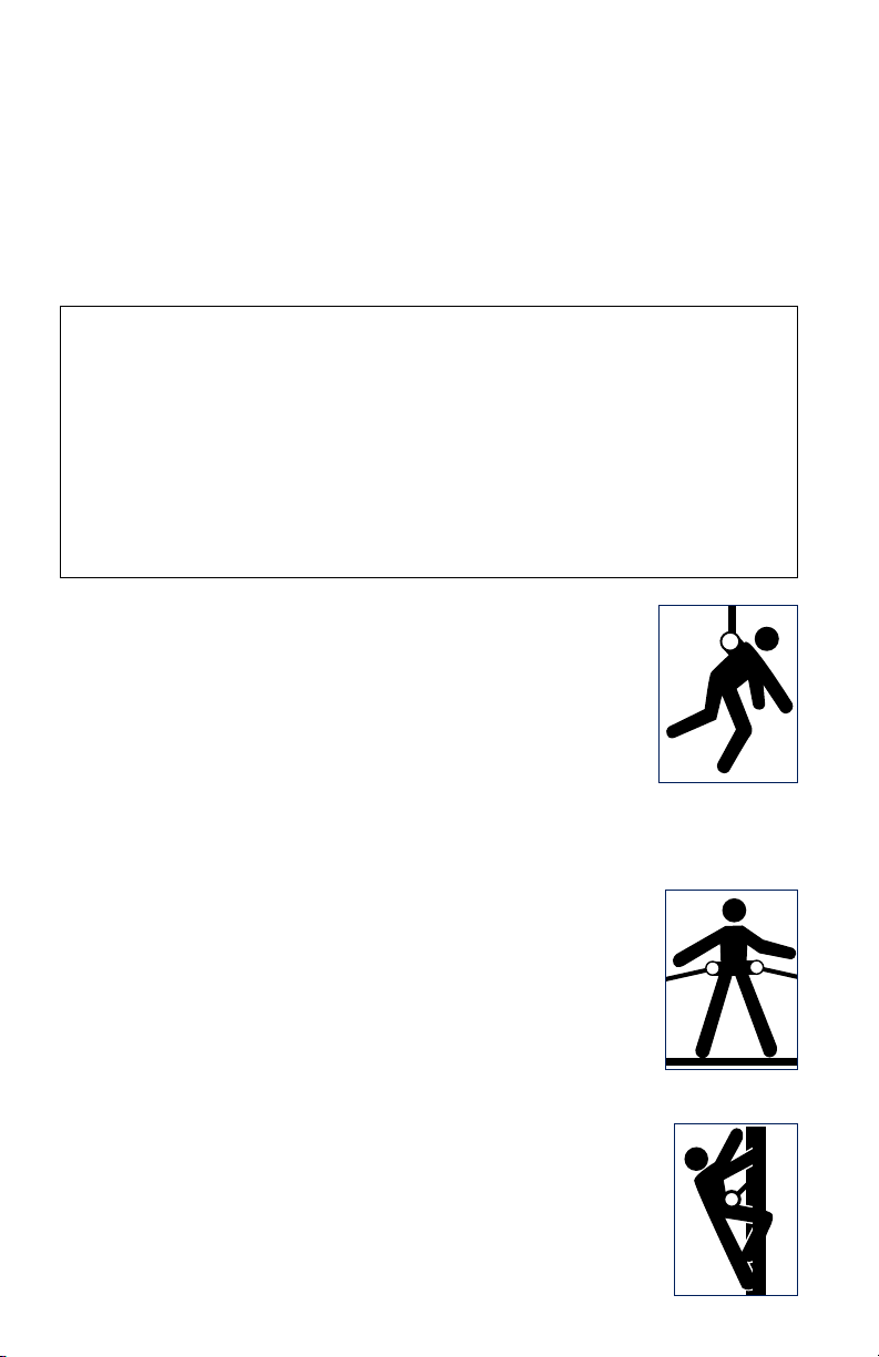
A. PERSONAL FALL ARREST: The full body
harness is used as a component of a personal
fall arrest system. Personal fall arrest systems
typically include a full body harness and a
connecting subsystem (energy absorbing
lanyard). Maximum arresting force must not
exceed 1,800 lbs (8 kN).For fall protection
applications connect the fall arrest subsystem
(example: lanyard, SRL, energy absorber, etc.)
to the D-ring or attachment element on your back, between
your shoulder blades.
B. WORK POSITIONING: The full body harness
is used as a component of a work positioning
system to support the user at a work position.
Work positioning systems typically include a full
body harness, positioning lanyard, and a back-up
personal fall arrest system. For work positioning
applications, connect the work positioning
subsystem (example: lanyard, Y-lanyard, etc.) to
the lower (hip level) side or belt mounted work
positioning attachment anchorage elements (D-rings). Never
use these connection points for fall arrest.
C. LADDER CLIMBING: The full body harness
is used as a component of a climbing system
to prevent the user from falling when climbing
a ladder or other climbing structure. Climbing
systems typically include a full body harness,
6
Page 7
Anchorage
Connecting Subsystem
(Self Retracting
Lifeline Shown)
Figure 3 - Applications
Anchorage Connector
Anchorage Connector
Restraint Lanyard
Anchorage
Full Body Harness
Fall Arrest
Anchorage
Back-up
Fall Arrest
System
Full Body
Harness
Work Positioning
Anchorage
Connector
Restraint Lanyard
Anchorage
Connector
Anchorage
Full Body Harness
Restraint
Cross-over
Full Body
Harness
Ladder Climbing
Ladder
Cable Sleeve
Cable
vertical cable or rail attached to the structure, and climbing
sleeve.For ladder climbing applications, harnesses equipped
with a frontal D-ring in the sternal location may be used
for fall arrest on xed ladder climbing systems. These are
dened in ANSI A14.3.
D. RESCUE: The full body harness is used as a
component of a rescue system. Rescue systems
are configured depending on the type of rescue.
For limited access (conned space) applications,
harnesses equipped with D-rings on the shoulders
may be used for entry and egress into conned
spaces where worker prole is an issue.
E. CONTROLLED DESCENT: For controlled descent
applications, harnesses equipped with a single
sternal level D-ring, one or two frontal mounted
D-rings, or a pair of connectors originating below
the waist (such as a seat sling) may be used for
connection to a descender or evacuation system.
E. RESTRAINT: The full body harness is used as a
component of a restraint system to prevent the
user from reaching a fall hazard. Restraint systems typically
include a full body harness and a lanyard or restraint line.
1.2 LIMITATIONS: Consider the following application limitations
before using this equipment:
7
Page 8
A. CAPACITY: These full body harnesses are designed for
use by persons with a combined weight (clothing, tools,
etc.) of no more than 420 lbs. (191 kg) Make sure all of
the components in your system are rated to a capacity
appropriate to your application.
B. FREE FALL: Personal fall arrest systems used with this
equipment must be rigged to limit the free fall to 6 feet
(ANSI Z359.1). Restraint systems must be rigged so that
no vertical free fall is possible. Work positioning systems
must be rigged so that free fall is limited to 2 feet (.6 m)
or less. Personnel riding systems must be rigged so that
no vertical free fall is possible. Climbing systems must be
rigged so that free fall is limited to 18 inches (.5 m) or less.
Rescue systems must be rigged so that no vertical free fall
is possible. See subsystem manufacturer’s instructions for
more information.
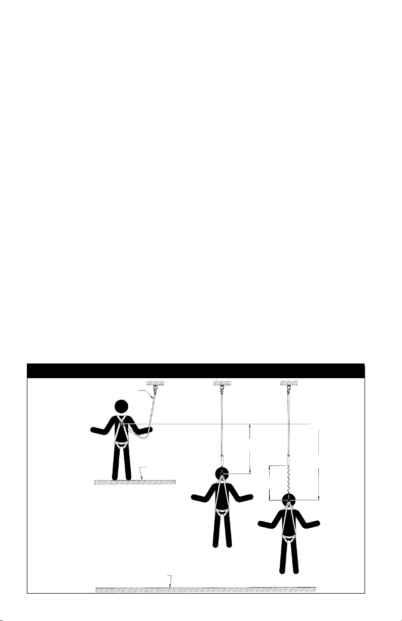
C. FALL CLEARANCE: See Figure 4. There must be sufficient
clearance below the user to arrest a fall before the user
strikes the ground or other obstruction. The clearance
required is dependent on the following factors:
• Elevation of anchorage • Connecting subsystem length
• Deceleration distance • Free fall distance
• Worker height • Movement of harness
attachment element
See subsystem manufacturer’s instructions for more information.
Figure 4 - Fall Clearance
(Energy Absorbing Lanyard shown)
Connecting Subsystem
Lower Level or Obstruction
Working Level
Free Fall
6 ft. max (ANSI Z359.1)
Deceleration
Distance
Total Fall Distance
(Free Fall + Deceleration)
8
Page 9
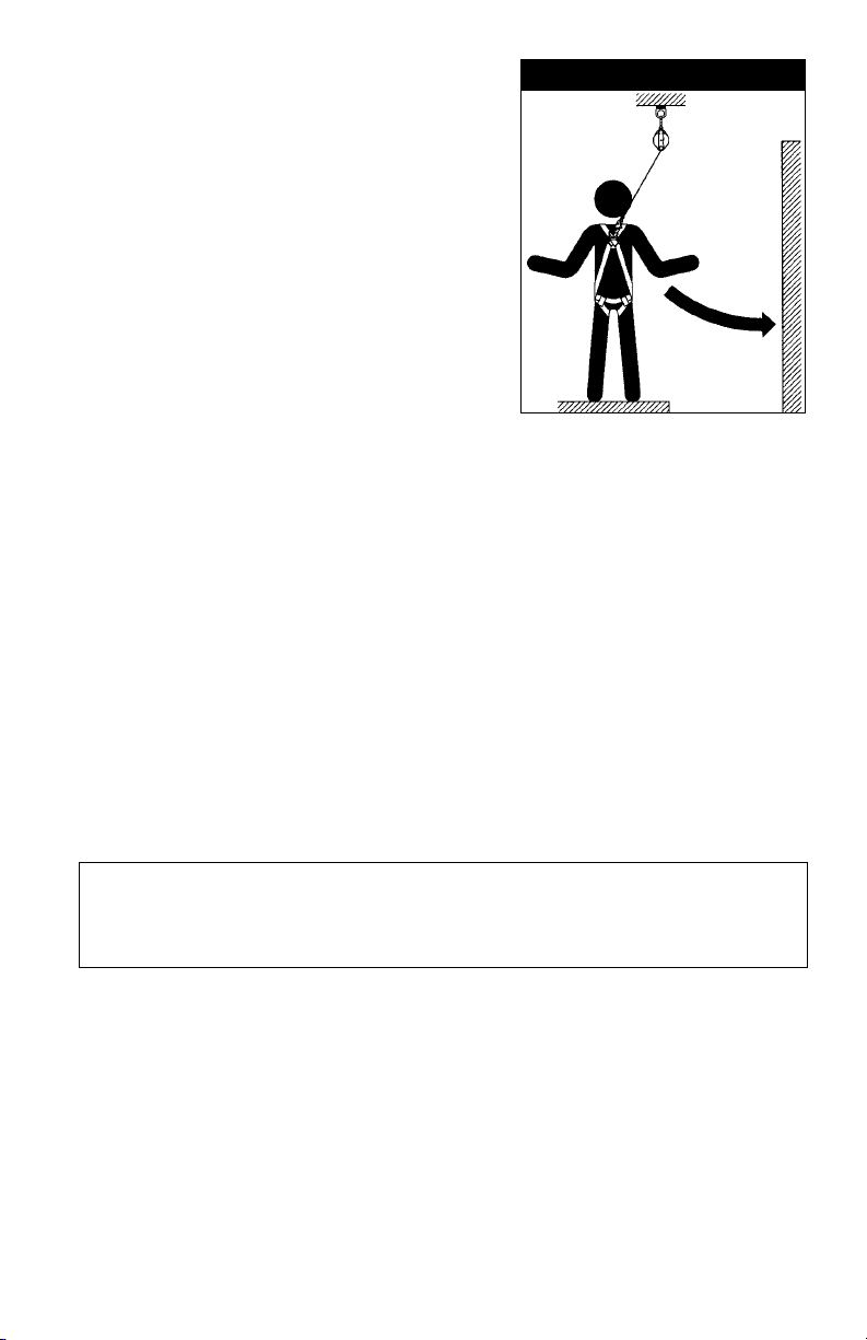
D. SWING FALLS: See Figure 5.
Swing falls occur when the
anchorage point is not directly
above the point where a fall
occurs. The force of striking
an object in a swing fall may
cause serious injury or death.
Minimize swing falls by working
as close to the anchorage point
as possible. Do not permit a
swing fall if injury could occur.
Swing falls will significantly
increase the clearance required
when a self retracting lifeline or
other variable length connecting
subsystem is used.
E. EXTENDED SUSPENSION: A full body harness is not
intended for use in extended suspension applications. If the
user is going to be suspended for an extended length of
time it is recommended that some form of seat support be
used. DBI-SALA recommends a seat board, suspension work
seat, seat sling, or a boatswain chair. Contact DBI-SALA for
more information on these items.
F. ENVIRONMENTAL HAZARDS: Use of this equipment in
areas with environmental hazards may require additional
precautions to prevent injury to the user or damage to the
equipment. Hazards may include, but are not limited to;
heat, chemicals, corrosive environments, high voltage power
lines, gases, moving machinery, and sharp edges.
Figure 5 - Swing Fall
Swing
Fall
Hazard
G.
TRAINING: This equipment must be installed and used by
persons trained in its correct application and use. See section 4.0.
IMPORTANT: When working with tools, materials, or in high
temperature environments, ensure that associated fall protection
equipment can withstand high temperatures, or provide
protection for those items.
1.3
Refer to national Standards including ANSI Z359 (.0, .1, .2, .3, and
.4) family of standards on fall protection, ANSI A10.32, and applicable
local, state and federal (OSHA) requirements governing occupational
safety for more information about work positioning systems.
2.0 SYSTEM REQUIREMENTS
2.1 COMPATIBILITY OF COMPONENTS: DBI-SALA equipment
is designed for use with DBI-SALA approved components and
subsystems only. Substitutions or replacements made with nonapproved components or subsystems may jeopardize compatibility
of equipment and may effect the safety and reliability of the
complete system.
9
Page 10
2.2 COMPATIBILITY OF CONNECTORS: Connectors are considered
to be compatible with connecting elements when they have been
designed to work together in such a way that their sizes and
shapes do not cause their gate mechanisms to inadvertently open
regardless of how they become oriented. Contact DBI-SALA if you
have any questions about compatibility.
Connectors (hooks, carabiners, and D-rings) must be capable
of supporting at least 5,000 lbs. (22.2kN). Connectors must be
compatible with the anchorage or other system components. Do not
use equipment that is not compatible. Non-compatible connectors
may unintentionally disengage. See Figure 6. Connectors must be
compatible in size, shape, and strength. Self locking snap hooks
and carabiners are required by ANSI Z359.1 and OSHA.
2.3 MAKING CONNECTIONS: Only self-locking snap hooks and/or
carabiners shall be used with this equipment. Ensure all connectors
are fully closed and locked and compatible.
DBI-SALA connectors (snap hooks and carabiners) are designed to
be used only as specied in each product’s user instructions. See
Figure 3 for inappropriate connections. DBI-SALA snap hooks and
carabiners should not be connected:
A. To a D-ring which another connector is already attached.
B. In a manner that would result in a load on the gate.
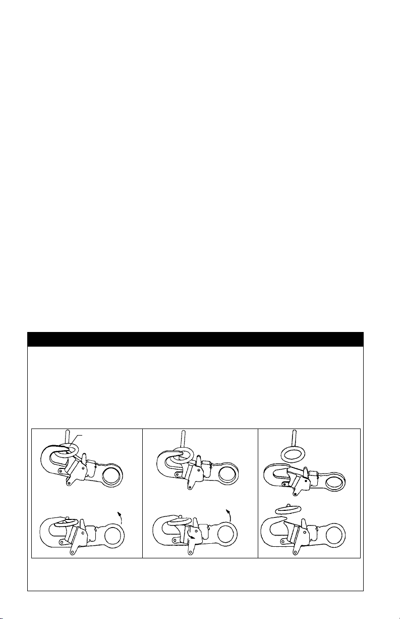
Figure 6 - Unintentional Disengagement (Roll-out)
If the connecting element that a snap hook (shown) or carabiner attaches to is
undersized or irregular in shape, a situation could occur where the connecting
element applies a force to the gate of the snap hook or carabiner. This force
may cause the gate (of either a self-locking or a non-locking snap hook) to
open, allowing the snap hook or carabiner to disengage from the connecting
point. For ANSI Z359.1-2007 compliant hooks, there are no restrictions on the
size or shape of the mating connector provided the snap hook is free to align
with the applied load as intended.
Small ring or other
non-compatibility
connector
1. Force is applied to
the snap hook.
2. The gate presses against
the connecting ring.
3. The gate opens
allowing the snap hook
to slip off.
10
Page 11

Figure 7 - Inappropriate Connections
NOTE: Large throat snap hooks should not be connected to standard
size D‑rings or similar objects which will result in a load on the gate
if the hook or D‑ring twists or rotates, unless the snap hook complies
with ANSI Z359.1‑2007 and is equipped with a 3,600 lb gate. Check
the marking on your snap hook to verify that it is appropriate for your
application.
C. In a false engagement, where features that protrude from
the snap hook or carabiner catch on the D-ring, and without
visual confirmation seems to be fully engaged to the anchor
point.
D. To each other.
E. Directly to webbing or rope lanyard for tie-back (unless
specifically provided by the manufacturer).
F. To any object which is shaped or dimensioned such that the
snap hook or carabiner will not close and lock, or where roll-
out could occur.
OTHER RESTRICTIONS:
• Do not make connections where the hook locking mechanism
can come into contact with a structural member or other
equipment and potentially release the hook.
•
Do not connect a snap hook into a loop or thimble of a wire rope
or attach in any way to a slack wire rope.
• The snap hook must be free to align with the applied load
as intended (regardless of the size or shape of the mating
connector).
• A caribiner may be used to connect to a single or pair of soft
loops on a body support such as a body belt or full body harness,
provided the carabiner can fully close and lock. This type of
connection is not allowed for snap hooks.
11
Page 12

• A carabiner may be connected to a loop or ring connector that
is already occupied by a choker style connector. This type of
connection is not allowed for snap hooks.
2.4 CONNECTING SUBSYSTEMS: Connecting subsystems (selfretracting lifeline, lanyard, rope grab and lifeline, cable sleeve)
must be suitable for your application. See section 1.1. See
subsystem manufacturer’s instructions for more information. Some
harness models have web loop connection points. Do not use
snap hooks to connect to web loops. Use a self-locking carabiner
to connect to a web loop. Ensure the carabiner cannot cross-
gate load (load against
Figure 8 - Web Loop Connection
the gate rather than
along the backbone
of the carabiner).
Some lanyards are
designed to choke onto
a web loop to provide a
compatible connection.
Insert lanyard web loop
through web loop or
D-ring on harness
Harness Web
Loop or D-ring
Energy Absorbing Lanyard
Web Loop on
See Figure 8. Lanyards
may be sewn directly to
the web loop forming a
permanent connection.
Insert opposite end of lanyard through the
lanyard web loop
Do not make multiple
connections onto one
web loop, unless choking
two lanyards onto a
properly sized web loop.
Pull the lanyard through the connecting web loop
to secure
2.5 ANCHORAGE STRENGTH: The anchorage strength required
is dependent on the application type. The following are the
requirements of ANSI 359.1 for these application types:
A. FALL ARREST: Anchorages selected for fall arrest systems
shall have a strength capable of sustaining static loads
applied in the directions permitted by the system of at least:
1. 5,000 lbs. (22.2 kN) for non-certified anchorages, or
2. Two times the maximum arresting force for certified
anchorages. When more than one fall arrest system is
attached to an anchorage, the strengths set forth in (1)
and (2) above shall be multiplied by the number of systems
attached to the anchorage.
B. RESTRAINT: Anchorages selected for restraint and travel
restraint systems shall have a strength capable of sustaining
static loads applied in the directions permitted by the system
of at least:
1. 1,000 lbs. (4.5 kN) for non-certied anchorages, or
2. Two times the foreseeable force for certied anchorages.
When more than one restraint and travel restraint system
is attached to an anchorage, the strengths set forth in (1)
and (2) above shall be multiplied by the number of systems
attached to the anchorage.
12
Page 13

C. WORKING POSITIONING: Anchorages selected for work
positioning systems shall have a strength capable of sustaining
static loads applied in the directions permitted by the system
of at least:
1. 3,000 lbs. (13.3 kN) for non-certied anchorages, or
2. Two times the foreseeable force for certied anchorages.
When more than one work positioning system is attached to
an anchorage, the strengths set forth in (1) and (2) above
shall be multiplied by the number of systems attached to the
anchorage.
D. RESCUE: Anchorages selected for rescue systems shall have
a strength capable of sustaining static loads applied in the
directions permitted by the system of at least:
1. 3,000 lbs. (13.3 kN) for non-certified anchorages, or
2. Five times the foreseeable force for certified anchorages.
When more than one rescue system is attached to an
anchorage, the strengths set forth in (1) and (2) above shall
be multiplied by the number of systems attached to the
anchorage.
E. CLIMBING: The structure to which a climbing system
is attached must sustain the loads required by that
particular system. See instructions for climbing system for
requirements.
3.0 DONNING AND USE
WARNING: Do not alter or intentionally misuse this equipment. Consult
DBI‑SALA when using this equipment in combination with components or
subsystems other than those described in this manual. Some subsystem
and component combinations may interfere with the operation of this
equipment. Use caution when using this equipment around moving
machinery, electrical and chemical hazards, and sharp edges.
Figure 9 - Front and Back View of ExoFit Vest Style Full Body Harness
Belt Loops
Front
Back
13
Page 14

3.1 BEFORE EACH USE of this equipment inspect it according to
section 5.0 of this manual.
3.2 PLAN your system before use. Consider all factors that will affect
your safety during use of this equipment. The following list gives
important points to consider when planning your system:
A. ANCHORAGE: Select an anchorage that meets the
requirements specified in sections 1.2 and 2.5.
B. SHARP EDGES: Avoid working where system components
may be in contact with, come in contact with, or abrade
against, unprotected sharp edges.
C. AFTER A FALL: Any equipment which has been subjected
to the forces of arresting a fall or exhibits damage
consistent with the effect of fall arrest forces as described in
section 5.0, must be removed from service immediately and
destroyed by the user, the rescuer, or an authorized person.
D. RESCUE: The employer must have a rescue plan when
using this equipment. The employer must have the ability to
perform a rescue quickly and safely.
3.3 DONNING AND FITTING THE HARNESS:
A. ExoFit Vest Style Full Body Harness: See Figure 9 for
front and back views of the ExoFit Vest style full body
harness. Your harness incorporates loops for a removable
waist belt. The belt can be installed through the two loops in
the harness located in the lower back shoulder straps. The
belt will pass through the harness just below the padded
area. The hip pad, if used, is secured to the belt by passing
the belt through the hip pad loops.
Don the ExoFit Vest style full body harness by following
these steps (see Figures 10 and 11):
Step 1. Locate back D-ring held in position by the D-ring pad; lift
up harness and hold by this D-ring. Ensure the straps are
not twisted.
Step 2. Grasp the shoulder straps and slip the harness onto one
arm. The D-ring will be located on your back side. Ensure
that the straps are not tangled and hang freely. Slip
your free arm into the harness and position the shoulder
straps on top of your shoulder. Ensure that the straps are
not tangled and hang freely. The chest strap, with quick
connect buckle, will be positioned on the front side when
worn properly.
Step 3. Reach between your legs and grasp the gray leg strap
on your left side. Bring the strap up between your legs
and connect it by inserting the tab of the buckle into
14
Page 15

Figure 10 - Donning ExoFit Vest Style Full Body Harness
Step 1
Step 2
Step 3
Step 3
Step 4 Step 5
15
Page 16

Figure 11 - ExoFit Quick Connect Buckle Connections
Chest Strap: Attach chest strap by
inserting the tab of the buckle into
the receptor of the quick connect
buckle until a click is heard
Leg Straps: Attach leg strap by
inserting the tab of the buckle into
the receptor of the quick connect
buckle until a click is heard
receptor of quick connect buckle on the left side as shown
in Figure 10. You will hear a click when the tab engages
properly. Connect the right leg strap using the same
procedure. Pull the free end of the strap away from the
buckle to make a snug t on each leg strap. To loosen the
leg strap, grasp the yellow plastic portion of the buckle
and pull away from your leg to allow the strap to pull
through the buckle. A plastic end keeper on the end of the
strap will stop it from pulling completely out of the buckle.
To release the buckle, press the silver-colored tabs on the
buckle towards each other with one hand, while pulling on
the tab portion of the buckle with the other hand.
Step 4. Attach the chest strap by inserting the tab of the buckle
into the receptor of the quick connect buckle. You will
hear a click when the tab engages properly. The chest
strap should be 6 in. (15 cm) down from the top of your
shoulders. Pass excess strap through the loop keepers.
The strap may be tightened to a snug t by pulling the
free strap end to the left
(away from the buckle).
Figure 12 - ExoFit Cross-Over Style
To loosen the chest strap,
grasp the yellow plastic
portion of the buckle and
pull away from the body
to allow the strap to pull
through the buckle. A
plastic end keeper on the
end of the strap will stop
it from pulling completely
out of the buckle. To
release the buckle, press
the silver-colored tabs on
the buckle toward each
other with one hand, while
pulling on the tab portion
of the buckle with the other
hand.
Belt Loops
16
Page 17

Figure 13 - Donning ExoFit Cross-Over Style Full Body Harness
Step 1 Step 2
Step 4
Step 3
Step 5
17
Page 18

Step 5. Adjust shoulder straps to a snug t by pulling excess
strap through the parachute buckles on each side of the
harness. Left and right sides of shoulder straps should be
adjusted to the same length and the chest strap should
be centered on your lower chest, 6 in. (15 cm) down from
shoulder. The front D-ring on the vest style harness is
moved up or down by adjusting the shoulder straps and
leg straps. Center the back D-ring between your shoulder
blades. Note: On ExoFit XP models, the back (dorsal)
D-ring can be repositioned up or down as needed for a
correct t. Adjust leg straps to a snug t. At least 3 in.
(8 cm) of webbing must extend past the buckle on the leg
straps. Adjust the waist belt (if present).
B. EXOFIT CROSS-OVER STYLE FULL BODY HARNESS:
Your harness incorporates loops for a removable waist
belt. The belt can be installed through the two loops in
the harness located in the lower back shoulder straps, see
Figure 12. The belt will pass through the harness just below
the padded area. The hip pad, if used, is secured to the
belt by passing the belt through the hip pad loops. Don the
ExoFit Cross-Over style full body harness by following these
steps (see Figures 13 and 14):
Step 1. Locate the back D-ring held in position by the D-ring pad;
lift up the harness and hold by this D-ring. Ensure the
straps are not twisted.
Step 2.
Grasp the shoulder straps between the back and front
D-ring and slip the harness over your head from the left
side. Position the shoulder straps on top of your shoulders.
Ensure that the straps are not tangled and hang freely. The
D-ring will be positioned on your back when worn properly.
Step 3. Grasp the tab of the buckle located at your right hip and
insert it into the receptor of the quick connect buckle,
see Figure 13. You will hear a click when the tab engages
properly.
Figure 14 - ExoFit Quick Connect Buckle Connections
Hip Strap: Attach chest strap
by inserting the tab of the
buckle into the receptor of the
quick connect buckle until a
click is heard
Leg Straps: Attach leg strap by
inserting the tab of the buckle
into the receptor of the quick
connect buckle until a click is
heard
18
Page 19

Step 4. Reach between your legs and grasp the gray leg strap on
your left side. Bring the strap up between your legs and
insert the tab of the buckle into the receptor of the buckle
on the left side as shown in Figure 13. You will hear a click
when the tab engages properly. Connect the right leg strap
using the same procedure. Pull the free end of the strap
away from the buckle to make a snug t on each leg strap.
To loosen the leg strap, grasp the yellow plastic portion of
the buckle and pull away from your leg to allow the strap
to pull through the buckle. A plastic end keeper on the end
of the strap will stop it from pulling completely out of the
buckle. To release the buckle, press the silver-colored tabs
on the buckle towards each other with one hand, while
pulling on the tab portion of the buckle with the other hand.
Step 5. Adjust shoulder strap to a snug t by pulling excess strap
through the parachute buckle. Left and right sides of the
shoulder straps should be adjusted to the same length
and the front D-ring should be centered on your lower
chest. The back D-ring should be centered between your
shoulder blades. Note: On ExoFit XP models, the back
(dorsal) D-ring can be repositioned up or down as needed
for a correct t. Adjust the leg straps to a snug t. At least
3 in. (8 cm) of webbing must extend past the buckle on
the leg straps. Adjust the waist belt (if present).
3.4 USE OF FALL ARREST D-RING OR ATTACHMENT ELEMENT:
For fall protection applications connect to the D-ring or attachment
element on your back, between your shoulder blades. Side
D-rings, if present, are for positioning or restraint applications
only. Front D-ring, if present, is for ladder climbing or positioning.
For rescue, back or front D-rings may be used. D-rings on seat
sling are for work positioning or personnel riding.
3.5 MAKING CONNECTIONS: When using a hook to connect to an
anchorage or when coupling components of the system together,
ensure roll-out cannot occur. Roll-out occurs when interference
between the hook and mating connector causes the hook gate
to unintentionally open and release. Self-locking snap hooks and
carabiners should be used to reduce the possibility of roll-out. Do
not use hooks or connectors that will not completely close over the
attachment object. See subsystem manufacturer’s instructions for
more information on making connections.
3.6 CONNECTING SYSTEM COMPONENTS: After properly tting
the full body harness, the user may then connect to other system
components. Follow the guidelines in section 3.4 on selecting the
correct attachment element.
4.0 TRAINING
4.1 It is the responsibility of the purchaser and the user of this
equipment to assure that they understand these instructions and
19
Page 20

are trained in the correct care and use of this equipment. They
must also be aware of the operating characteristics, application
limits, and the consequences of improper use of this equipment.
IMPORTANT: Training must be conducted without exposing the user
to a fall hazard. Training should be repeated on a periodic basis.
5.0 INSPECTION
5.1 The i-Safe™ RFID tag on this harness can be used in conjunction
with the i-Safe handheld reading device and the web based portal
to simplify inspection and inventory control and provide records for
your fall protection equipment. See Figure 15.
5.2 FREQUENCY: Before each use inspect the full body harness
according to sections 5.3 and 5.4. The harness must be inspected
by a competent person, other than the user, at least annually.
Record the results of each formal inspection in the inspection and
maintenance log in section 10.0, or use the i-Safe™ inspection
web portal to maintain your inspection records. If you are a rsttime user, contact a Customer Service representative in the US
at 800-328-6146 or in Canada at 800-387-7484 or if you have
already registered, go to: www.capitalsafety.com/isafe.html. Follow
Figure 15 - i-Safe™ RFID tag
i-Safe
RFID
Tag
Labels
Detail of Label Packet with
i-Safe RFID Tag
Wrap
around
cover
20
Page 21

instructions provided with your i-Safe handheld reader or on the
web portal to transfer your data to your web log.
IMPORTANT: If the full body harness has been subjected to fall
arrest or impact forces it must be immediately removed from service
and destroyed.
IMPORTANT: Extreme working conditions (harsh environments,
prolonged use, etc.) may require increasing the frequency of
inspections.
5.3 INSPECTION STEPS:
Step 1. Inspect harness hardware (buckles, D-rings, back pad,
loop keepers); these items must not be damaged, broken,
distorted, and must be free of sharp edges, burrs, cracks,
worn parts, or corrosion. PVC coated hardware must
be free of cuts, rips, tears, holes, etc. in the coating to
ensure non-conductivity. Ensure that the release tabs of
the buckle work freely and that a click is heard when the
buckle engages. Inspect parachute buckle spring.
Step 2. Inspect webbing; material must be free of frayed, cut, or
broken bers. Check for tears, abrasions, mold, burns,
or discoloration. Inspect stitching; check for pulled or cut
stitches. Broken stitches may be an indication that the
harness has been impact loaded and must be removed
from service. When performing the annual formal
inspection on the XP models of the ExoFit harness, remove
the back pad and leg strap pads to facilitate inspection of
the webbing.
Step 3. Inspect the labels: All labels should be present and fully
legible. See section 9.0.
Step 4. Inspect each system component or subsystem according
to manufacturer’s instructions.
Step 5. Record the inspection date and results in the inspection
and maintenance log in section 10.0.
Step 6. On the XP models of the ExoFit, inspect the impact
indicator. See Figure 16. If the dorsal D-ring of the
harness has experienced an impact, a red-colored area at
the base of the D-ring will become visible and indicate that
an impact has occurred. The impact indicator cannot be
reset and the harness must be removed from service and
destroyed.
5.4 If inspection reveals a defective condition, remove the unit from
service immediately and destroy it.
NOTE: Only DBI‑SALA or parties authorized in writing may make
repairs to this equipment.
21
Page 22

Figure 16 - Impact Indicator
D-ring pulled
out of pivot
Red band
exposed
Normal Condition
D-ring seated
in pivot
Pivot
Indicated Condition
Remove harness from service
6.0 MAINTENANCE, SERVICING, STORAGE
6.1 WASHING INSTRUCTIONS:
A. FULL BODY HARNESS:
Step 1. Spot clean the ExoFit full body harness with water and
a mild soap solution. The harness may be laundered by
using a bleach-free detergent. Water temperature for wash
and rinse must not exceed 160° F (70° C).
Step 2. To launder the ExoFit XP, remove the pads. See Figure 17.
To remove the pads, undo the snaps and zippers. The pads
will fall away from the harness straps.
Step 3. Place the harness in the supplied laundry bag. The bag
is designed
to prevent
entanglement
of harnesses
and to protect
the washing
machine from
damage. Use
of the laundry
bag to wash
the pads is
optional.
Note: Use a
bleach-free
detergent when
washing both
the harness
and the pads.
Figure 17 - Removing ExoFit XP Pads
To remove the
pads, undo the
snaps and zippers.
The pads will fall
away from the
harness straps
Only one leg
pad is shown for
clarity
22
Page 23

Step 4. Harness and pads may be air dried or tumble dried on low
heat (not greater than 200° F (90° C).
Step 5. Replace the pads before using the harness. See Figure 18.
To replace the ExoFit XP Pads, lay out the harness as
shown and place the pads under the straps. Then wrap the
zippered
aps
over the
straps and
close the
snaps and
zippers.
Note: The
lower snap
closure
on the
leg strap
pad must
connect
between
the layers
of the seat
Figure 18 - Replacing ExoFit XP Pads
To replace the pads,
lay out the harness
as shown and place
the pads under the
straps then wrap
the zippered flaps
over the straps and
close the snaps and
Note: The lower
snap closure on the
leg strap pad must
connect between
the layers of the
leg strap and the
zippers.
seat strap.
leg pad is
shown for
Only one
clarity
strap.
Step 6. The retrieval harness pads have openings for the shoulder
D-rings. See Figure 19. When replacing the pads, make
sure the D-rings are located on the shoulder straps so that
they protrude through the openings and are available for
connecting retrieval systems.
B. ARC FLASH FULL BODY HARNESS:
Step 1. Spot clean the ExoFit full body harness. Lay the webbing
on a at surface and clean each side using a mild bleachfree detergent with a sponge or light brush, so as not to
damage or bulk up the laments. Rinse throroughly.
IMPORTANT: ASTM F887‑2004 rated harnesses should use a mild
bleach‑free detergent rather than soap; as soap may leave a residue
which could affect ame resistance.
Step 2. To thoroughly clean the ExoFit XP, remove the pads. See
Figure 17. Undo the snaps and zippers. The pads will fall
away from the harness straps.
Step 3. Harness and pads should be thoroughly air dried before
using. Do not dry in a mechanical dryer.
IMPORTANT: A wet harness will have reduced strength.
Step 4. See step 5 above.
Step 5. See step 6 above.
23
Page 24

Figure 19 - Retrieval Harness D-rings
Openings for D-rings
Pull D-rings through
openings
The retrieval harness
pads have openings
for the shoulder
D-rings. When
replacing the pads,
make sure the D-rings
are located on the
shoulder straps so
that they protrude
through the openings
and are available for
connecting retrieval
systems.
IMPORTANT: An excessive buildup of dirt, paint, etc. may prevent
the full body harness from working properly, and in severe cases
degrade the webbing to a point where it weakens and should be
removed from service.
• Use extra rinse cycle to be sure all residual wash chemicals
are removed.
• Air dry or tumble dry using permanent press cycle and low
heat. Drying temp should not exceed 200°F (93°C). These
fabrics dry quickly, for lowest shrinkage, do not over dry.
More information on cleaning is available from Capital Safety. If you have
questions concerning the condition of your harness, or have any doubt
about putting it into service contact Capital Safety.
6.2 Additional maintenance and servicing procedures must be
completed by a factory authorized service center. Authorization
must be in writing. Do not attempt to disassemble the unit.
6.3 Store the full body harnesses in a cool, dry, clean environment out
of direct sunlight. Avoid areas where chemical vapors may exist.
Thoroughly inspect the full body harness after extended storage.
7.0 SPECIFICATIONS
7.1 PERFORMANCE
• MaximumFreeFallDistance: No greater than 6 ft (1.8 m),
per federal law and ANSI Z359.1.
• MaximumArrestingForce: 1,800 lbs. (13 kN)
• MaximumCapacity:420 lbs. (191 kg)
• Approximate Weight:
Harness only: 3 lbs. (1.4 kg)
Harness with Side D-rings: Add 1/2 lb. (.23 kg)
Harness with Front D-ring: Add 1/4 lb. (.11 kg)
Harness with Back Pad or Belt: Add 1 lb. (.45 kg)
24
Page 25

• XPmodelpadmaterials: nylon and polyester.
ExoFit Patent No.: USD454,986S. Other patents pending.
All harnesses meet ANSI Z359.1 and OSHA requirements.
7.1 MATERIALS
STANDARDS: All harnesses marked with ASTM F887-2004 meet
all testing requirements of the standard.
Webbing Materials: 7000 Lbs. (31 kN) Tensile strength Nylon
7000 Lbs. Tensile strength Nomex* covered Kevlar*
Pad and Label Cover Materials:
• All outer fabric is Nomex and Kevlar blend fabric
• Fire resistant hook and loop fasteners
Optional Accessories:
• Hip Pad with side D-rings
• Nomex covered Kevlar webbing
• Non-sparking/ Non-conductive PVC coated hardware
• Arc-rated hip, leg, and back pads
• Polyurethane coated, arc-rated dorsal web loop
* Nomex and Kevlar belong to DuPont
8.0 TERMINOLOGY
AUTHORIZED PERSON: A person assigned by the employer to
perform duties at a location where the person will be exposed to
a fall hazard (otherwise referred to as “user” for the purpose of
these instructions).
RESCUER: Person or persons other than the rescue subject acting
to perform an assisted rescue by operation of a rescue system.
CERTIFIED ANCHORAGE: An anchorage for fall arrest, positioning,
restraint, or rescue systems that a qualified person certifies to
be capable of supporting the potential fall forces that could be
encountered during a fall or that meet the criteria for a certified
anchorage prescribed in this standard.
QUALIFIED PERSON: A person with a recognized degree or
professional certificate and with extensive knowledge, training, and
experience in the fall protection and rescue field who is capable of
designing, analyzing, evaluating and specifying fall protection and
rescue systems to the extent required by this standard.
COMPETENT PERSON: One who is capable of identifying existing
and predictable hazards in the surroundings or working conditions
which are unsanitary, hazardous, or dangerous to employees,
and who has authorization to take prompt corrective measures to
eliminate them.
25
Page 26

9.0 LABELING
1
2
0
4
5
3
4
3
2
9
1
0
6
8
7
9.1 Labels are enclosed in an attached fabric wrap located on the back
right shoulder strap as the harness is being worn. If a waist belt is
to be worn with the harness, be careful not to enclose the belt loop
when closing the wrap.
These labels must be securely attached to the harness and fully
legible:
Warning Label
ASTM F887-2004 Compliant Harnesses
Used on Nomex/Kevlar
Size Label
RFID Serial Number Label
Used on Nylon ASTM F887-2004
Warning Label
Compliant Harnesses
Warning Label
26
Page 27

9.1 LABELING CONTINUED
Cover/Instruction Label
Vest Style
Web Loop Harness Label
Cover/Instruction Label
Cross-Over Style
Inspection Label
27
Page 28

10.0 INSPECTION AND MAINTENANCE LOG
SERIAL NUMBER:
MODEL NUMBER:
DATE PURCHASED:
INSPECTION
DATE
Approved By:
Approved By:
Approved By:
Approved By:
Approved By:
Approved By:
Approved By:
Approved By:
INSPECTION
ITEMS NOTED
CORRECTIVE
ACTION
MAINTENANCE
PERFORMED
Approved By:
Approved By:
Approved By:
Approved By:
Approved By:
Approved By:
28
Page 29

This instruction applies to the following models:
1100160
1100161
1100162
1100163
1100240
1100241
1100300
1100301
1100302
1100303
1100304
1100305
1100306
1100307
1100308
1100375
1100376
1100377
1100378
1100445
1100446
1100451
1100452
1100453
1100454
1100455
1100456
1100457
1100525
1100526
1100527
1100528
1100530
1100531
1100532
1100533
1100534
1100580
1100581
1100582
1100583
1100590
1100591
1100592
1100593
1100640
1100641
1100642
1100685
1100686
1100687
1100688
1100689
1100690
1100691
1100692
1100693
1100694
1100695
1100730
1100731
1100732
1100733
1100734
1100735
1100736
1100737
1100738
1100739
1100740
1100741
1100742
1100743
1100790
1100791
1100792
1100793
1100825
1100826
1100827
1100828
1100829
1100940
1100941
1100942
1100943
1100970
1100971
1100972
1100973
1100990
1100991
1100992
1100993
1100995
1100996
1101093
1101094
1101095
1101096
1101097
1101098
1101190
1101191
1101192
1101193
1101365
1101366
1101367
1101368
1101369
1101411
1101412
1101413
1101414
1101449
1101485
1101486
1101487
1101488
1101489
1101490
1101491
1101492
1101493
1101560
1101561
1101562
1101563
1101564
1101590
1101591
1101592
1101593
1101615
1101616
1101617
1101618
1101619
1101620
1101710
1101711
1101712
1101720
1101735
1101736
1101737
1101740
1101741
1101763
1101764
1101765
1101766
1101767
1101768
1101769
1101770
1101771
1101772
1101773
1101774
1101883
1101884
1101885
1101886
1101887
1101933
1101934
1101935
1101936
1101940
1101941
1101942
1101943
1101990
1101991
1101992
1101993
1101994
1102012
1102013
1102014
1102015
1102144
1102145
1102146
1102147
1102148
1102149
1102182
1102183
1102184
1102185
1103910
1103911
1103912
1103913
1107300
1107301
1107302
1107975
1107976
1107977
1107981
1107982
1107983
1107985
1107986
1107987
1107988
1107989
1107990
1107991
1107992
1107993
1107994
1107995
1107996
1107997
1107998
1107999
1108500
1108501
1108502
1108503
1108504
1108505
1108506
1108507
1108508
1108509
1108512
1108513
1108514
1108515
1108516
1108517
1108518
1108519
1108521
1108522
1108523
1108524
1108525
1108526
1108527
1108531
1108532
1108533
1108535
1108536
1108537
1108538
1108550
1108551
1108552
1108553
1108575
1108576
1108577
1108581
1108582
1108583
1108587
1108588
1108600
1108601
1108602
1108606
1108607
1108608
1108612
1108613
1108614
1108615
1108616
1108626
1108627
1108631
1108632
1108633
1108650
1108651
1108652
1108656
1108657
1108658
1108662
1108663
1108664
1108675
1108676
1108677
1108681
1108682
1108683
1108700
1108701
1108702
1108704
1108706
1108707
1108708
1108725
1108726
1108727
1108728
1108729
1108750
1108751
1108752
1108753
1108754
1108755
1108900
1108901
1108902
1108975
1108976
1108977
1108978
1108979
1108980
1109225
1109226
1109227
1109228
1109229
1109230
1109350
1109351
1109352
1109353
1109354
1109355
1109356
1109357
1109358
1109359
1109375
1109376
1109377
1109378
1109525
1109526
1109700
1109701
1109702
1109703
1109725
1109726
1109727
1109728
1109729
1109750
1109751
1109752
1109753
1109754
1109755
1109756
1109757
1109758
1109775
1109776
1109777
1109778
1109779
1109800
1109801
1109802
1109803
29
Page 30

1109804
1109805
1109806
1109807
1109808
1109809
1109810
1109811
1109812
1109813
1109814
1109815
1109816
1109825
1109826
1109827
1109828
1109900
1109901
1109902
1109903
1109925
1109926
1109927
1109928
1109929
1110000
1110001
1110075
1110076
1110077
1110078
1110079
1110100
1110101
1110102
1110103
1110104
1110105
1110106
1110107
1110108
1110109
1110110
1110111
1110112
1110125
1110126
1110127
1110128
1110129
1110150
1110151
1110152
1110153
1110154
1110155
1110156
1110157
1110158
1110159
1110160
1110161
1110162
1110163
1110175
1110176
1110177
1110178
1110179
1110180
1110200
1110201
1110202
1110203
1110225
1110226
1110227
1110228
1110229
1110230
1110231
1110232
1110233
1110234
1110235
1110250
1110251
1110252
1110253
1110254
1110275
1110276
1110277
1110278
1110300
1110301
1110302
1110303
1110304
1110305
1110306
1110307
1110308
1110309
1110325
1110326
1110327
1110328
1110350
1110351
1110352
1110353
1110355
1110375
1110376
1110377
1110378
1110379
1110400
1110401
1110402
1110403
1110425
1110426
1110427
1110428
1110475
1110476
1110477
1110478
1110479
1110500
1110501
1110502
1110503
1110504
1110525
1110526
1110527
1110528
1110550
1110560
1110561
1110562
1110563
1110840
1110841
1110842
1110843
1110844
1110845
1110846
1110847
1110848
1110849
1110860
1110861
1110862
1110870
1110871
1110872
1110873
1110880
1110881
1110882
1110883
1110884
1110885
1110886
1110887
1110888
1110889
1110890
1110891
1110892
1110893
1110894
1110900
1110901
1110902
1110903
1110904
1110910
1110911
1110912
1110913
1110914
1110920
1110921
1110922
1110923
1110924
1110960
1110961
1110962
1110963
1110964
1110965
1110970
1110971
1110980
1110981
1110982
1110983
1110984
1111075
1111076
1111077
1111078
1111079
1111085
1111086
1111087
1111088
1111089
1111090
1111091
1111092
1111093
1111094
1111095
1111096
1111097
1111150
1111151
1111152
1111153
1111154
1111155
1111156
1111157
1111158
1111225
1111226
1111227
1111228
1111229
1111230
1111231
1111232
1111250
1111251
1111252
1111253
1111254
1111255
1111300
1111301
1111302
1111303
1111350
1111351
1111352
1111353
1111375
1111376
1111377
1111378
1111379
1111400
1111401
1111402
1111403
1111425
1111426
1111427
1111428
1111475
1111476
1111477
1111478
1111479
1111525
1111526
1111527
1111528
1111550
1111551
1111552
1111553
1100690C
1100691C
1100692C
1100693C
1100694C
1100730H
1100731H
1100732H
1100733H
1100734H
1100735H
1100736H
1100737H
1100738H
1100739H
1107976H
1107977H
1107981H
1108500H
1108501H
1108502H
1108507H
1108600H
1108601H
Additional model numbers may appear on the next printing.
1108602H
1108675H
1108676H
1108677H
1108682H
1108700H
1108701H
1108702H
1108706H
1108707H
1108708H
1109755H
1109756H
1109757H
1109758H
1110101H
1110105C
1110106C
1110107C
1110108C
1110109C
1110151H
1110152H
1110153H
1110175H
1110176H
1110177H
1110178H
1110226H
1110227H
1110228H
1110229C
1110235C
1110354C
1110475H
1110476H
1110477H
1110500C
1110501C
1110502C
1110503C
1110504C
1111301H
1111302H
30
Page 31

Page 32

WARRANTY
Equipment offered by DBI-SALA are warranted against factory defects
in workmanship and materials for a period of two years from date of
installation or use by the owner, provided that this period shall not
exceed two years from the date of shipment. Upon notice in writing,
DBI-SALA will promptly repair or replace all defective items. DBI-SALA
reserves the right to elect to have any defective item returned to
its plant for inspection before making a repair or replacement. This
warranty does not cover equipment damages resulting from abuse,
damage in transit, or other damage beyond the control of DBI-SALA.
This warranty applies only to the original purchaser and is the only
one applicable to our products, and is in lieu of all other warranties,
expressed or implied.
A CAPITAL SAFETY COMPANY
USA Canada
3833 SALA Way 260 Export Boulevard
Red Wing, MN 55066-5005 Mississauga, Ontario L5S 1Y9
Toll Free: 800-328-6146 Toll Free: 800-387-7484
Phone: (651) 388-8282 Phone: (905) 795-9333
Fax: (651) 388-5065 Fax: (905) 795-8777
www.capitalsafety.com www.capitalsafety.com
This manual is available for download at www.capitalsafety.com
I S O
9 0 0 1
Certicate No. FM 39709
Form: 5902159
Rev: H
 Loading...