

Page 1
Instructions for the following series products:
Tie-off Adapters and Scaffold Choker
(See back page for specifi c model numbers.)
The Ultimate in Fall Protection
USER INSTRUCTION MANUAL
TIE-OFF ADAPTER AND SCAFFOLD CHOKER ANCHORAGE CONNECTORS
This manual is intended to meet the Manufacturer's Instructions as required by ANSI-Z359.1 and
should be used as part of an employee training program as required by OSHA.
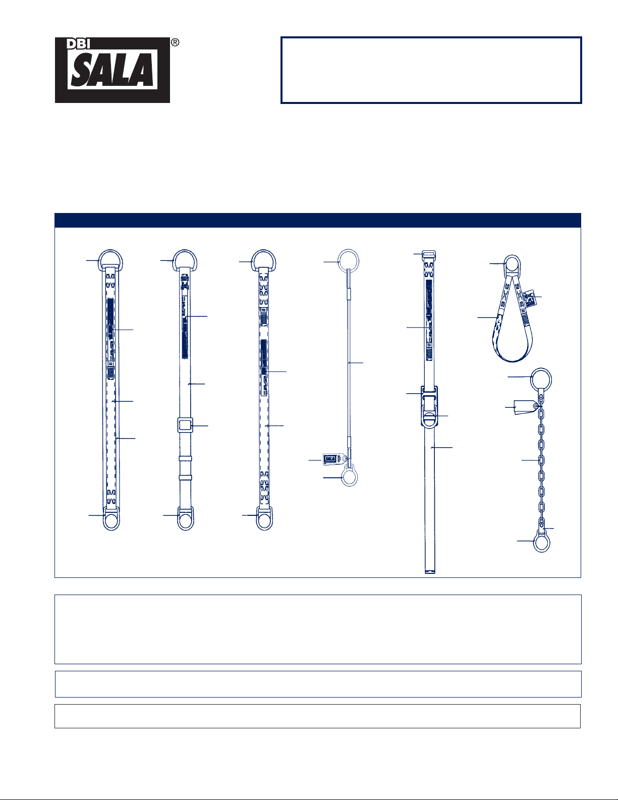
Figure 1 - Tie-off Adapter and Scaffold Choker Anchorage Connectors
Pass-thru
D-ring
Subsystem
Connector
D-ring
Subsystem
Connector
D-ring
Standard
Tie-off Adapter
Pass-thru
D-ring
ID Label
1 3/4 inch
Strength
Member
3 inch
Wear Pad
Adjustable Length
Tie-off Adapter
Pass-thru
D-ring
ID Label
2 inch
Strength
Member
Adjuster
Buckle
Subsystem
Connector
D-ring
ID Label
Kevlar Web
Tie-off Adapter
Pass-thru
O-ring
ID Label
1 3/4 inch
Strength
Member
Small
D-ring
3/8 inch
wire rope
Wire Rope
Tie-off Adapter
Parachute
Buckle
ID Label
Pad
Adjuster
Boom Belt
Subsystem
Connector
D-ring
ID Label
D-ring
1 3/4 inch
Strength
Member
Scaffold Choker
Large
O-ring
Labels
Chain
Small
D-ring
Tie-off Adapter
Connection
Chain
Label
Pivotal
Link
WARNING: This product is part of a personal fall arrest, restraint, work positioning, suspension, or rescue
system. The user must follow the manufacturer's instructions for each component of the system. These
instructions must be provided to the user of this equipment. The user must read and understand these
instructions before using this equipment. Manufacturer's instructions must be followed for proper use and
maintenance of this equipment. Alterations or misuse of this product, or failure to follow instructions, may result
in serious injury or death.
IMPORTANT: If you have questions on the use, care, or suitability of this equipment for your application, contact
DBI-SALA.
IMPORTANT: Record the product identifi cation information from the ID label in the Inspection and Maintenance Log at the back of this of this
manual.
Form: 5902129
Rev: J
1
© Copyright 2013, Capital Safety
Page 2

DESCRIPTION
STANDARD TIE-OFF ADAPTER: Pass through type tie-off adapter, 1-3/4 inch polyester webbing strength
member, 3 inch wide polyester webbing wear pad. Available in various lengths. See Figure 1.
ADJUSTABLE LENGTH TIE-OFF ADAPTER: Pass through type tie-off adapter, 2 inch polyester webbing strength
member with high strength edge for wear protection. Adjustable length. See Figure 1.
KEVLAR WEB TIE-OFF ADAPTER: Pass through type tie-off adapter, 1-3/4 inch Kevlar webbing strength
member. Available in various lengths. See Figure 1.
WIRE ROPE TIE-OFF ADAPTER: Pass through type tie-off adapter, 3/8 inch diameter wire rope. Available in
various lengths. See Figure 1.
BOOM BELT: Parachute buckle type belt, 1-3/4 inch polyester webbing strength member. See Figure 1.
SCAFFOLD CHOKER: Choker type anchorage connector, 1 inch polyester webbing strength member. Available in
various lengths. See Figure 1.
CHAIN TIE-OFF ADAPTER: Pass through type tie-off adapter, zinc-plated stainless steel. See Figure 1.
1.0 APPLICATIONS
1.1 PURPOSE: The tie-off adapter, boom belt, and scaffold choker is designed to be used as an anchorage
connector for a personal fall arrest, restraint, work positioning, suspension, or rescue system. Tie-off
adapters and scaffold chokers may be used as an anchorage connector for a horizontal lifeline if the system
is designed, installed and used under the supervision of a qualifi ed person. Do not hang, lift, or support tools
or equipment from this equipment.
• Kevlar web tie-off adapters should be used when working with high temperature tools or materials, or
in high temperature environments (foundries, chemical manufacturing, steel fabrication, emergency
rescue services, fi re services, welders, oil industry, nuclear industry).
A. PERSONAL FALL ARREST: The anchorage connector is used as a component of a personal fall arrest
system. Personal fall arrest systems typically include a full body harness and a connecting subsystem,
(energy absorbing lanyard). Maximum permissible free fall is 6 feet.
B. RESTRAINT: The anchorage connector is used as a component of a restraint system to prevent the
user from reaching a fall hazard. Restraint systems typically include a full body harness and a lanyard or
restraint line. No vertical free fall permitted.
C. WORK POSITIONING: The anchorage connector is used as a component of a work positioning system
to support the user at a work position. Work positioning systems typically include a full body harness,
positioning lanyard, and a back-up personal fall arrest system. Maximum permissible free fall is 2 feet.
D. PERSONNEL RIDING: The anchorage connector is used as a component of a personnel riding system
to suspend or transport the user vertically. Personnel riding systems typically include a full body
harness, boatswain's chair or seat board, and a back-up personal fall arrest system. No vertical free fall
permitted.
E. RESCUE: The anchorage connector is used as a component of a rescue system. Rescue systems are
configured depending on the type of rescue. No vertical free fall permitted.
1.2 LIMITATIONS: Consider the following application limitations before using this product:
A. CAPACITY: These anchorage connectors are designed for use by persons with a combined weight
(clothing, tools, etc.) of no more than 310 lbs. No more than one personal protective system may be
connected at one time.
B. FREE FALL: Personal fall arrest systems used with this equipment must be rigged to limit the free fall to
6 feet (ANSI Z359.1). See personal fall arrest system manufacturer’s instructions for more information.
Restraint systems must be rigged so that no vertical free fall is possible. Work positioning systems must
be rigged so that free fall is limited to 2 feet or less. Personnel riding systems must be rigged so that no
vertical free fall is possible. Rescue systems must be rigged so that no vertical free fall is possible.
2
Page 3
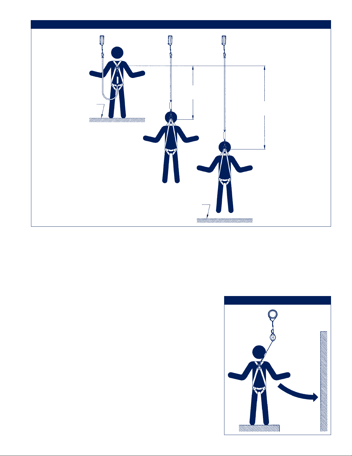
Figure 2 - Fall Clearance
6 Feet Max
Free Fall
Working Level
(Free Fall + Deceleration Distance)
Nearest Obstruction
Total Fall Distance
C. FALL CLEARANCE: See Figure 2. There must be sufficient clearance below the user to arrest a fall
before the user strikes the ground or other obstruction. The clearance required is dependent on the
following factors:
• Elevation of anchorage connector • Connecting subsystem length
• Deceleration distance • Movement of harness attachment element
• Worker height • Free fall distance
See personal fall arrest system manufacturer’s instructions for more information.
D. SWING FALLS: See Figure 3. Swing falls occur when the
anchorage point is not directly above the point where a fall
occurs. The force of striking an object in a swing fall may
cause serious injury or death. Minimize swing falls by working
as close to the anchorage point as possible. Do not permit
a swing fall if injury could occur. Swing falls will significantly
increase the clearance required when a self retracting lifeline
or other variable length connecting subsystem is used.
E. ENVIRONMENTAL HAZARDS: Use of this equipment in
areas with environmental hazards may require additional
precautions to prevent injury to the user or damage to the
equipment. Hazards may include, but are not limited to; heat,
chemicals, corrosive environments, high voltage power lines,
gases, moving machinery, and sharp edges. Contact DBI-SALA
if you have questions about using this equipment where
environmental hazards exist.
F. TRAINING: This equipment must be installed and used
by persons trained in its correct application and use. See
section 4.0.
3
Figure 3 - Swing Falls
Swing Fall Hazard
Page 4
1.3 APPLICABLE STANDARDS: Refer to national standards, including ANSI Z359.1; and local, state, and
federal requirements for more information on personal fall arrest systems and associated components.
2.0 SYSTEM REQUIREMENTS
2.1 COMPATIBILITY OF COMPONENTS: DBI-SALA equipment is designed for use with DBI-SALA approved
components and subsystems only. Substitutions or replacements made with non-approved components
or subsystems may jeopardize compatibility of equipment and may effect the safety and reliability of the
complete system.
2.2 COMPATIBILITY OF CONNECTORS: Connectors are considered to be compatible with connecting
elements when they have been designed to work together in such a way that their sizes and shapes do
not cause their gate mechanisms to inadvertently open regardless of how they become oriented. Contact
DBI-SALA if you have any questions about compatibility.
Connectors ( hooks, carabiners, and D-rings) must be capable of supporting at least 5,000 lbs. (22.2kN).
Connectors must be compatible with the anchorage or other system components. Do not use equipment that
is not compatible. Non-compatible connectors may unintentionally disengage. See Figure 4. Connectors must
be compatible in size, shape, and strength. Self locking snap hooks and carabiners are required by ANSI
Z359.1 and OSHA.
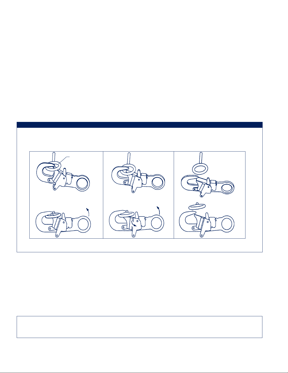
Figure 4 - Unintentional Disengagement (Roll-out)
If the connecting element that a snap hook (shown) or carabiner attaches to is undersized or irregular in shape, a
situation could occur where the connecting element applies a force to the gate of the snap hook or carabiner. This force
may cause the gate (of either a self-locking or a non-locking snap hook) to open, allowing the snap hook or carabiner to
disengage from the connecting point.
Small ring or
other
non-compatibly
shaped element
1. Force is applied to the
snap hook.
2. The gate presses against the
connecting ring.
3. The gate opens allowing the
snap hook to slip off.
2.3 MAKING CONNECTIONS: Only use self-locking snap hooks and carabiners with this equipment. Only use
connectors that are suitable to each application. Ensure all connections are compatible in size, shape and
strength. Do not use equipment that is not compatible. Ensure all connectors are fully closed and locked.
DBI-SALA connectors (snap hooks and carabiners) are designed to be used only as specifi ed in each
product’s user’s instructions. See Figure 5 for inappropriate connections. DBI-SALA snap hooks and
carabiners should not be connected:
A. To a D-ring to which another connector is attached.
B. In a manner that would result in a load on the gate.
NOTE: Large throat opening snap hooks should not be connected to standard size D-rings or similar objects
which will result in a load on the gate if the hook or D-ring twists or rotates. Large throat snap hooks are
designed for use on fi xed structural elements such as rebar or cross members that are not shaped in a way that
can capture the gate of the hook.
4
Page 5
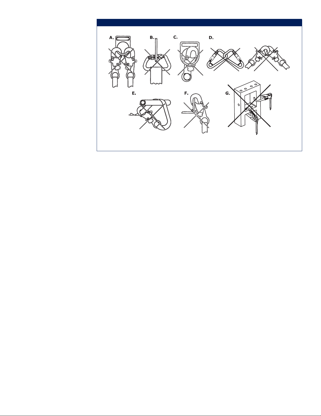
C. In a false
engagement,
where features
that protrude
from the snap
hook or carabiner
catch on the
anchor and
without visual
confirmation
seems to be fully
engaged to the
anchor point.
D. To each other.
E. Directly to
webbing or rope
lanyard or tieback (unless the
manufacturer’s
instructions for
both the lanyard
and connector
specifically allows
such a connection).
Figure 5 - Inappropriate Connections
F. To any object which is shaped or dimensioned such that the snap hook or carabiner will not close and
lock, or that roll-out could occur.
G. In a manner that does not allow the connector to align properly while under load.
2.4 PERSONAL FALL ARREST SYSTEM: Personal fall arrest systems used with this equipment must meet
applicable state, federal, OSHA, and ANSI requirements. A full body harness must be worn when this
equipment is used as a component of a personal fall arrest system. As required by OSHA, the personal fall
arrest system must be capable of arresting the user’s fall with a maximum arresting force of 1,800 lbs., and
limit the free fall to 6 feet or less. If the maximum free fall distance must be exceeded, the employer must
document, based on test data, that the maximum arresting force will not be exceeded, and the personal fall
arrest system will function properly.
When a free fall greater than 6 feet, and up to a maximum of 12 feet is possible, DBI-SALA recommends
using a personal fall arrest system incorporating a DBI-SALA Force2 Energy Absorbing Lanyard. DBI-SALA
has performed testing using the Force2 Energy Absorbing Lanyard in free falls up to 12 feet to ensure the
maximum arresting force does not exceed 1,800 lbs., and the system functions properly. The results of these
tests are listed in the user instruction manual provided with Force2 Energy Absorbing Lanyards.
2.5 ANCHORAGE STRUCTURE: This equipment is intended to be installed on structures capable of meeting the
anchorage strength requirements specifi ed below. The anchorage connector must be of suffi cient length to
wrap completely around the anchorage.
2.6 ANCHORAGE STRENGTH: The anchorage strength required is dependent on the application. Following are
anchorage strength requirements for specifi c applications:
A. FALL ARREST: The structure to which the anchorage connector is attached must sustain static loads
applied in the directions permitted by the fall arrest system of at least: 3,600 lbs. with certification of a
qualified person, or 5,000 lbs. without certification. See ANSI Z359.1 for certification definition. When
more than one personal fall arrest system is attached to an anchorage, the strengths stated above must
be multiplied by the number of personal fall arrest systems attached to the anchorage.
From OSHA 1926.500 and 1910.66: Anchorages used for attachment of a personal fall arrest system
shall be independent of any anchorage being used to support or suspend platforms, and must support at
least 5,000 lbs. per user attached; or be designed, installed, and used as part of a complete personal fall
arrest system which maintains a safety factor of at least two, and is supervised by a qualified person.
5
Page 6

B. RESTRAINT: The structure to which the anchorage connector is attached must sustain static loads
applied in the directions permitted by the restraint system of at least 3,000 lbs. When more than one
restraint system is attached to an anchorage, the strengths stated above must be multiplied by the
number of restraint systems attached to the anchorage.
C. WORK POSITIONING: The structure to which the anchorage connector is attached must sustain
static loads applied in the directions permitted by the work positioning system of at least 3,000 lbs.,
or twice the potential impact load, whichever is greater. When more than one work positioning system
is attached to an anchorage, the strengths stated above must be multiplied by the number of work
positioning systems attached to the anchorage.
D. PERSONNEL RIDING: The structure to which the anchorage connector is attached must sustain static
loads applied in the directions permitted by the personnel riding system of at least 2,500 lbs. When
more than one personnel riding system is attached to an anchorage, the strengths stated above must be
multiplied by the number of personnel riding systems attached to the anchorage.
E. RESCUE: The structure to which the anchorage connector is attached must sustain static loads applied
in the directions permitted by the rescue system of at least 2,500 lbs. When more than one rescue
system is attached to an anchorage, the strengths stated above must be multiplied by the number of
rescue systems attached to the anchorage.
3.0 INSTALLATION AND USE
WARNING: Do not alter or intentionally misuse this equipment; your safety may depend on it. Consult with
DBI-SALA if using this equipment with components or subsystems other than those described in this manual.
Some subsystem and component combinations may interfere with the operation of this equipment.
WARNING: Consult with your doctor if you doubt your fi tness to safely absorb the shock from a fall arrest. Age
and fi tness can seriously affect your ability to withstand falls. Pregnant women and minors must not use this
equipment.
3.1 BEFORE EACH USE of this equipment inspect it according to section 5.0 of this manual.
3.2 PLAN your system before installation. Consider all factors that will affect your safety during use of this
equipment. The following list gives important points to consider when planning your system:
A. ANCHORAGE: Select an anchorage that meets the requirements specified in section 2.0.
B. SHARP EDGES: Avoid working where system components may be in contact with, or abrade against,
unprotected sharp edges. Inspection frequency should be increased when an anchorage connector is
installed around sharp edges.
C. AFTER A FALL: Components which have been subjected to the forces of arresting a fall must be
removed from service and destroyed.
D. RESCUE: The employer must have a rescue plan when using this equipment. The employer must have
the ability to perform a rescue quickly and safely.
3.3 ANCHORAGE CONNECTOR INSTALLATION:
A. ANCHORAGE CONNECTOR LOCATION: Select a location on a suitable strength anchorage that will
provide the best safety to the user.
B. STRUCTURE: The structure to which the anchorage connector is attached must be free of corrosion,
cracks, deformities, or other defects that may weaken the structure. Do not attach an anchorage
connector to a vertical structure unless a means of restraining the connector from sliding down the
structure is present. If the anchorage connector were to slide down the structure in a fall arrest
situation, serious injury to the user is possible. The scaffold choker is designed to attach to round,
smooth structures, such as structural scaffold tubing.
6
Page 7

C. INSTALLING THE TIE-OFF ADAPTER: Place the tie-off adapter over the anchorage with the labels
facing out. The D-rings must be hanging below the anchorage as shown in Figure 6. With the tie-off
adapter positioned on the anchorage, pass the small D-ring through the large D-ring as shown in Figure
7. Slide the large D-ring up to the anchorage, over the webbing attached to the small D-ring. Pull the
small D-ring down to take up slack that was made by moving the large D-ring up. The tie-off adapter
should be tightly wrapped around the anchorage with the small D-ring hanging free as shown in Figure
8. Multiple passes of the tie-off adapter around the anchorage may be made to shorten the length. Pass
the small D-ring through the large D-ring on each pass.
Figure 6
Face labels out
Place tie-off adapter
over anchorage
Figure 7
Pass small D-ring
through large D-ring
D.
Figure 8
Pull tie-off adapter
tight around anchorage
INSTALLING THE CABLE TIE-OFF ADAPTER: Place the tie-off adapter over the anchorage. The
D-rings must be hanging below the anchorage as shown in Figure 9. With the tie-off adapter positioned
on the anchorage, pass the small D-ring through the large O-ring as shown in Figure 10. Slide the large
O-ring up to the anchorage, over the cable attached to the small D-ring. Pull the small D-ring down
to take up slack that was made by moving the large O-ring up. The tie-off adapter should be tightly
wrapped around the anchorage with the small D-ring hanging free as shown in Figure 11. Multiple
passes of the tie-off adapter around the anchorage may be made to shorten the length. Pass the small
D-ring through the large O-ring on each pass.
Figure 9 Figure 10
Place tie-off adapter over
anchorage.
Pass small D-ring through
large O-ring.
7
Figure 11
Pull tie-off
adapter
tight around
anchorage.
Large
O-Ring
Small
D-Ring
Page 8

E. INSTALLING THE CHAIN TIE-OFF ADAPTER: Place the tie-off adapter over the anchorage.
The D-rings must be hanging below the anchorage as shown in Figure 12. With the tie-off adapter
positioned on the anchorage, pass the small D-ring through the large O-ring as shown in Figure 13.
Slide the large O-ring up to the anchorage, over the chain attached to the small D-ring. Pull the small
D-ring down to take up slack that was made by moving the large O-ring up. The tie-off adapter should
be tightly wrapped around the anchorage with the small D-ring hanging free as shown in Figure 14.
Multiple passes of the tie-off adapter around the anchorage may be made to shorten the length. Pass
the small D-ring through the large O-ring on each pass.
Figure 12
Place tie-off adapter
over anchorage.
Figure 13
Pass small D-ring
through large O-ring.
Figure 14
Pull tie-off adapter
tight around
anchorage.
Large
O-Ring
Small
D-Ring
F. INSTALLING THE SCAFFOLD CHOKER: Place the scaffold choker over the anchorage with the labels
facing out. The D-ring must be hanging below the anchorage as shown in Figure 15. Pass the D-ring
under the anchorage and through the web loop as shown in Figure 16. Pull the D-ring down to take up
slack as shown in Figure 17. The scaffold choker should be tightly wrapped around the anchorage.
Figure 15 Figure 16
Face labels out
Figure 17
Place scaffold choker
over anchorage
Pass D-ring through
web loop
8
Pull scaffold choker tight
around anchorage
Page 9

G. INSTALLING THE BOOM BELT: Wrap the belt around the boom
so that the D-ring is on top as shown in Figure 18. Weave end of
web through the parachute buckle (see Figure 19), leave at least
3 inches of web extended past the buckle as shown in Figure
18.
Figure 19
Figure 18
Frame
Minimum of 3 inches of
web through buckle
Knurled bar
Flow of webbing
through the buckle
IMPORTANT: The Boom Belt is to used on structures with smooth
rounded edges only.
WARNING: The anchorage connector must be tight against the
anchoring structure as shown in Figures 8, 11, 14, and 17. Do not
leave slack in the tie-off adapter, this may increase the free fall
distance in the event of a fall. See Figure 20.
3.4 MAKING CONNECTIONS: When using a hook to connect to
the anchorage connector, ensure roll-out cannot occur. Roll-out
occurs when interference between the hook and mating
connector causes the hook gate to unintentionally open and
release. Self locking snap hooks and carabiners should be
used to reduce the possibility of roll-out. Do not use hooks or
connectors that will not completely close over the attachment
object.
Boom
Structure
3 inch web extended
past buckle
Figure 20
Do not leave slack in
anchorage connector
3.5 CONNECTING TO THE ANCHORAGE CONNECTOR: Connect to the installed anchorage connector with
a self locking snap hook or self locking carabiner only. For tie-off adapters, connect your subsystem to the
small D-ring only (do not attach to both D-rings, see Figure 21). Do not use a knot to connect a lifeline to
the anchorage connector. Do not pass lanyard or lifeline through the
Figure 21
anchorage connector D-ring and hook back into lanyard or lifeline.
Ensure connections are fully closed and locked. See Figure 22
for connection of typical fall arrest or restraint equipment to the
anchorage connector. When using an energy absorbing lanyard,
connect the energy absorber "pack" end to the harness. Ensure self
retracting lifeline is positioned so that retraction is not hindered.
Always protect lifeline or lanyard from abrading against sharp or
abrasive surfaces in your work area. Ensure all connections are
compatible in size, shape, and strength. Never connect more than one
personal protective system to a single anchorage connector.
WARNING: The tie-off adapter small D-ring must pass through the large
Do not attach
subsystem to
both D-rings on
tie-off adapter
D-ring. The connecting subsystem must be connected to the small D-ring
only. Do not attach the subsystem to both D-rings. See Figure 21.
9
Page 10

Anchorage
Figure 22 - Connecting to the Anchorage Connector
Tie-off
Adapter
Anchorage
Tie-off
Adapter
Connector
Anchorage
Tie-off
Adapter
SRL
S/A Lanyard
Rope Grab
Rope
Lanyard
S/A Lanyard
4.0 TRAINING
4.1 It is the responsibility of the user to assure they are familiar with these instructions, and are trained in the
correct care and use of this equipment. User must also be aware of the operating characteristics, application
limits, and the consequences of improper use of this equipment.
IMPORTANT: Training must be conducted without exposing the trainee to a fall hazard. Training should be
repeated on a periodic basis.
5.0 INSPECTION
5.1 FREQUENCY:
• Before each use inspect the tie-off adaptor according to sections 5.2 and 5.3.
• Formal Inspection: A formal inspection of the anchorage connector must be performed at least
annually by a competent other than the user. The frequency of formal inspections should be based
on conditions of use or exposure. See sections 5.2 and 5.3. Record the inspection results in the
Inspection and Maintenance Log at the back of this manual.
IMPORTANT: If this equipment has been subjected to fall arrest forces it must be immediately removed from
service and destroyed.
5.2 INSPECTION STEPS:
Step 1. Inspect the anchorage connector hardware, including, chain, pivotal link, D-rings, O-ring, cable,
thimble, ferrules, rivets, and adjuster buckle. These items must not be damaged, broken, distorted
or have any sharp edges, burrs, cracks, worn parts, or corrosion.
Step 2. Webbing: Inspect the anchorage connector webbing and stitching. The webbing must be free of
frayed, cut or broken fi bers. Check for tears, abrasions, mold, or discoloration. The webbing must be
free of knots, excessive soiling, heavy paint build-up, and rust staining. Check for chemical or heat
damage, indicated by brown, discolored, or brittle areas. Check for ultraviolet degradation, indicated
by discoloration and the presence of splinters or slivers on the webbing surface. Check for pulled or
cut stitches. Broken stitches may be an indication that the anchorage connector has been impact
loaded and must be removed from service. All the above factors are known to reduce the strength
of the anchorage connector. Damaged or questionable anchorage connectors must be removed from
service.
10
Page 11

Wire Rope: Inspect the wire rope for cuts, kinks, broken wires, bird-caging, corrosion, welding
splatter, chemical contact areas, rust, corrosion, broken wires, severely abraded areas or other
obvious faults. Inspect thimbles for cracks or damage.
Step 3. Ensure the condition of the anchorage will support the anchorage connector loads. See section 2.6.
An anchorage connector connected to a damaged anchorage must not be used.
Step 4. Ensure the anchorage connector is securely attached to the anchoring structure. If anchorage
connector is loose, do not use. Reconnect the anchorage connector to the anchorage according to
section 3.3.
Step 5. Inspect each system component or subsystem according to associated manufacturer's instructions.
Step 6. Record the inspection date and results in the Inspection and Maintenance Log.
5.3 If inspection reveals an unsafe or defective condition, remove anchorage connector from service and
destroy.
IMPORTANT: Only DBI-SALA or parties authorized in writing may make repairs to this equipment.
6.0 MAINTENANCE, STORAGE
6.1 Clean anchorage connector with water and a mild detergent solution. Wipe off hardware with a clean, dry
cloth and hang to air dry. Do not force dry with heat. An excessive build-up of dirt, paint, etc. may prevent
the anchorage connector from working properly, and may degrade the webbing to a point where it has
become weakened and should be removed from service. If you have questions concerning the condition of
your anchorage connector, or have any doubt about putting it into service, contact DBI-SALA.
6.2 Store the anchorage connector in a cool, dry, clean environment, out of direct sunlight. Avoid areas where
chemical vapors exist. Thoroughly inspect the anchorage connector after extended storage.
7.0 SPECIFICATIONS
Standard Tie-Off Adapter:
Hardware: Forged alloy steel D-rings.
Webbing: 1-3/4 inch polyester strength member, 3 inch polyester wear pad.
MINIMUM BREAKING STRENGTH: 5,000 lbs. when loaded within the recommended working range.
CAPACITY: 310 lbs. (one person)
Meets ANSI Z359.1 and OSHA requirements.
Adjustable Tie-Off Adapter:
HARDWARE: Forged alloy steel D-rings, alloy steel adjuster buckle.
WEBBING: 2 inch polyester strength member with high strength edge.
MINIMUM BREAKING STRENGTH: 5,000 lbs. when loaded within the recommended working range.
CAPACITY: 310 lbs. (one person)
Meets ANSI Z359.1 and OSHA requirements.
Kevlar Web Tie-off Adapter:
Hardware: Forged alloy steel D-rings.
Webbing: 1-3/4 inch Kevlar strength member.
Minimum Breaking Strength: 5,000 lbs. when loaded within the recommended working range.
Capacity: 310 lbs. (one person)
Meets OSHA requirements.
Wire Rope Tie-off Adapter:
Hardware: Zinc Plated Steel, Stainless Steel.
Cable: wire rope, 3/8 inch diameter, 7x9 strand, 302 or 304 stainless steel, breaking strength of
12,000 lbs min.
Minimum Breaking Strength: 5,000 lbs. when loaded within the recommended working range.
Capacity: 310 lbs. (one person)
Meets ANSI Z359.1 and OSHA requirements.
11
Page 12

Boom Belt:
Hardware: Forged alloy steel D-ring.
Webbing: 1-3/4 inch polyester strength member.
Minimum Breaking Strength: 5,000 lbs. when loaded within the recommended working range.
Capacity: 310 lbs. (one person)
Meets ANSI Z359.1 and OSHA requirements.
Chain Tie-off Adapter:
HARDWARE: Zinc-plated Steel, Stainless Steel
MINIMUM BREAKING STRENGTH: 5,000 lbs. when loaded within the recommended working range.
CAPACITY: 310 lbs. (one person)
Meets ANSI Z359.1 and OSHA requirements
Scaffold Choker:
Hardware: Forged alloy steel D-rings.
Webbing: 1 inch polyester strength member
Minimum Breaking Strength: 5,000 lbs. when loaded within the recommended working range.
Capacity: 310 lbs. (one person)
Meets ANSI Z359.1 and OSHA requirements.
12
Page 13

8.0 LABELING
8.1 These labels must be securely attached to the anchorage connector and fully legible. See Figure 1 for label
locations.
ID Label, Standard, Adjustable Length Tie-off Adapters, and Boom Belt
ID Label, Kevlar Web Tie-off Adapters
Wire Rope and Chain Tie-off Adapter Label Part 1
Wire Rope and Chain Tie-off Adapter Label Part 2
Wrap the web loop
over the structural
member and pull
the D-ring through
the loop as shown.
Connect the
personal fall arrest
or restraint system
to the D-ring.
Loop and D-ring Label, Scaffold Choker Only
13
Page 14

This instruction applies to the following models:
1001250
1001251
1002001
1002002
1002004
1002005
1002007
1002008
1002009
1002010
1002011
1002012
1002013
1002014
1002015
1002016
1002017
1002018
1002019
1002020
1002021
1002022
1002023
1002024
1002025
1002026
1002027
1002028
1002029
1002030
1002033
1002035
1002036
1002038
1002040
1002041
1002042
1002043
1002044
1002045
1002046
1002051
1002053
1002054
1002055
1002056
1002103
1002104
1002105
1002106
1002108
1002110
1002112
1002115
1002116
1002120
1002130
1002140
1002141
1002200
1002201
1002202
1002203
1002204
1002205
1002206
1002207
1002300
1002325
1003000
1003000ALT
1003006
1003006ALT
1003100
1003105
1003200
1003201
1003202
1003203
1003204
1003205
1003206
1003207
1003208
1003209
1003525
1003526
1105925
1105975
1160000
1160000
1160002
1160002
1160004
1160004
1160005
1160005
1160006
1160006
1160007
1160007
1170000
1170000
1170001C
1170001C
1170002
1170002
1170002
1170002
1170003
1170003
1170003
1170003
1201390
1201391
1201392
1201393
1201394
1201395
1201396
1201397
1201398
1201399
1201420
1201421
1201422
1201423
2104519
2104519
2104520
2104520
2104520
2104520
2104525
2104525
2104527
2104527
2104528
2104528
2104530
2104530
2104531
2104531
3303040
3321000
3321000
3321001
3321001
3321002
3321002
3321003
3321003
3321004
3321004
3321005
3321005
3321006
3321006
3321007
3321007
3321009
3321009
3321985
3321985
3321986
3321986
3321987
3321987
3321988
3321988
3321989
3321989
3321994
3321994
3321995
3321995
3321996
3321996
3321997
3321997
3321998
3321998
3400650
3400651
3400652
3400653
3400654
3400655
3400656
3400657
3400658
3400660
3400661
3400860
3400860B
3400861
3400862
3400862B
3400863
3400864
3400865
3400870
3400871
3400872
3400873
3400874
3400874B
3400875
3400876
3400877
3400878
3400879
3400882
3400883
3400885
3400885B
3400886
3400886B
3400887
3400888
3400889
3400890
3400900
3400900B
3400900C
3400901
3400901C
3400902
3400902B
3400902C
3400903
3400910
3400911
3400912
3400912B
3400913
3400914
3400915
3400920
3400920C
3400921
3400921C
3400922
3400922B
3400922C
3400923
3400923C
3400924
3400924C
3400925
3400926
3400926C
3400930
3400930B
3400930C
3400931
3400931C
3400932
3400932B
3400932C
3400940
3400940C
3400941
3400941C
3400942
3400942B
3400942C
3400965
3400965B
3400966
3400967
3400967B
3400968
3400969
3400970
3400975
3400976
3400977
3400978
3400979
3400979B
3400980
3400981
3400982
3400983
3400984
3400987
3400988
3400990
3400990B
3400991
3400991B
3400992
3400993
3400994
3400995
3401002
3401003
3401004
3401004B
3401005
3401006
3401007
3600000
3600000
5000400
5000400
5000401
5000401
5000402
5000402
5003010
5003010
5003020
5003020
5003025
5003025
5003030
5003030
5003040C
5003040C
5003045
5003045
5003050
5003050
5003050C
5003050C
5003060
5003060
5003070
5003070
5003080
5003080
5003085
5003085
5003100
5003100
5003100C
5003100C
5003120
5003120
5003125
5003125
5003130
5003130
5003150
5003150
5003150C
5003150C
5003155C
5003155C
5003165
5003165
5003175
5003175
5003200
5003200
5003250
5003250
5003300
5003300
5003350
5003350
5900500
5900550
5900551
5900552
5900553
5900554
5900555
5900556
5900557
5900558
5900559
5900560
5900561
5900562
5900563
5900564
5900565
5900566
5900567
5900568
5900569
5900570
5900571
5900572
5900573
5900574
5900700
5900701
5900702
5900703
5900704
5900705
5900706
7600008
7600008
7600009
7600009
7600010
7600020
7600030
7600031
7600040
7600050
7600060
7600070
7600080
7600090
7600100
7600209
7600210
7600211
7600211
7600502
7600502
7600503
7600503
7600504
7600504
7600505
7600505
7600506
7600506
7600507
7600507
7600508
7600508
7600509
7600509
7600510
7600510
7600513
7600513
7600515
7600516
7600518
Additional model numbers may appear on the next printing of these instructions.
Page 15

INSPECTION AND MAINTENANCE LOG
SERIAL NUMBER:
MODEL NUMBER:
DATE PURCHASED: DATE OF FIRST USE:
INSPECTION DATE INSPECTION ITEMS
NOTED
Approved By:
Approved By:
Approved By:
Approved By:
Approved By:
Approved By:
Approved By:
Approved By:
CORRECTIVE ACTION MAINTENANCE
PERFORMED
Approved By:
Approved By:
Approved By:
Approved By:
Approved By:
Approved By:
Approved By:
Approved By:
Approved By:
Approved By:
Page 16

LIMITED LIFETIME WARRANTY
Warranty to End User: D B Industries, Inc., dba CAPITAL SAFETY USA (“CAPITAL SAFETY”) warrants to the
original end user (“End User”) that its products are free from defects in materials and workmanship under
normal use and service. This warranty extends for the lifetime of the product from the date the product is
purchased by the End User, in new and unused condition, from a CAPITAL SAFETY authorized distributor.
CAPITAL SAFETY’S entire liability to End User and End User’s exclusive remedy under this warranty is limited
to the repair or replacement in kind of any defective product within its lifetime (as CAPITAL SAFETY in its sole
discretion determines and deems appropriate). No oral or written information or advice given by CAPITAL
SAFETY, its distributors, directors, offi cers, agents or employees shall create any different or additional
warranties or in any way increase the scope of this warranty. CAPITAL SAFETY will not accept liability for defects
that are the result of product abuse, misuse, alteration or modifi cation, or for defects that are due to a failure to
install, maintain, or use the product in accordance with the manufacturer’s instructions.
CAPITAL SAFETY’S WARRANTY APPLIES ONLY TO THE END USER. THIS WARRANTY IS THE ONLY WARRANTY
APPLICABLE TO OUR PRODUCTS AND IS IN LIEU OF ALL OTHER WARRANTIES AND LIABILITIES, EXPRESSED
OR IMPLIED. CAPITAL SAFETY EXPRESSLY EXCLUDES AND DISCLAIMS ANY IMPLIED WARRANTIES OF
MERCHANTABILITY OR FITNESS FOR A PARTICULAR PURPOSE, AND SHALL NOT BE LIABLE FOR INCIDENTAL,
PUNITIVE OR CONSEQUENTIAL DAMAGES OF ANY NATURE, INCLUDING WITHOUT LIMITATION, LOST PROFITS,
REVENUES, OR PRODUCTIVITY, OR FOR BODILY INJURY OR DEATH OR LOSS OR DAMAGE TO PROPERTY, UNDER
ANY THEORY OF LIABILITY, INCLUDING WITHOUT LIMITATION, CONTRACT, WARRANTY, STRICT LIABILITY, TORT
(INCLUDING NEGLIGENCE) OR OTHER LEGAL OR EQUITABLE THEORY.
CSG USA & Latin America
3833 SALA Way
Red Wing, MN 55066-5005
Toll Free: 800.328.6146
Phone: 651.388.8282
Fax: 651.388.5065
solutions@capitalsafety.com
CSG EMEA
(Europe, Middle East, Africa)
Le Broc Center
Z.I. 1ère Avenue
5600 M B.P. 15 06511
Carros
Le Broc Cedex
France
Phone: + 33 4 97 10 00 10
Fax: + 33 4 93 08 79 70
information@capitalsafety.com
The Ultimate in Fall Protection
CSG Canada
260 Export Boulevard
Mississauga, ON L5S 1Y9
Phone: 905.795.9333
Toll-Free: 800.387.7484
Fax: 888.387.7484
info.ca@capitalsafety.com
CSG Australia & New Zealand
95 Derby Street
Silverwater
Sydney NSW 2128
AUSTRALIA
Phone: +(61) 2 8753 7600
Toll-Free : 1 800 245 002 (AUS)
Toll-Free : 0800 212 505 (NZ)
Fax: +(61) 2 87853 7603
sales@capitalsafety.com.au
www.capitalsafety.com
CSG Northern Europe
5a Merse Road
North Moons, Moat
Reditch, Worcestershire, UK
B98 9HL
Phone: + 44 (0)1527 548 000
Fax: + 44 (0)1527 591 000
csgne@capitalsafety.com
CSG Asia
Singapore:
16S, Enterprise Road
Singapore 627666
Phone: +65 - 65587758
Fax: +65 - 65587058
inquiry@capitalsafety.com
Shanghai:
Rm 1406, China Venturetech Plaza
819 Nan Jing Xi Rd,
Shanghai 200041, P R China
Phone: +86 21 62539050
Fax: +86 21 62539060
ISO
9001
 Loading...