

Page 1
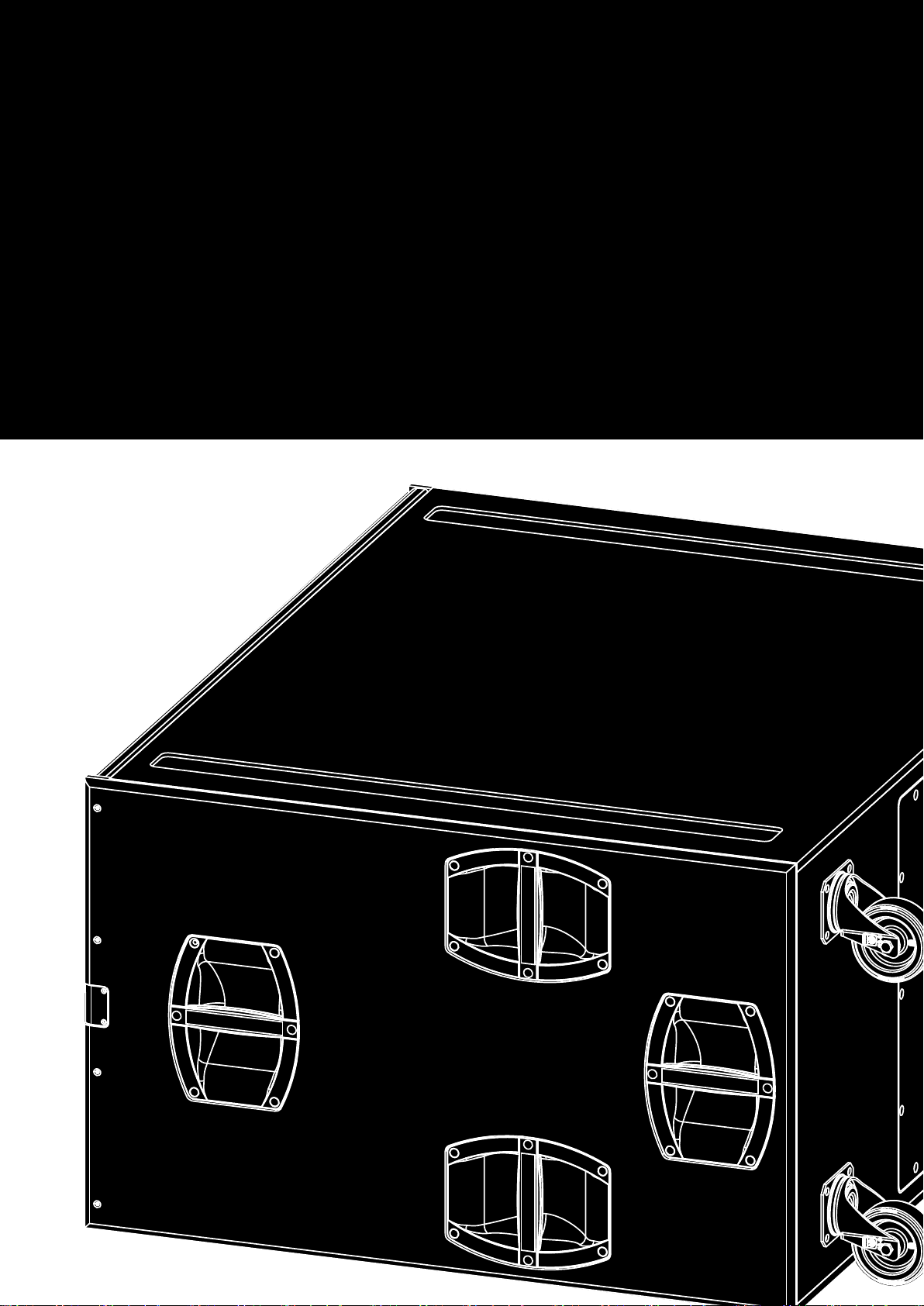
B22-SUB
B
Manual 1.2 en
Page 2

General information
B22-SUB Manual
Version: 1.2 en, 11/2018, D2729.EN .01
Copyright © 2018 by d&b audiotechnik GmbH; all rights
reserved.
Keep this document with the product or in a safe place
so that it is available for future reference.
We recommend you to regularly check the d&b website for the
latest version of this document.
When reselling this product, hand over this document to the new
owner.
If you supply d&b products, please draw the attention of your
customers to this document. Enclose the relevant documents with
the systems. If you require additional documents for this purpose,
you can order them from d&b.
d&b audiotechnik GmbH
Eugen-Adolff-Straße 134, D-71522 Backnang, Germany
T +49-7191-9669-0, F +49-7191-95 00 00
Page 3

Contents
1 Safety precautions.............................................................. 4
1.1 Information regarding the use of loudspeakers........................ 4
2 B22-SUB loudspeaker........................................................ 5
2.1 Product description..................................................................... 5
2.2 Connections................................................................................ 5
2.3 Operation.................................................................................... 6
2.3.1 Controller settings.................................................................... 7
2.4 Technical specifications.............................................................. 7
3 Manufacturer's declarations........................................... 9
3.1 EU conformity of loudspeakers (CE symbol)............................ 9
3.1.1 WEEE Declaration (Disposal)................................................. 9
d&b B22-SUB Manual 1.2 en 3
Page 4

1 Safety precautions
1.1 Information regarding the use of loudspeakers
Potential risk of personal injury
Never stand in the immediate vicinity of loudspeakers driven at a
high level. Professional loudspeaker systems are capable of
causing a sound pressure level detrimental to human health.
Seemingly non-critical sound levels (from approx. 95 dB SPL) can
cause hearing damage if people are exposed to it over a long
period.
In order to prevent accidents when deploying loudspeakers on the
ground or when flown, please take note of the following:
▪ When setting up the loudspeakers or loudspeaker stands, make
sure they are standing on a firm surface. If you place several
systems on top of one another, use straps to secure them
against movement.
▪ Only use accessories which have been tested and approved by
d&b for assembly and mobile deployment. Pay attention to the
correct application and maximum load capacity of the
accessories as detailed in our specific "Mounting instructions" or
in our "Flying system and Rigging manuals".
▪ Ensure that all additional hardware, fixings and fasteners used
for installation or mobile deployment are of an appropriate size
and load safety factor. Pay attention to the manufacturers'
instructions and to the relevant safety guidelines.
▪ Regularly check the loudspeaker housings and accessories for
visible signs of wear and tear, and replace them when
necessary.
▪ Regularly check all load bearing bolts in the mounting devices.
Potential risk of material damage
Loudspeakers produce a static magnetic field even if they are not
connected or are not in use. Therefore make sure when erecting
and transporting loudspeakers that they are nowhere near
equipment and objects which may be impaired or damaged by an
external magnetic field. Generally speaking, a distance of 0.5 m
(1.5 ft) from magnetic data carriers (floppy disks, audio and video
tapes, bank cards, etc.) is sufficient; a distance of more than 1 m
(3 ft) may be necessary with computer and video monitors.
d&b B22-SUB Manual 1.2 en4
Page 5
2 B22-SUB loudspeaker
2.1 Product description
The B22-SUB is an actively driven subwoofer housing a pair of 18"
long excursion neodymium LF drivers built into a bandpass horn
cabinet. Its frequency response extends from 32 Hz to 90 Hz.
The cabinet is constructed from marine plywood and has an impact
resistant paint finish. The front of the loudspeaker cabinet is
protected by a rigid metal grill backed by an acoustically
transparent foam. Each side panel incorporates four handles and
mounted on the rear panel are four heavy duty wheels. The
enclosure features two runners recessed in the bottom panel to
protect the bottom panel from scratching. Two correspondingly
shaped recesses are incorporated into the top panel of each
B22-SUB cabinet to accept these runners, preventing cabinet
movement when stacked.
2.2 Connections
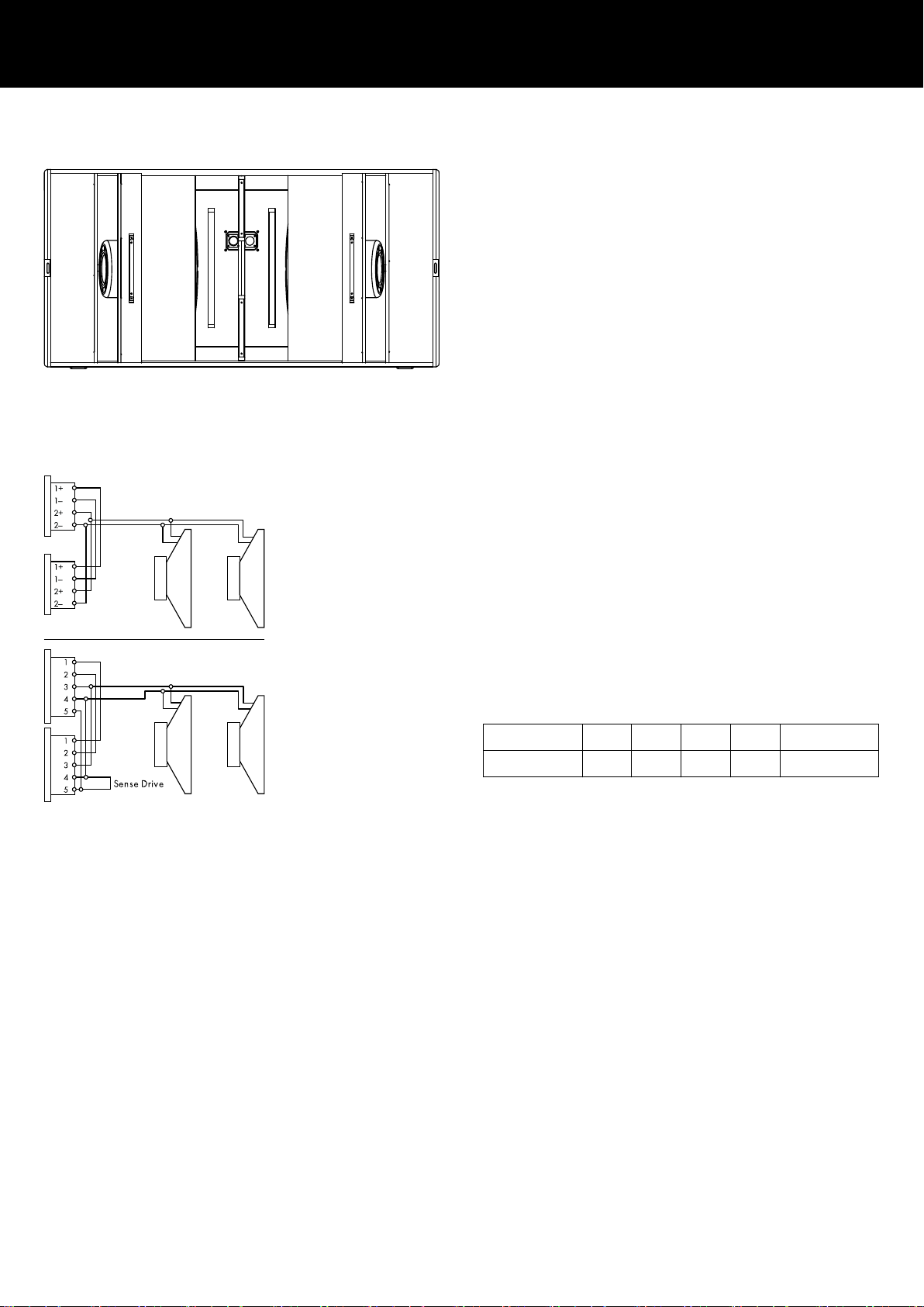
The cabinet is fitted with NLT4 F/M connectors. All four pins of
both connectors are wired in parallel. The B22-SUB uses the pin
assignments 2+/2–. Pins 1+/1– are designated to TOP cabinets.
In Mix TOP/SUB mode, when one connector is used as the input,
the second connector allows for direct connection (link) to a TOP
cabinet.
NLT4 F/M and EP5 connector wiring
Note: Only one B22-SUB may be connected. The second
connector socket must not be used to link another B22-SUB
cabinet.
The cabinet can be supplied with EP5 connectors as an option.
Pin equivalents of the connector options are listed in the table
below.
NLT4 F/M
1+ 1– 2+ 2– n.a.
EP5 1 2 3 4 5 (SenseDrive)
d&b SenseDrive
The SenseDrive feature within D12 amplifiers enables electrical
compensation for the properties of the loudspeaker cable used.
SenseDrive requires an additional sense wire. SenseDrive is
therefore only available with EP5 connectors and 5-wire cabling
for applicable loudspeakers.
Note: When the D12 is operated in "Mix TOP/SUB mode",
the SenseDrive function is only available at the output B
connector.
d&b LoadMatch
Starting with the D80 amplifier platform, the LoadMatch function
enables the amplifier to electrically compensate for the properties
of the loudspeaker cable used without the need for an additional
sense wire. For applicable loudspeakers, LoadMatch is therefore
independent of the connector type used.
d&b B22-SUB Manual 1.2 en 5
Page 6
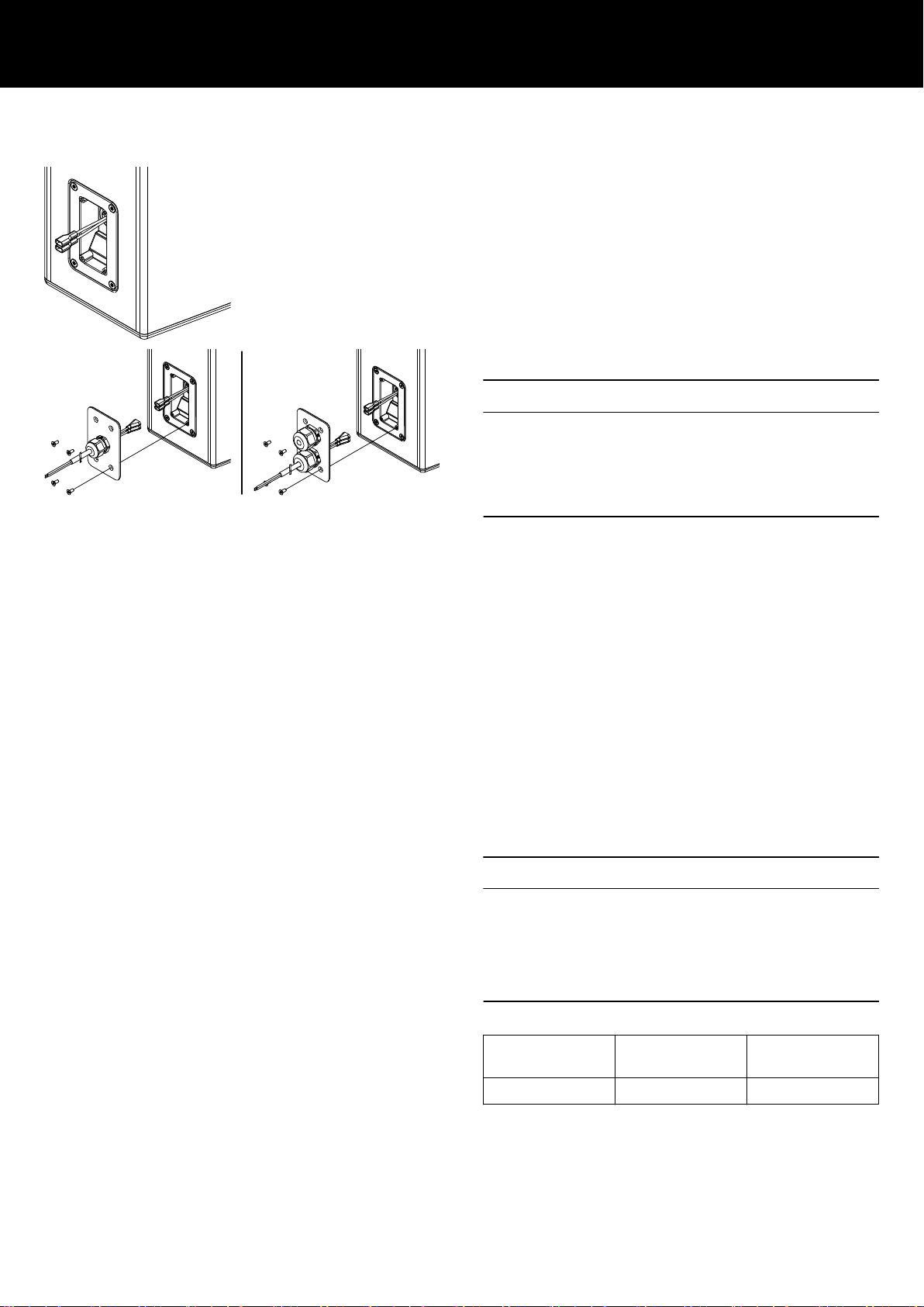
Faston type connector, male single PG (standard), dual PG
(optional)
WR option (Weather Resistance)
A number of d&b loudspeakers are available in special options
suitable for different types of installed applications and
environmental conditions. The following options are available for
the B22-SUB loudspeaker:
▪ Sea water resistant (SWR): This option is suitable for outdoor
use, especially in wet and acid or salty environments.
WR cabinets are equipped with a recessed connector panel
including a Faston type connector (2 x 6.3 mm, female). A cover
plate which accepts single or dual PG cable glands (Type PG13.5
for cable diameters from 6 - 12 mm) is enclosed, as shown in the
graphic opposite.
NOTICE!
The WR option enables operation of loudspeakers in changing
ambient conditions, however it is not intended to enable
permanent, unprotected operation of loudspeakers outdoors.
▪ Provide an additional cover over the loudspeakers.
▪ Aim the cabinets either horizontally or with a downward tilt.
To install the fixed connection cable, please proceed as follows:
Tools required: Screw driver (#T20).
Note: Observe the correct polarity of the cable
Brown (+) / Blue (—).
1. Insert the connection cable through the PG screwing and
connect the male connector to the female connector.
2. Push the cover plate towards the connector panel until it fits
into place.
3. Fix the cover plate to the connector panel using the four
countersunk screws.
2.3 Operation
NOTICE!
Only operate d&b loudspeakers with a correctly configured d&b
amplifier, otherwise there is a risk of damaging the loudspeaker
components.
Applicable d&b amplifiers:
D80/D20/D12/30D.
Application Setup Cabinets per
channel
B22-SUB B22-SUB 1
Within applicable d&b amplifiers, the controller setup is available
in Dual Channel or Mix TOP/SUB mode.
d&b B22-SUB Manual 1.2 en6
Page 7
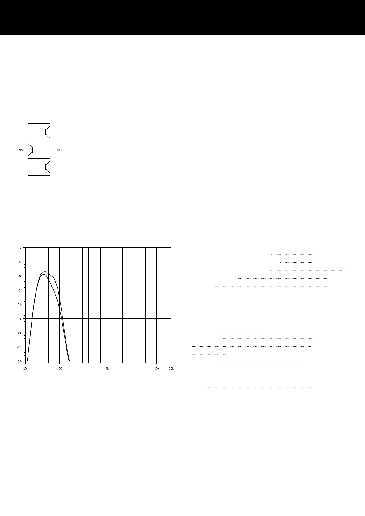
CSA Stack (example)
2.3.1 Controller settings
For acoustic adjustment the INFRA and CSA function can be
selected.
INFRA circuit
Selecting the INFRA circuit restricts the frequency response to a
narrow 32 Hz – 68 Hz range (–5 dB). This transforms the
B22-SUB into an infrabass system.
CSA mode
The CSA (Cardioid Subwoofer Array) mode enables the
combination of three or multiples of three subwoofer cabinets into
an array which produces exceptional low frequency directivity
control.
The amplifier channel for the center subwoofer of the array, which
is physically pointed to the rear, has CSA selected. The forward
facing cabinets are driven with an amplifier channel set to
standard mode. The resulting cardioid behavior of the array will
significantly reduce the energy radiated to the rear.
For further information, please refer to the d&b TI 330 Cardioid
Subwoofer Array, which is available for download at
www.dbaudio.com.
B22-SUB frequency response, standard and INFRA modes
2.4 Technical specifications
System data
Frequency response (–5 dB standard)
Frequency response (–5 dB INFRA mode) 32 Hz - 68 Hz
Max. sound pressure (1 m, free field)
with D12/D20/30D 140 dB
with D80 143 dB
(SPLmax peak, pink noise test signal with crest factor of 4)
37 Hz - 90 Hz
Loudspeaker data
Nominal impedance
Power handling capacity (RMS/peak 10 ms) 1000/4000 W
Components 2 x 18" driver with neodymium magnet
Connections 2 x NLT4 F/M
optional 2 x EP5
WR option: Faston type connector (2 x 6.3 mm), female
Pin assignment NLT4 F/M: 2+/2–
WR option: Brown: (+) / Blue: (–)
Weight 106 kg (234 lb)
4 ohms
EP5: 3:+ / 4:–
d&b B22-SUB Manual 1.2 en 7
Page 8
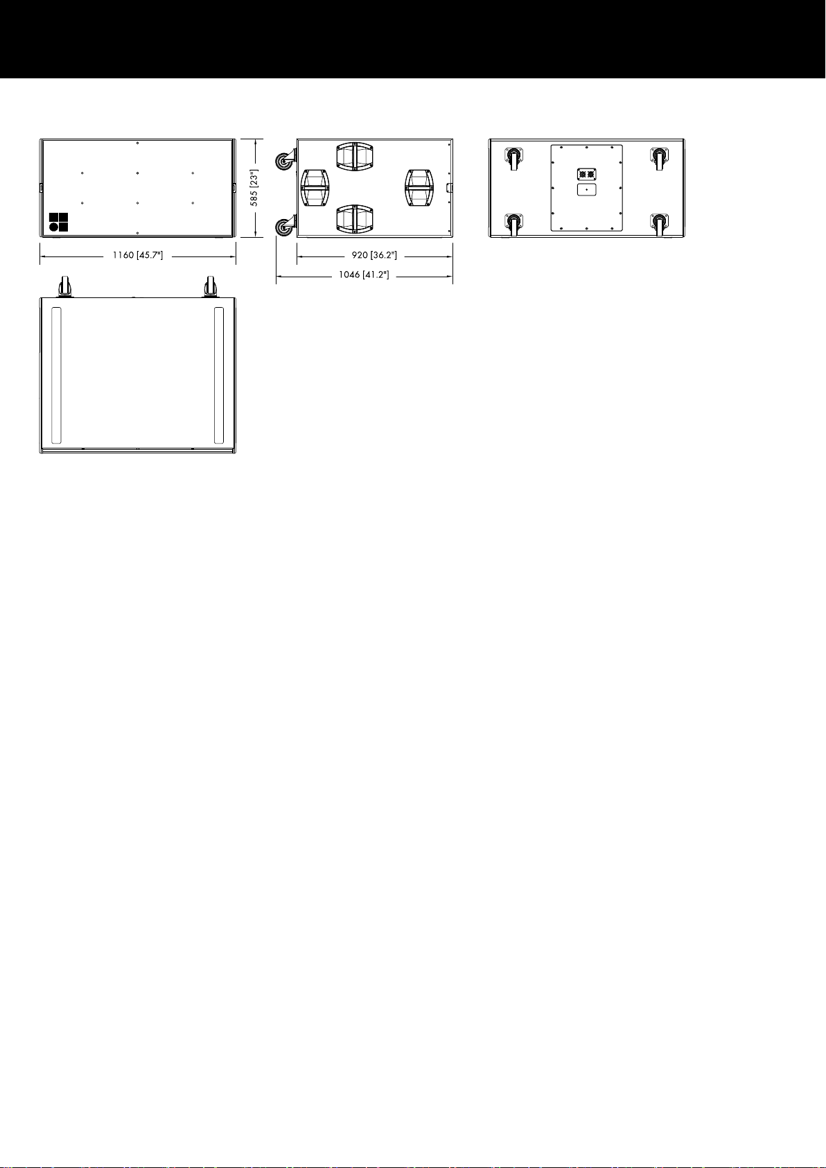
B22-SUB cabinet dimensions in mm [inch]
d&b B22-SUB Manual 1.2 en8
Page 9

3 Manufacturer's declarations
3.1 EU conformity of loudspeakers (CE symbol)
This declaration applies to:
d&b B22-SUB loudspeaker, Z0057
manufactured by d&b audiotechnik GmbH.
All production versions of these types are included, provided they
correspond to the original technical version and have not been
subject to any later design or electromechanical modifications.
We herewith declare that said products are in conformity with the
provisions of the respective EC directives including all applicable
amendments.
A detailed declaration is available on request and can be ordered
from d&b or downloaded from the d&b website at
www.dbaudio.com.
3.1.1 WEEE Declaration (Disposal)
Electrical and electronic equipment must be disposed of separately
from normal waste at the end of its operational lifetime.
Please dispose of this product according to the respective national
regulations or contractual agreements. If there are any further
questions concerning the disposal of this product, please contact
d&b audiotechnik.
d&b B22-SUB Manual 1.2 en 9
Page 10

Page 11

D2729.EN .01, 11/2018 © d&b audiotechnik GmbH
www.dbaudio.com
 Loading...