

Page 1

J-Series Rigging manual (1.3 EN)
Page 2
WARNING!
References in the manual
This refers to a potentially dangerous situation which
may lead to personal injury.
CAUTION!
IMPORTANT!
Note:
This refers to a potentially dangerous situation which
may lead to damage to the equipment.
This refers to a situation which may cause the equipment
to malfunction.
Additional information and/or references.
Symbols on the equipment
Please refer to the information in the operating manual.
General Information
J-Series
Rigging manual
Version 1.3 EN, 05/2012, D2983.EN .01
Copyright © 2012 by d&b audiotechnik GmbH; all rights reserved.
Keep this manual with the product or in a safe place so that it is
available for future reference.
When reselling this product, hand over this manual to the new
customer.
If you supply d&b products, please draw the attention of your
customers to this manual. Enclose the relevant manuals with the
systems. If you require additional manuals for this purpose, you can
order them from d&b.
d&b audiotechnik GmbH
Eugen-Adolff-Strasse 134, D-71522 Backnang, Germany
Telephone +49-7191-9669-0, Fax +49-7191-95 00 00
E-mail: docadmin@dbaudio.com, Internet: www.dbaudio.com
Page 3

Contents
1. Safety precautions...........................................................4
1.1. Intended use...............................................................................................4
1.2. Load capacity/System safety.................................................................4
1.2.1. ArrayCalc / TI 385.......................................................................4
1.3. Operational safety....................................................................................5
2. J-Series rigging concept..................................................6
2.1. Z5300 J Flying frame...............................................................................6
2.1.1. System components overview...................................................7
2.1.2. Z5300 J Flying frame center bar..............................................8
2.1.3. Z5300 J Flying frame dimensions.............................................9
2.1.4. Dimensions of the Mounting plate [1.3]..................................9
2.1.5. Z5303 J Safety chain................................................................10
Z5303 Specifications.................................................................10
2.2. Optional components............................................................................10
2.2.1. Z5305 J Hoist connector chain...............................................10
Z5305 Specifications.................................................................10
2.2.2. E7441 Touring case 1 x Z5300 J Flying frame.................10
3. Preparation....................................................................11
3.1. General preparations............................................................................11
3.2. Inspections................................................................................................11
3.3. J-Series Locking pins..............................................................................11
3.4. Splay link position at the Z5300 J Flying frame............................12
3.5. Suspension of the Z5300 J Flying frame.........................................13
3.5.1. J Load adapter............................................................................13
3.5.2. Single hoist set up.......................................................................14
3.5.3. Dual hoist set up.........................................................................14
3.6. Secondary safety....................................................................................15
3.6.1. Secondary safety at the Z5300 J Flying frame.................15
3.7. Horizontal aiming and securing of the array against rotation..16
4. J-Series arrays and assembly......................................17
4.1. Variant 1: J8/J12 Array.......................................................................18
4.1.1. Preparations and order of assembly.....................................18
4.1.2. Derigging......................................................................................21
4.2. Variant 2: J-SUB and J8/J12 Arrays................................................22
4.2.1. Preparations and order of assembly.....................................22
4.2.2. Derigging......................................................................................26
4.3. Variant 3: J-SUB Array.........................................................................26
4.4. Variant 4: J-Series ground stacks......................................................26
4.4.1. Limitations for J-Series Ground stacks..................................26
4.4.2. Preparations.................................................................................26
4.4.3. J8/J12 ground stack assembly...............................................27
4.5. Ground stack with J-SUB and J8/J12..............................................29
4.5.1. J-SUB stacks.................................................................................29
5. Wind loads.....................................................................30
6. Care and maintenance / Disposal................................31
6.1. Transport / Storing................................................................................31
6.2. Visual and functional inspection.........................................................31
6.3. Disposal.....................................................................................................31
EC Declaration of Conformity............................................32
J-Series Rigging manual (1.3 EN) Contents - 1
Page 4
1. Safety precautions
1.1. Intended use
The J-Series rigging components (Flying frame, Load adapter, Locking
pins) must only be used in conjunction with the d&b J-Series
loudspeakers J8, J12 and J-SUB as described in this manual.
Installation and set up should only be carried out by qualified and
authorized personnel observing the valid national Rules of Prevention of
Accident (RPA).
It is the responsibility of the person installing the assembly to ensure that
the suspension/fixing points are suitable for the intended use.
1.2. Load capacity/System safety
The Z5300 J Flying frame is designed to suspend a total
system weight of 1.5 t (3300 lb) WLL (Working Load
Limit) according to BGV C1.
The rigging components allow arrays of up to 10 x J-TOP cabinets
(J8/J12) or a total system weight of 665 kg (1466 lb) to be flown in any
vertical splay angle configuration.
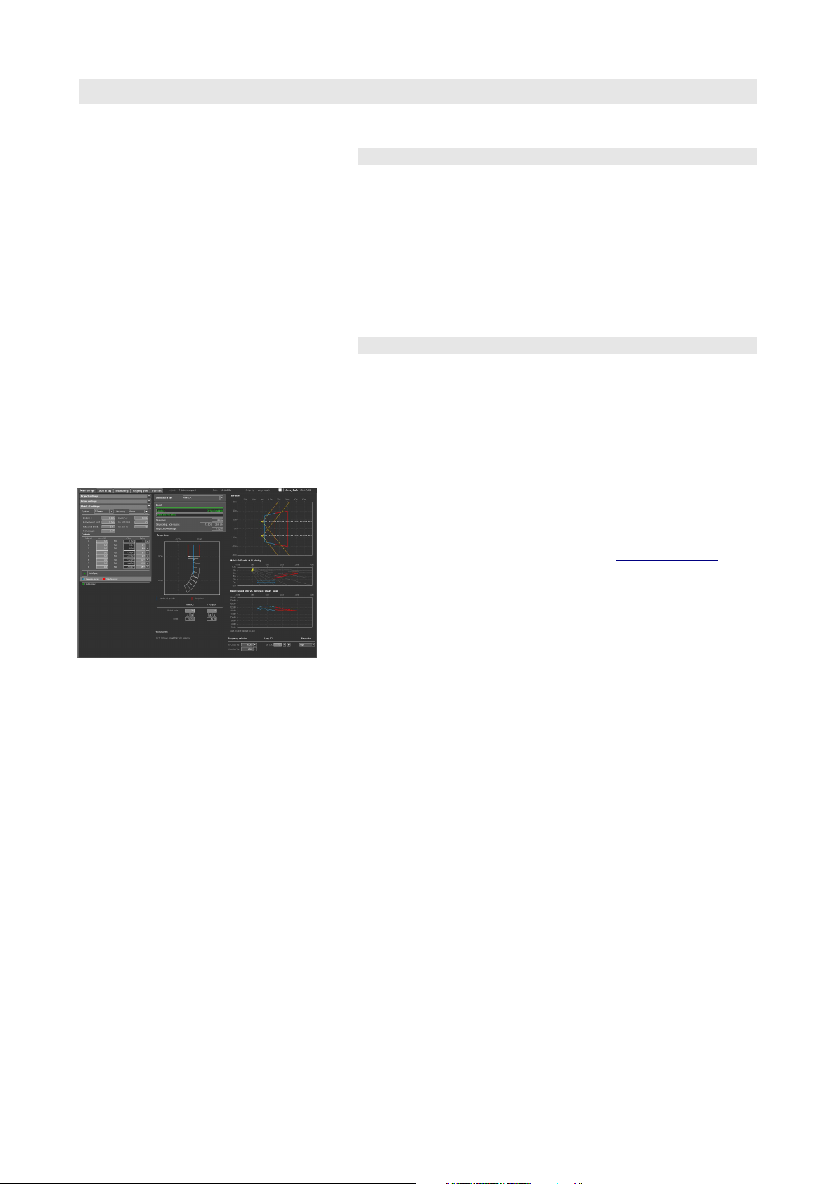
1.2.1. ArrayCalc / TI 385
For arrays with a total system weight of more than 665 kg (1466 lb) the
load conditions within the array have to be checked using the ArrayCalc
array calculator, which can be downloaded at
The use of ArrayCalc is described in "TI 385 J-, Q and T-Series system
design, d&b ArrayCalc" which is also supplied with the Z5300 J Flying
frame.
This TI includes typical array configurations within the permitted load
limits.
Carefully read this TI to become familiar with the operation and
behaviour of ArrayCalc and in particular with the mechanical load
conditions and limitations.
We also recommend to attend the regularly hosted d&b J-Series
training seminars. Further information of the d&b seminars can be
requested directly from d&b audiotechnik sales partners.
www.dbaudio.com.
J-Series Rigging manual (1.3 EN) Safety precautions - 1/Page 4 of 34
Page 5

1.3. Operational safety
During assembly pay attention to the possible risk of crushing hazard.
Wear suitable protective clothing.
Observe the weight of the J-Series loudspeaker cabinets and the J
Flying frame. Single person lift could cause injury – Lifting Hazard!
Always use assistance when moving or lifting.
Observe all instructions given on the rigging components (Flying frame,
Load adapter) and the loudspeaker cabinets.
When chain hoists are in operation ensure that there is nobody directly
underneath or in the proximity of the load.
Under no circumstances climb on the array.
J-Series Rigging manual (1.3 EN) Page 5 of 34
Page 6
2. J-Series rigging concept
2.1. Z5300 J Flying frame
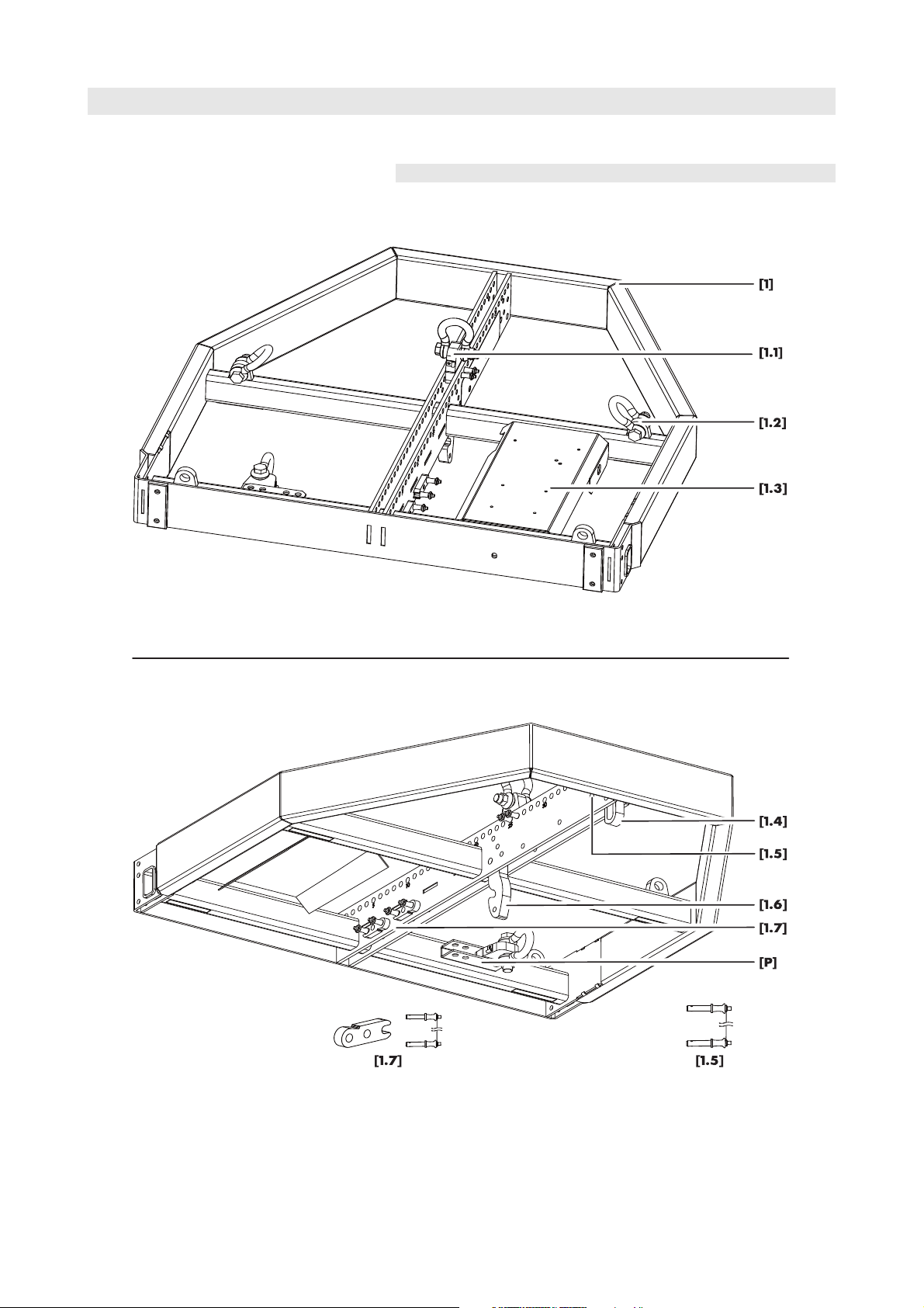
The Z5300 J-Flying frame is equipped and supplied with the following
rigging components:
Fig. 1: Z5300 J Flying frame top and bottom view
J-Series Rigging manual (1.3 EN) Page 6 of 34
Page 7

2.1.1. System components overview
Pos. Component Description
Z5300 J Flying frame The Z5300 J Flying frame is designed to support arrays consisting of
[1]
the following J-Series loudspeakers:
Code Type Weight incl. rigging comp.
Z0650 J8 60 kg (132 lb)
Z0651 J12 60 kg (132 lb)
Z0660 J-SUB 106 kg (234 lb)
The weight of the J Flying frame including all rigging components is
65 kg (143 lb)
[1.1]
[P]
J Load adapter
Park position J Load adapter
The J Flying frame is supplied with two J Load adapters to allow single
or dual hoist set up. Each J Load adapter is supplied with a pair of
Locking pins 12 mm and a 3.25 t shackle. During transport the Load
adapters should be stored at their park position [P]. (please refer to
section 3.5 Suspension of the Z5300 J Flying frame on page 13)
[1.2]
Safety point(s) The J Flying frame is equipped with a total of four safety points to
attach a secondary safety using the Z5303 J Safety chain and 3.25 t
Shackles. (please refer to section 3.6 Secondary safety on page 15)
[1.3]
Mounting plate The J Flying frame is equipped with an additional mounting plate to
accept industry standard inclinometers such as Rieker Instrument
Company Inc. or SSE ProSight Inclinometer System.
[1.4]
Cable pick An O-Ring can be slid out by releasing the respective Locking pin for
attaching a cable pick.
[1.5]
Locking Pins 11 mm Two additional Locking pins 11 mm are supplied with the Flying frame
and are located beside the cable pick. They are used to connect JSeries cabinets on top of the Flying Frame for the following set ups:
[1.6]
[1.7]
• Mixed J-Series array with J-SUB cabinets at the top of the column.
(Section. 4.2 Variant 2: J-SUB and J8/J12 Arrays from page 22)
• J-Series ground stack with the J Flying frame as ground support.
(Section. 4.4 Variant 4: J-Series ground stacks from page 26)
Splay link (Frame) In conjunction with the Front links of the J-Series loudspeaker cabinets
the Splay link of the frame is used to attach the first cabinet to the
frame. By factory default the Splay link of the frame is fixed in J8/J12
position. To accept J-SUB cabinets the Splay link can be moved to JSUB position. (please refer to section ofon page )
During transport the Splay link should be fold back to its park position
and secured by the respective Locking pin.
Front link (Frame) Two additional Front links together with a pair of Locking pins 10 mm
each are supplied with the J Flying frame. They are used to connect JSeries cabinets on top of the Flying Frame for the following set ups:
• Mixed J-Series array with J-SUB cabinets at the top of the column.
(Section. 4.2 Variant 2: J-SUB and J8/J12 Arrays from page 22)
• J-Series ground stack with the J Flying frame as ground support.
(Section. 4.4 Variant 4: J-Series ground stacks from page 26)
J-Series Rigging manual (1.3 EN) Page 7 of 34
Page 8
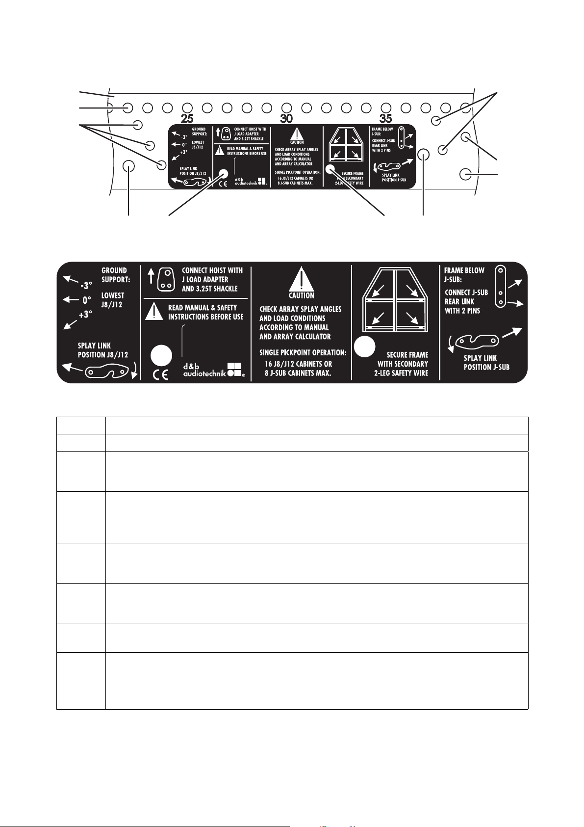
2.1.2. Z5300 J Flying frame center bar
[2.1]
[2.2]
[2.3a] [2.3b]
[2.4b]
[2.4a]
[2.5b]
[2.5a]
[2.6][2]
Fig. 2: Z5300 J Flying frame center bar with user instructions
Fig. 3: Z5300 J Flying frame user instructions
Position Description
[2]
[2.1]
Center bar of the Flying frame with user instructions.
Main hole grid at the top of the center bar with a total of 39 holes numbered with an increment of five.
Using the J Load adapters the Flying frame can be suspended from one or two pick points. (please refer to
the sections 3.5.2 Single hoist set up on page 14 and 3.5.3 Dual hoist set up on page 14)
[2.2]
Hole grid ground stack: when J8/J12 cabinets are attached to the top of the frame this hole grid indicates
the possible settings of –3°, 0° or +3° for the Splay link of the lowest cabinet. The Splay link is to be
connected to the frame using the additional Locking pins [1.5]. (refer to section 4.4 Variant 4: J-Series
ground stacks from page 26)
[2.3a]
[2.3b]
Fixing point for the frame's Splay link in J8/J12 position. (refer to section 3.4 Splay link position at the
Z5300 J Flying frame on page 12). The additional hole [2.3b] is used to fix the Splay link in its park position
using the respective Locking pin.
[2.4a]
[2.4b]
Fixing point for the frame's Splay link in J-SUB position. (refer to section 3.4 Splay link position at the Z5300
J Flying frameon page 12). The additional hole [2.4b] is used to fix the Splay link in its park position using the
respective Locking pin.
[2.5a]
[2.5b]
[2.6]
Fixing point for the Cable pick (O-Ring). The additional hole [2.5b] is used to fix the O-Ring in its park
position using the respective Locking pin.
Fitting the Flying frame below a J-SUB cabinet (Mixed J-Series array with J-SUB cabinets at the top of the
column) these two holes are used to fix the Rear link of the respective J-SUB cabinet to the frame using the
two additional Locking pins [1.5]. (refer to section 4.2 Variant 2: J-SUB and J8/J12 Arrays from page 22)
These holes can also be used to park the two additional Locking pins [1.5] during transport.
J-Series Rigging manual (1.3 EN) Page 8 of 34
Page 9
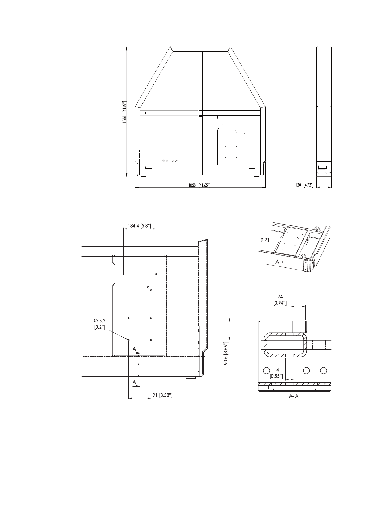
2.1.3. Z5300 J Flying frame dimensions
Fig. 4: Z5300 J Flying frame dimensions in mm [inch]
2.1.4. Dimensions of the Mounting plate [1.3]
Fig. 5: Mounting plate dimensions in mm [inch]
J-Series Rigging manual (1.3 EN) Page 9 of 34
Page 10
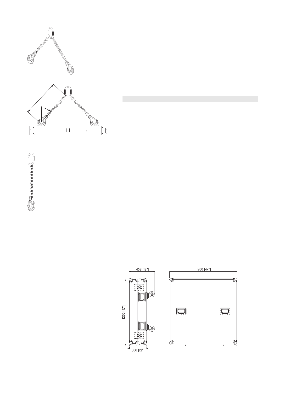
Fig. 6: Z5303, J Safety chain
β
630 mm
Fig. 7: Z5303, J Safety chain -
Nominal length and sling β
β.
ββ
2.1.5. Z5303 J Safety chain
The Z5303 J Safety chain is supplied with the J Flying frame and is used
as a secondary safety. (Please refer to section 3.6. Secondary safety on
page 15)
Z5303 Specifications
Lifting chain..........................................................................2-leg, 10 mm (DIN EN 818)
Nominal length incl. hooks for sling angle β = 45°.......................................630 mm
Maximum sling angle [β
Load rating..............................................................................................5.6 t (β: 0° - 45°)
....................................................................................................................4 t (β: 46° - 60°)
].........................................................................................60°
Max
2.2. Optional components
2.2.1. Z5305 J Hoist connector chain
The Z5305 J Hoist connector chain is used to connect the lifting motor(s)
to the J Flying frame using the 3.25 t Shackles which is attached to the
J Load adapter. Its length of 53 cm (21") allows enough space for the
hang of most 2 t motor chain containers and avoids any influence to the
vertical balance of the array when suspended from a single pick point.
Z5305 Specifications
Lifting chain..........................................................................1-leg, 10 mm (DIN EN 818)
Nominal length incl. hook......................................................................................535 mm
Load rating..........................................................................................................................4 t
Fig. 8: Z5305 J Hoist connector chain
2.2.2. E7441 Touring case 1 x Z5300 J Flying frame
The E7441 Touring case is designed to store one J Flying frame
together with the Z5303 J Safety chain set and two Z5305 J Hoist
connector chains. Its empty weight is 66 kg (146 lb). The overall weight
is 145 kg (320 lb - including the Flying frame and all chain sets).
Using the E7441 Touring case the Flying frame can be assembled or
picked up in different ways as described in:
4.1 Variant 1: J8/J12 Array
Fitting the J Flying frame
on page 18.
4.2 Variant 2: J-SUB and J8/J12 Arrays
Preparation and assembly of the second Flying frame
on page 24.
Fig. 9: E7441 Touring case for 1 x Z5300 J Flying frame,
dimension in mm [inch]
J-Series Rigging manual (1.3 EN) Page 10 of 34
Page 11
WARNING!
LOCK PIN
SECURELY
BEFORE LIFTING
CAUTION
ONLY UNLOCK FOR
DISASSEMBLY ON
GROUND
3. Preparation
3.1. General preparations
Check the acoustical and mechanical set up with the ArrayCalc array
calculator and prepare enough print outs for each array.
Using the plan, the riggers are able to set up the suspension points, the
securing points and the chain hoists.
The working load limit of the chain hoists and their
suspension points has to be high enough to carry the
total system weight.
As during a dual hoist set up the motors might not
always be synchronized each of the suspension points
has to be able to carry the total system weight.
When on site first clear the working areas, check that the hoists are
exactly in the specified position, the chains are not twisted and there is
enough space to set up and lift the array.
3.2. Inspections
All system components must be inspected for faults before use. This also
includes the loudspeaker and in particular the rigging parts of the
cabinets.
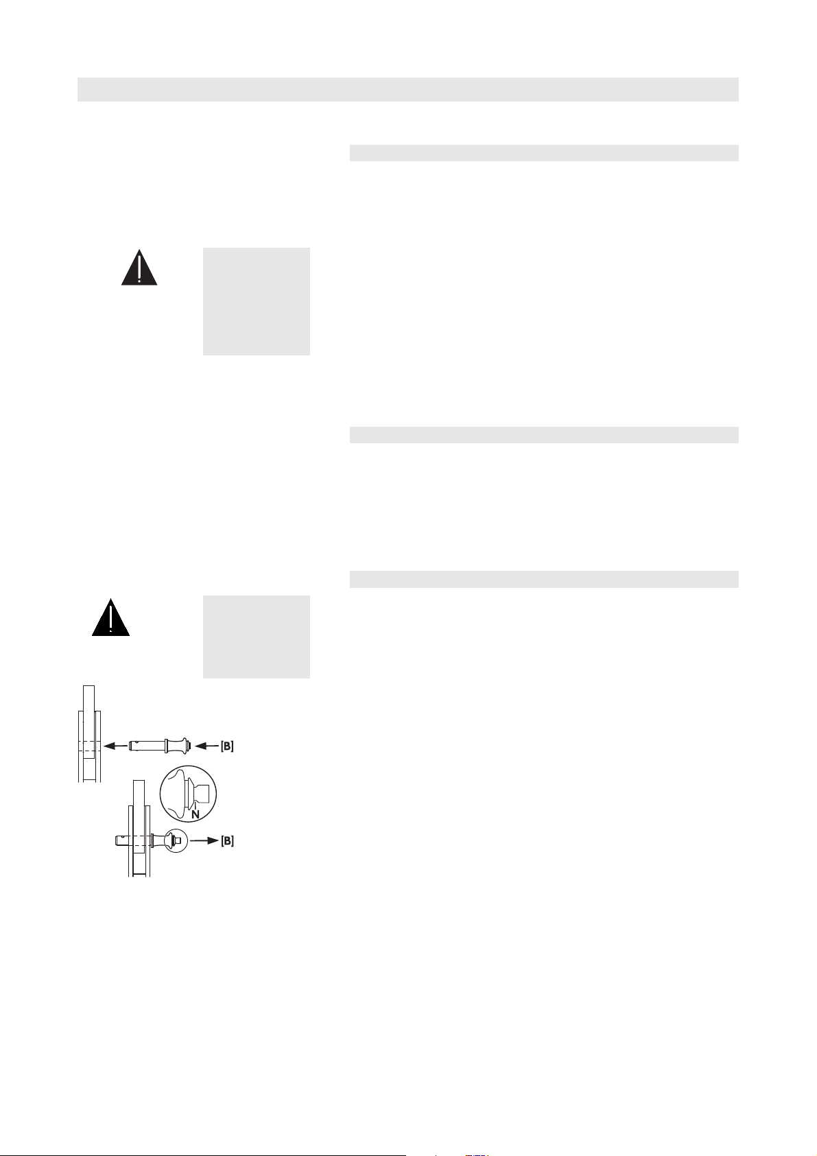
WARNING!
Fig. 10: J-Series Locking pins, Quicklock
Damaged components must be withdrawn from use immediately. Please
pay attention to section 6. Care and maintenance / Disposal on page
31 of this manual.
3.3. J-Series Locking pins
The steel wire between the locking pins is not meant to
suspend a cabinet or carry any load. The cabinet's weight
must only be carried by the Front and Splay links in
conjunction with front and rear rigging strands of the
loudspeaker cabinets
Assembly
1. Pressing the button [B] releases the locking mechanism allowing
insertion through the respective links or sockets.
2. Releasing the button after the pin is inserted and fixed in place the
locking mechanism will be locked. A groove [G] (Fig. 10) in the bolt
of the pin indicates that it is properly locked.
J-Series Rigging manual (1.3 EN) Page 11 of 34
Page 12

Within the J-Series Rigging system the following types of Locking pins
are used:
J-Series Loudspeaker (J8/12 and J-SUB)
• Locking pins 10 mm for the cabinet Front links. Linked in pairs with a
steel wire and undetachably fixed to the cabinet.
• Locking pins 11 mm for the Splay (Rear) link at the central rear
rigging strand. Linked in pairs with a steel wire and undetachably
fixed to the cabinet.
• Locking pin 8 mm at the wheel board undetachably fixed to the
wheel board with a steel wire.
J Load adapter/J Flying frame
• Locking pins 12 mm to attach the J Load adapter to the Flying
frame. Linked in pairs with a steel wire and undetachably fixed to
the Load adapter.
• Locking pin 11 mm for the Splay link and the cable pick of the frame
to fix the respective component in its park position. Connected to the
fixing bolt of the respective component with a rue ring cotter and a
steel wire.
• Locking pins 10 mm for the two additional Front links at the Flying
frame. Linked together in pairs with a steel wire.
WARNING!
3.4. Splay link position at the Z5300 J Flying frame
The fixing bolt of the frames Splay link is stressed by the
full load of the array.
It is essential the bolt is fitted correctly and secured by
the ring cotter when altering the position of the Splay
link.
Ensure the ring cotter is properly locked.
Depending on the type of cabinet (J8/J12 or J-SUB) to be attached to
the J Flying frame the position of the frames Splay link needs to be
altered.
Fig. 11: Splay link frame – J8/J12 position
Fig. 12: Splay link frame – J-SUB position
To change the Splay link position proceed as follows:
J-Series Rigging manual (1.3 EN) Page 12 of 34
Page 13

Release Remove/
Fit
Snap in Lock
Assembly
1. First alter the position of the additional Locking pins [1.5] as shown
in Fig. 14 - Step 1.
2. Release and remove the Locking pin of the Splay link and fold out
the Splay link.
3. Unlock and remove the ring cotter of the fixing bolt.
Fig. 13: Function of the ring cotter of the
fixing bolt (schematic diagram)
4. Remove the fixing bolt while holding the Splay link.
5. Move the Splay link to its new position and insert the fixing bolt.
6. Secure the fixing bolt with the ring cotter and ensure the ring cotter
is properly locked.
Step 1 Step 2 Step 3
Step 4/5 Step 6
Fig. 14: Altering the Splay link position of the frame
3.5. Suspension of the Z5300 J Flying frame
3.5.1. J Load adapter
WARNING!
The suspension of the J Flying frame is carried out using one or two J
Load adapter fitted with a 3.25 t shackle, depending on the chosen type
of suspension (Single or Dual hoist set up).
The Load adapter(s) are attached to the center bar of the Flying frame
and fixed with the two Locking pins 12 mm of the Load adapter.
Ensure the Load adapter is properly attached to the
center bar of the frame and both Locking pins are
inserted and locked securely before lifting the array.
Fig. 15: J Load adapter
Before attaching the Load adapter check the 3.25 t.
shackle is properly fitted to the Load adapter and
secured against loosening.
J-Series Rigging manual (1.3 EN) Page 13 of 34
Page 14

Fig. 16: ArrayCalc
Hole position for Single hoist set up
Fig. 17: Direction of the J Load adapter
for full grid (1/1 Pickpoint Detent)
Shown: Hole 16
Fig. 18: Direction of the J Load adapter
for half grid (1/2 Pickpoint Detent)
Shown: Hole 16,5
3.5.2. Single hoist set up
When suspending the array from a single pick point (Single Pick point
Operation) the following limits apply:
Maximum system weight of 1025 kg (2260 lb) or
accordingly:
• Max. 16 x J-TOP cabinets (J8/J12)
• Max. 8 x J-SUB cabinets
In "Single Pickpoint Operation" the position of the J Load adapter
defines the vertical aiming of the whole array.
The corresponding hole position is calculated using ArrayCalc (Fig. 16)
and can be set in a 1/2-hole resolution at the top of the center bar of
the J Flying frame.
The J Load adapter allows a full grid (1/1 Pickpoint Detent) or a half
grid (1/2 Pickpoint Detent) setting depending on its direction of
attachment (Fig. 17/18).
The frame's hole index marked on one side of the center bar of the
frame is the reference for the direction of the Load adapter.
Attaching the Load adapter
1. Choose the appropriate hole position in the J Flying frame center
bar according to the ArrayCalc simulation and attach the J Load
adapter correspondingly.
If ArrayCalc displays a half numbered hole setting (half grid) turn
the J Load adapter correspondingly (refer to Fig. 18)
Fig. 19: Single hoist set up
Fig. 20: ArrayCalc
Hole positions for Dual hoist set up
2. Connect the Z5305 J Hoist connector chain to the 3.25 t Shackle of
the J Load adapter.
3.5.3. Dual hoist set up
When suspending the array from two pick points the following limits
apply:
Maximum system weight of 1.5 t (3300 lb) or accordingly:
• Max. 24 x J-TOP cabinets (J8/J12)
• Max. 14 x J-SUB cabinets
With Dual hoist setup the vertical aiming of the array will be set by
trimming the hoist motors after the array is fully assembled and lifted to
its operating position. The corresponding hole positions of the Load
adapters is calculated using ArrayCalc - Fig. 20.
Attaching the Load adapter
1. Choose the appropriate hole positions for the Front and Rearpick in
the J Flying frame center bar according to the ArrayCalc simulation
and attach the J Load adapters correspondingly (Direction: Full grid
1/1 Pickpoint Detent).
2. Connect one Z5305 J Hoist connector chain each to the 3.25 t
shackle of the respective J Load adapter.
Fig. 21: Dual hoist set up
J-Series Rigging manual (1.3 EN) Page 14 of 34
Page 15

3.6. Secondary safety
WARNING!
The secondary safety suspension must be independent of
the primary suspension points and capable of carrying
the total system weight.
The additional safety device must be mounted in a way
that the array is caught by the safety device without any
drop and swing in the event that the primary suspension
fails.
3.6.1. Secondary safety at the Z5300 J Flying frame
The Z5300 J Flying frame is equipped with four safety points [1.2]. Two
are located at the front bar and two at the cross bar of the frame. The
latter being the default suspension for the secondary safety are fitted
with two 3.25 t shackles.
We recommend the use of the Z5303 J Safety chain set which is
supplied with the J Flying frame.
Assembly
1. Before attaching the safety device ensure the two 3.25 t shackles
are properly fitted to the frame and secured against loosening with
a locked ring cotter - Fig. 22.
2. When attaching the Safety chain set ensure the chains are not
twisted and the hooks [H] are in the right direction as shown in in the
graphic below - Fig. 23.
Fig. 22: Ring cotter to secure
the 3.25 t shackle [S].
Fig. 23: Secondary safety at the Flying frame
J-Series Rigging manual (1.3 EN) Page 15 of 34
Page 16

3.7. Horizontal aiming and securing of the array
against rotation
WARNING!
Fig. 24: Safety points of the frame for
horizontal aiming and protection against
rotation and swing
If the system is used in an open air environment the
influence of wind has to be taken into account. The
protection against rotation and swing has to withstand
higher forces. Refer to section 5. Wind loads on page 30.
After the array has been lifted to its operating position the horizontal
aiming has to be set and the array should be secured against rotation
and swing.
The protection should be applied to the remaining safety points of the
Flying frame - Fig. 24.
J-Series Rigging manual (1.3 EN) Page 16 of 34
Page 17

4. J-Series arrays and assembly
J-Series loudspeakers and J Flying frames may be assembled in the
following ways.
Variant 1: J8/J12 Array
(Refer to section 4.1 starting from page 18)
Variant 2: J-SUB and J8/J12 Array
(Refer to section 4.2 starting from page 22)
Alternative variant 3: J-SUB Array
(Refer to section 4.3 starting from page 26)
Variant 4: J Ground stacks
(Refer to section 4.4 starting from page 26)
J-Series Rigging manual (1.3 EN) Page 17 of 34
Page 18

4.1. Variant 1: J8/J12 Array
4.1.1. Preparations and order of assembly
The array can be assembled on the ground completely without the need
of lifting the cabinets by hand. On their wheel boards the cabinets can
be easily moved into position and joined together.
1. Prepare the flying cables and link cables according to the number of
amplifier channels and cabinets used.
a)
b)
c)
Fig. 25: Front links assembly
2. Arrange the cabinets in the right order and direction to be joined
together as follows:
Joining the cabinets together (Fig. 25a – c)
3. With one person on each side of the cabinets first release and
remove both Locking pins of the cabinet's Front links. The links can
be accessed through the holes in the wheel boards and slid out to
their stop position. (Fig. 25a)
4. Insert one pin to the respective socket to fix the Front links in place.
(Fig. 25b)
5. Insert the Front links into the front rigging strands of the next cabinet
and lock them with the second pin (Fig. 25b).
Repeat steps 3 to 5 in the same manner until all cabinets are joined
together.
Note: For an easy attachment of the Flying frame it is advisable to
connect at least two cabinets before fitting the Flying frame to the top
cabinet as described below.
Fitting the J Flying frame (Fig. 26, Fig. 27a/b; Fig. 28)
The J Flying frame can be fitted to the top cabinets Front links using the
E7441 Touring case. The Touring case enables the J Flying frame to be
positioned in the exact vertical level of the cabinet Front links. To do so
the Flying frame must be positioned with the hole grid of the center bar
facing down and the front of the frame facing towards the wooden
baseboard of the Touring case.
Fig. 26: J Flying frame within the E7441
Touring case
a) b)
Fig. 27: J Flying frame assembly
6. Prepare the Front links of the top cabinet in the same manner as
done in step 3 and 4.
7. With one person on each side open the case and tilt the J Flying
frame upright using the wooden baseboard of the Touring case and
position it towards the top cabinet of the column.
8. Release the velcro strips of the Touring case which hold the Flying
frame in place.
9. Move the cabinets towards the frame until the Front links of the first
cabinet are completely inserted into the front tracks of the Flying
frame. (Fig. 27a)
10. Insert and lock the Locking pins of the cabinet to the respective holes
of the Flying frame. (Fig. 27b)
J-Series Rigging manual (1.3 EN) Page 18 of 34
Page 19

Fig. 28: Splay link of the frame connected
to the first cabinet
Fig. 29: Preset the splay angles
11. Release and remove both Locking pins of the central rigging strand
at the rear of the top cabinet.
12. Release and remove the Locking pin of the frame's Splay link and
fold it out.
13. Attach the Splay link to the central rigging strand at the rear of the
top cabinet and lock it with the two pins of the cabinet (0° and 4°
hole - Fig. 28) and remove the Touring case.
Rig the cabling
14. Connect the flying cables and link cables according to the number of
amplifier channels and cabinets used.
Preset the splay angles (0° ... 6° settings; Fig. 29)
Note: The maximum splay angle of 7° is not being preset. For the 7°
position both Locking pins will be fixed later during the lifting procedure
described from step 21 when the full splay is reached.
15. Preset the splay angle of each cabinet according to your ArrayCalc
simulation by inserting one pin to the respective hole of the central
rigging strand.
16. Release the other pin which is holding the Splay link in place and put
it aside. This pin is used to secure the Splay link when fixing the splay
angles in a later step.
17. Swing off the Splay link of the cabinet to the central rigging strand
of the next cabinet.
Attach the pick point
Fig. 30: J Load adapter fitted and hoist
connected
18. Depending on the type of suspension (single or dual hoist set up as
described in section 3.5 on page 13) attach the J Load adapter to
the center bar of the J Flying frame and connect the hoist. (Fig. 30)
Attach the secondary safety device
19. At this point of the set up we recommend to attach the secondary
safety device using the Z5303 J Safety chain set as described in
section 3.6 Secondary safety on page 15.
Checking the actual set up
20. Before continuing with the set up it is recommended to check the
actual status of the assembly as follows:
• Check the assembly of the Flying frame to the first cabinet
(Front and Splay links) and ensure all Locking pins are
properly locked.
• Check the attachment of the Load adapter(s) to the Flying
frame and ensure all Locking pins are properly locked.
• Check the assembly of the secondary safety device at the
Flying frame. (refer to section 3.6 on page 15)
• Check the assembly of all Front links to both sides of the
cabinets and ensure all Locking pins are properly locked.
• Check the preset splay angles.
J-Series Rigging manual (1.3 EN) Page 19 of 34
Page 20

Fix the splay angles
21. Lift the Flying frame using the hoist until the first Splay link has
hooked over the preset Locking pin. (Fig. 31a/b)
22. Lower the Flying frame until the second securing Locking pin can be
inserted into the hole below the preset pin. (Fig. 31b)
23. Repeat this procedure of lifting and lowering cabinet by cabinet until
all splay angles are fixed and the Splay links are secured with the
Locking pins.
Alternatively this procedure can be applied to a group of cabinets in
a)
one step. In this case lift the Flying frame using the hoist until all Splay
links of the group have hooked over their preset Locking pins (0° ... 6°).
Lower the Flying frame and insert the remaining securing Locking pins
until all splay angles are fixed and all Splay links are secured.
Remove the wheel boards (Fig. 32a-c)
The wheel boards have a fixed pin at one side and a removable pin to
the other side and they can be fitted to the cabinet either way around.
Using the recessed holes on top the wheel boards can easily be stacked
and stored aside.
24. Rise the array until the wheel board of the top cabinet is in an
accessible height.
b)
Fig. 31: Fixing the splay angles
a) b)
c)
Fig. 32: Removing the wheel boards
25. With one person on each side of the cabinets first release the pin
while holding the wheel board.
26. Slightly fold off the board and move it towards the other side to
release the fixed pin.
27. Take off the wheel board.
28. Remove all accessible boards in the same manner.
29. Lift the array to get access to the remaining wheel boards and
remove them in the same manner.
Check the whole set up
30. Check the assembly of the Splay/Rear links at the rear of the
cabinets and ensure all Splay links are secured with two pins..
31. Check the wiring.
If the amplifiers are already wired and powered on, using their
System check function or channel mute switches and a test signal the
correct function and routing of all channels and cabinets can be
verified.
Hoisting and securing the array
When all the mechanical adjustments, system checks and safety checks
have been made the array can be hoisted up to its operating position.
When hoisting the array, ensure that the loudspeaker cables do not get
caught anywhere. The cables can be strapped together with the motor
cable to form a loom while the system is hoisted.
The chain hoist motors must raise the system slowly and evenly so that it
does not swing or move from side to side during hoisting.
When the array is in its final operating position the secondary safety
must be applied. A detailed description is given in 3.6 Secondary safety
on page 15.
J-Series Rigging manual (1.3 EN) Page 20 of 34
Page 21

4.1.2. Derigging
The same safety instructions as for the set up apply and the following
order is recommended:
1. Lower the array and stop before the lowest cabinet hits the ground.
2. Attach the wheel boards beginning with the lowest cabinet.
3. Continue to lower the array and carefully tip the lowest wheel
board onto the ground.
4. Stop lowering the array at this point.
RIGHT!
WARNING!
WRONG!
Continuing lowering the array at this point could lead to
the potential risk to tip over the array towards the front
before - depending on the type of ground (arena
floor/free field) - the array could roll towards the back in
a sudden.
This will cause a potentially dangerous situation which
may lead to personal injury.
In particular make sure that during lowering the array
no person is underneath or within the vicinity of the
array.
Before continuing lowering the array with one person to
each side of the array give support to the side handles of
the lowest cabinet. While lowering the array give
direction towards the back of the array to ensure the
array will be lowered straight down and safely rolled to
the back. It is advisable all persons involved in lowering
the array are close by to give instructions if necessary.
5. Continue to lower the array and with one person on each side of
the cabinets attach the remaining wheel boards.
6. When all wheel boards are attached the array can be fully dropped
onto the ground.
7. Remove the cabling.
8. Remove the lower Locking pins which were used to secure the Splay
links.
9. Lift the Flying frame until the full curving of the array is reached and
the hooks of the Splay links are released.
10. Flip back the Splay links to their park position and fix them with the
Locking pin.
11. Lower the Flying frame again until all cabinets stand on their wheel
boards.
12. Remove the Flying frame and store all items (Splay link / Load
adapter) back into their park positions.
13. Separate the cabinets and store back the Front links into their park
position.
J-Series Rigging manual (1.3 EN) Page 21 of 34
Page 22

4.2. Variant 2: J-SUB and J8/J12 Arrays
Unlike an array of J-TOP cabinets only with mixed configurations the
cabinets are lifted and attached to the array one by one.
For flown arrays of J-SUB and J8/J12 cabinets two J Flying frames must
be used.
CAUTION!
If the array contains J-SUB cabinets these must always
be positioned at the top of the column.
4.2.1. Preparations and order of assembly
1. Prepare the flying cables and link cables according to the number of
amplifier channels and cabinets used.
2. Decide where to fix the cable pick depending on single or dual hoist
suspension.
Preparation and suspension of the first frame
3. The Splay link of the first frame must be fitted in J-SUB position.
Check the position of the Splay link and alter the position if
necessary as described in section 3.4 Splay link position at the
Z5300 J Flying frameon page 12.
4. Depending on the chosen type of suspension (single or dual hoist set
up as described in section 3.5 Suspension of the Z5300 J Flying
frame on page 13) attach the J Load adapter to the center bar of
the J Flying frame.
5. Connect the hoist(s) to the Load adapter(s).
Attaching the secondary safety device
6. At this point of the set up we recommend to attach the secondary
safety device using the Z5303 J Safety chain set as described in
section 3.6 Secondary safety on page 15.
J-Series Rigging manual (1.3 EN) Page 22 of 34
Page 23

Preparation and assembly of the first J-SUB cabinet
(Fig. 33a-k)
7. Remove the transport lid of the J-SUB
8. Release and remove both Locking pins of the cabinet's Front links
and slid out to their stop position (Fig. 33a).
a) b)
c) d)
e) f)
9. Insert one pin to the respective socket to fix the Front links in place
as shown in Fig. 33b.
10. Lift the Flying frame using the hoist to allow the J-SUB to be
positioned below the frame.
11. Fold out the Splay link of the frame (J-SUB position) by releasing the
respective Locking pin (Fig. 33c).
12. With one person to each side of the J-SUB tip the cabinet on its
bottom panel and position the cabinet below the frame (Fig. 33d).
13. Release and remove both Locking pins at the top of the central
rigging strand at the rear of the cabinet (Fig. 33e).
14. Lower and position the frame on the top panel of the cabinet (Fig.
33f).
15. Insert and lock the Locking pins of the cabinet to the respective holes
of the Flying frame (Fig. 33g).
16. IMPORTANT: Alter the position of the Locking pin at the cabinet
as shown in (Fig. 33h/i).
17. Fix the Splay link of the frame at the central rigging strand at the
rear of the cabinet using both Locking pins (Fig. 33j).
18. Lift the assembly to a suitable height and fold out the Rear link at the
bottom of the central rigging strand at the rear of the J-SUB cabinet.
g) h)
i) j)
k) l)
Fig. 33: Preparation and assembly J-SUB
The assembly is now prepared for the attachment of further J-SUB
cabinets or the second Flying frame.
Attaching further J-SUB cabinets
The assembly of further J-SUB cabinets is carried out in the same
manner as described above.
19. Lift the assembly to a suitable height to allow the next J-SUB to
positioned below.
20. Prepare the next J-SUB and place the cabinet below the assembly.
21. Lower and position the assembly on the prepared J-SUB cabinet
and lock all Locking pins.
22. Repeat this procedure for all further J-SUB cabinets including
cabling.
J-Series Rigging manual (1.3 EN) Page 23 of 34
Page 24

Preparation and assembly of the second Flying frame
(Fig. 34a – j)
To allow J8/J12 cabinets to be attached below J-SUB cabinets a second
J Flying frame must be used as an adapter.
The J Flying Frame can be picked up by the flown J-SUB column directly
from the E7441 Touring case. For this purpose the Flying frame needs
to be positioned in the case with the hole grid of the center bar facing
upwards and the front of the frame facing towards the wooden
baseboard of the case.
Note: The graphics opposite are without the Touring case.
Prepare the second Flying frame as follows:
23. The Splay link of the frame must be fitted in J8/J12 position. Alter
the position if necessary as described in section 3.4 Splay link
position at the Z5300 J Flying frame on page 12.
a) b)
c) d)
e) f)
24. Remove the additional Front links [1.7] together with the Locking pins
from the park position at the frame.
25. Attach the Front links at the top of the front tracks of the frame and
fix them with the Locking pins. Observe the direction of attachment Fig. 34a/b.
26. Release and slide out the cable pick [1.4] by removing the respective
Locking pin and refit the Locking pin back to its socket - Fig. 34c.
27. Remove the additional Locking pins [1.5] from the park position at
the frame - Fig. 34d. These Locking pins are used to fix the Rear link
of the lowest J-SUB cabinet to the frame in a later step.
28. Lower and position the prepared J-SUB assembly on the Flying
frame in the Touring case - Fig. 34e/f.
29. Connect the Front links to the lowest J-SUB cabinets using the
Locking pins - Fig. 34g/h.
30. Fix the Rear link of the respective J-SUB cabinet to the frame using
the additional Locking pins [1.5] - Fig. 34i/j.
g) h)
i) j)
Fig. 34: Preparation and assembly second
Flying frame
J-Series Rigging manual (1.3 EN) Page 24 of 34
Page 25

a) b)
Attach the J8/J12 cabinets (Fig. 35a-j)
31. Lift the array to a suitable height using the hoists.
32. Fold out the Splay link of the frame (J8/J12 position) - Fig. 35a.
33. Preset the Locking pin at the central rigging strand at the rear of the
first cabinet to the 0° position - Fig. 35b.
34. Fold out the Splay link of the first cabinet - Fig. 35c.
35. Prepare the Front links of the cabinet - Fig. 35d.
36. With one person at each side of the cabinet remove the wheel
board and lift the cabinet with the front grill facing towards the
front. Insert the Front links into the rigging tracks at the front of the
frame.
c) d)
e) f)
g) h)
37. Fix the cabinets Front links at the frame with the Locking pins - Fig.
35e.
38. Lift the back of the cabinet until the Splay link of the frame has
hooked over the Locking pin at the rear rigging strand of the
cabinet.
39. Secure the Splay link with the second Locking pin using the 4°
position. - Fig. 35f.
40. Attach all further cabinets in the same manner. Proceed as follows:
• Preset the desired Splay angle at the respective cabinet (0°
... 6°) at the central rigging strand at the rear of the cabinet
by inserting the respective Locking pin. 7° degrees settings
are done when the cabinet is being attached to the array –
see Fig. 35g – cabinet can swing out to the front.
• Prepare the Front links as shown in Fig. 35d.
• Fold out the Splay link. (not necessary for lowest cabinet of
the array)
• Lift the cabinet and insert the Front links into the cabinet
above and fix the Locking pins.
• Lift the back of the cabinet until the its Splay has hooked
over the Locking pin of the cabinet above.
• Secure the Splay link with the second Locking pin using the
hole below the preset pin.
i) j)
Fig. 35: Preparation and attachment of the J8/
J12 cabinets
Rig the cabling
41. Connect the flying cables and link cables according to the number of
amplifier channels and cabinets used. If the amplifiers are already
wired and powered on, using their System check function or channel
mute switches and a test signal the correct function and routing of all
channels and cabinets can be verified.
J-Series Rigging manual (1.3 EN) Page 25 of 34
Page 26

a) b)
Fig. 36: J-SUB Front Link
Setting of the Locking pins for 0° or 2°
Hoisting and securing of the array
When all the mechanical adjustments, system checks and safety checks
have been made the array can be hoisted up to its operating position.
When hoisting the array, ensure that the loudspeaker cables do not get
caught anywhere. The cables can be strapped together with the motor
cable to form a loom while the system is hoisted.
The chain hoist motors must raise the system slowly and evenly so that it
does not swing or move from side to side during hoisting.
When the array is in its final operating position the secondary safety
must be applied. A detailed description is given in 3.6 Secondary safety
on page 15.
4.2.2. Derigging
To lower the array and dismantle it, follow the assembly instructions in
reverse order. The same safety instructions apply.
4.3. Variant 3: J-SUB Array
The set up of SUB arrays is carried out in the same manner as
described in section 4.2 Variant 2: J-SUB and J8/J12 Arrays from page
22 (Steps 1 – 21 - Fig. 33a-k.
If desired J-SUB arrays can also be curved. Depending on the chosen
socket for the Locking pins of the J-SUB Front links a splay angle of 0°
(Fig. 36a) or 2° (Fig. 36b) can be applied to the front of the cabinet. The
splay angle of 2° is achieved by the slot in the J-SUB Front links and will
only be effective when the array gets lifted.
WARNING!
4.4. Variant 4: J-Series ground stacks
Ground stacked set ups must always be secured against
movement and possible tipping over.
4.4.1. Limitations for J-Series Ground stacks
The following limitations apply:
• A maximum of six J-TOP (J8/J12) cabinets mounted on the J Flying
frame.
• A maximum of four J-SUB cabinets and six J-TOP (J8/J12) cabinets
mounted on the J Flying frame on top of the J-SUB cabinets.
4.4.2. Preparations
For both applications the Splay link of the frame must be fitted in J-SUB
position. Check the position of the Splay link and alter the position if
necessary as described in section 3.4 Splay link position at the Z5300 J
Flying frame on page 12.
J-Series Rigging manual (1.3 EN) Page 26 of 34
Page 27

Fig. 37: Hole grid [2.2]
4.4.3. J8/J12 ground stack assembly
The hole grid [2.2] (Ground stack) at the Flying frame (Fig. 37) allows
the first J-TOP cabinet to be set to an fixed vertical aiming of –3°, 0° or
+3°.
1. Place the Flying frame on the ground with the hole grid of the center
bar facing upwards.
2. Remove the additional Front links [1.7] and the respective Locking
pins from the park position at the frame.
3. Attach the Front links at the top of the front tracks of the frame and
fix them with the Locking pins. Observe the direction of attachment Fig. 38a/b.
4. Remove the additional Locking pins [1.5] from the park position at
the frame. These Locking pins will be used in a later step to fix the
Splay link of the lowest J-TOP cabinet to the frame.
a) b)
Fig. 38: J8/J12 Ground stack
Preparation of the Flying frame
a) b)
5. With one person at each side of it attach the first cabinet to the
Flying frame inserting the additional Front links of the frame into the
rigging tracks at the front of the cabinet and connecting them using
the second Locking pins - Fig. 39a/b.
6. Remove the wheel board.
7. Fold out and insert the Splay link of the cabinet into the track of the
center bar of the frame and fix it to the frame using one of the
additional Locking pins. In this case the hole (drill) of the cabinet's
Splay link is used. It supports the cabinet and defines the angle
setting in the hole grid of the frame (–3°, 0° or +3°) - Fig. 39c.
8. The second pin is not needed and should be stored in a hole of the
center grid of the frame.
9. Prepare the Front links of the cabinet to allow the next cabinet to be
attached.
10. Preset the splay angle (0° ... 6°) to the cabinet above at the rear
rigging strand by inserting one Locking pin to the respective hole.
c) Hole grid Ground stack
Fig. 39: J8/J12 Ground stack
Assembly of the first cabinet at the Flying
frame
J-Series Rigging manual (1.3 EN) Page 27 of 34
Page 28

11. Remove the wheel board of the next cabinet.
12. Add the next cabinet. With one person to each side of the cabinet
insert the Front links to the rigging tracks at the front of the cabinet Fig. 40a.
13. Fix the cabinets Front links with the second Locking pins - Fig. 40b.
14. Fold out the Splay link of the cabinet and connect it to the cabinet
below as follows:
a)
b)
c)
Fig. 40: Attaching the J8/J12 cabinets
• Lower the back of the cabinet until the Splay link has
hooked over the preset Locking pin.
• Raise the back of the cabinet until the Splay link has
completely hooked into the Locking pin.
• Insert the second Locking pin to fix the desired splay angle.
15. Attach all cabinets in the same manner until the assembly is
completed.
Wiring
16. Connect the cables and link cables according to the number of
amplifier channels and cabinets used.
Securing the set up
Secure the ground stack against movement and possible tipping over.
Derigging
To dismantle the ground stack, follow the assembly instructions in
reverse order. The same safety instructions apply.
J-Series Rigging manual (1.3 EN) Page 28 of 34
Page 29

4.5. Ground stack with J-SUB and J8/J12
Setting up a ground stack consisting of J-SUB and J8/J12 cabinets first
the subwoofer cabinets are stacked on the floor and connected
together with their Front and Rear links - Fig. 41. The J Flying frame is
placed on top of them to support the J8/J12 cabinets
a) b)
Fig. 41: Interconnection of the J-SUBs
a)
Set up
1. Remove the transport lid of the J-SUB cabinet.
2. With one person at each side of the J-SUB tip the cabinet on its
bottom panel.
3. For additional J-SUB cabinets proceed in the manner as described in
step 1 and 2 and position the cabinets on top of each other.
4. Interconnect the cabinets with the Front and Rear links of the
cabinets - Fig. 41.
Attaching the Flying frame
5. Position the Flying frame on top of the uppermost J-SUB cabinet with
the hole grid of the center bar facing upwards.
6. Fix the Flying frame to the top J-SUB cabinet with the Front links of
the cabinet and the Splay link of the frame (J-SUB position).
Attaching the J8/J12 cabinets
7. The assembly of the J8/J12 cabinets on top of the J-SUB cabinets is
carried out in the same manner as described in section 4.4.3 J8/J12
ground stack assembly on page 27.
Wiring
8. Connect the cables and link cables according to the number of
amplifier channels and cabinets used.
b)
Fig. 42:J-SUB and J8/J12 Ground stack
Assembly of the Flying frame
a) b)
Fig. 43: Interconnection of the J-SUBs
Securing the set up
9. Secure the ground stack against movement and possible tipping
over.
Derigging
To dismantle the ground stack, follow the assembly instructions in
reverse order. The same safety instructions apply.
4.5.1. J-SUB stacks
Conventional J-SUB stacks are set up in the same manner as described
in the previous section. For conventional ground stacks of J-SUB
cabinets we also recommend to interconnect the cabinets with their
Front and Rear links - Fig. 43.
Secure the stack against movement and possible tipping over.
J-Series Rigging manual (1.3 EN) Page 29 of 34
Page 30

5. Wind loads
When loudspeaker arrays are flown in an open air environment,
possible wind effects should be taken into account. Wind load will
produce additional dynamic forces to the rigging components and the
suspension, which may lead to a dangerous situation.
WARNING!
bft knots km/h mph Description Effects on land
0 0-1 0-1 0-1 Calm
1 1-3 1-5 1-3 Light Air
2 4-6 6-11 4-7 Light breeze
3 7-10 12-19 8-12 Gentle breeze
4 11-16 20-28 13-18 Moderate breeze
5 17-21 29-38 19-24 Fresh breeze
6 22-27 39-49 25-31 Strong breeze
7 28-33 50-61 32-38 Near gale
8 34-40 62-74 39-46 Gale
9 41-47 75-88 47-54 Severe gale
10 48-55 89-102
11 56-63 102-117 64-72 Violent storm
12 > 64 > 117,0 > 72 Hurricane
55-63
Generally flying loudspeakers overhead at wind forces
higher than 6 bft is not recommended.
When planning an open air event it is essential to get current weather
and wind information.
The following wind speed scale according to Beaufort gives an
impression of the effects of the different wind forces (bft).
Smoke rises vertically.
Direction of wind shown by smoke drift, but not by wind vanes.
Wind felt on face; leaves rustle; ordinary vanes moved by wind.
Leaves and small twigs in constant motion; wind extends light
flag.
Raises dust and loose paper; small branches are moved.
Small trees in leaf begin to sway; crested wavelets form on
inland waters.
Large branches in motion; whistling heard in telegraph wires;
umbrellas used with difficulty.
Whole trees in motion; inconvenience felt when walking against
the wind.
Breaks twigs off trees; generally impedes progress.
Slight structural damage occurs (chimney-pots and slates
removed).
Storm
Trees uprooted; considerable structural damage occurs.
Accompanied by wide-spread damage.
Heaviest damage and destruction.
Tab. 1: Wind force and its effects on land
WARNING!
WARNING!
If according to the forecast wind forces higher than 5 bft
are possible the following actions have to be taken:
•••• The actual on site wind speed has to be monitored
permanently. Be aware that wind speed typically
increases with height above ground.
•••• Suspension and securing points of the array should be
designed to accommodate double the static load in
order to withstand any additional dynamic forces.
If the wind force exceeds 8 bft there is a risk of
mechanical damage to the components which may lead
to a dangerous situation for persons in the vicinity of the
flown array.
Stop the event and make sure that no one is left within
the vicinity of the array.
Lower down and secure the array.
J-Series Rigging manual (1.3 EN) Page 30 of 34
Page 31

6. Care and maintenance / Disposal
6.1. Transport / Storing
During transport ensure the rigging components are not stressed or
damaged by mechanical forces. Use suitable transport cases.
Due to their surface treatment the J-Series rigging components are
temporarily protected against moisture. However, ensure the
components are in a dry state while stored or during transport and use.
6.2. Visual and functional inspection
Cabinet enclosure:
• Visual inspection of all fitting plates for obvious damage (e.g. cracks
or corrosion).
• Inspection of all fitting plates including front grills to ensure they are
securely attached.
• Regularly lubricate the sockets with WD-40
Locking pins
• Visual inspection regarding deformation and corrosion of the
component.
®
or a similar product.
• Inspection for missing ball bearings and damage.
• Functional inspection of the release mechanism to check it functions
properly.
• Regularly lubricate Locking pins with WD-40
®
or a similar product.
Front and Splay (Rear) links
Visual inspection regarding deformation and damage (e.g. cracks and
corrosion) including all drilled holes of the component.
Z5300 J Flying frame
• Visual inspection regarding deformation and damage (e.g. cracks
and corrosion) including all drilled holes of the component.
• Regularly check the flatness of the Flying frame. For this purpose
position the Flying frame on a flat surface and visually check the
frame for deformation and/or torsion. For obvious deformation
and/or torsion contact d&b audiotechnik for further advice and how
to proceed.
Z5303 J Safety chain
Z5305 J Hoist connector chain
Inspection according to the appropriate regulations for lifting devices
(EN 818-6:2000 Regularly inspection within a 12 month period.
Regularly inspection for cracks within a 36 month period).
6.3. Disposal
When out of use the rigging components must be disposed in
accordance to the national environmental regulations.
Ensure that damaged rigging components are disposed in a way that
they can not be used again.
J-Series Rigging manual (1.3 EN) Page 31 of 34
Page 32

EC Declaration of Conformity
within the meaning of the EC Machine Directive 98/37/EEC
We hereby declare that the equipment designated below is designed and built in the version sold by us in such a way as
to comply with the relevant fundamental safety and health criteria of the applicable EC Directive(s). This declaration shall
cease to be valid if alterations are made to the equipment without our prior agreement.
This declarations covers:
•••• d&b Z5300, J Flying frame including:
•••• d&b J Load adapter
•••• d&b J Front link Frame
•••• d&b J Splay link Frame
•••• d&b J Locking pins
•••• d&b Z5303 J Safety chain set
•••• d&b Z5305 J Hoist connector chain
•••• d&b J-Series loudspeaker cabinets (with integrated rigging components):
•••• d&b Z0650, J8 loudspeaker
•••• d&b Z0651, J12 loudspeaker
•••• d&b Z0660, J-SUB loudspeaker
Relevant EC Directives:
EC Machine Directive 98/37/EC
National standards and technical specifications applied, in particular:
DIN EN ISO 12 100, DIN EN 1050, BGV C1
Backnang 2007-02-16
(Frank Bothe, Director)
d&b audiotechnik GmbH, Eugen-Adolff-Str. 134, D-71522 Backnang, Germany, Phone +49-7191-9669-0, Fax +49-7191-95 00 00_______
Page 33

Page 34

D2983.EN .01, 05/2012 © d&b audiotechnik GmbH
d&b audiotechnik GmbH, Eugen-Adolff-Str. 134, D-71522 Backnang, Germany, Phone +49-7191-9669-0, Fax +49-7191-95 00 00_______
 Loading...