

Page 1
D80
D
Manual 1.9 en
Page 2

General information
D80 Manual
Version: 1.9 en, 06/2015, D2020.EN .01
Copyright © 2015 by d&b audiotechnik GmbH; all rights
reserved.
Keep this manual with the product or in a safe place
so that it is available for future reference.
We recommend you to regularly check the d&b website for the
latest version of this manual.
When reselling this product, hand over this manual to the new
customer.
If you supply d&b products, please draw the attention of your
customers to this manual. Enclose the relevant manuals with the
systems. If you require additional manuals for this purpose, you
can order them from d&b.
d&b audiotechnik GmbH
Eugen-Adolff-Strasse 134, D-71522 Backnang, Germany
T +49-7191-9669-0, F +49-7191-95 00 00
docadmin@dbaudio.com, www.dbaudio.com
Page 3

IMPORTANT SAFETY INSTRUCTIONS
Explanation of graphical symbols
The lightning symbol within a triangle is intended to alert
the user to the presence of uninsulated "dangerous
voltages" within the unit’s chassis that may be of
sufficient magnitude to constitute a risk of electric shock
to humans.
Before using this product, carefully read the
applicable items of the following safety instructions.
1. Keep these instructions for future reference.
2. Read these instructions.
3. Heed all warnings.
4. Follow all instructions.
5. Keep water or other liquids away from the unit. Do not place
liquid filled containers, for example beverages, on top of the
unit.
6. Do not operate the unit while it is wet or standing in liquid.
7. Always operate the unit with the chassis ground wire
connected to the electrical safety earth. Do not defeat the
safety purpose of a grounding-type plug. A grounding-type
plug has two blades and a third grounding prong. The third
prong is provided for your safety. If the provided plug does
not fit into your outlet, consult an electrician for replacement of
the obsolete outlet.
8. Do not use this unit if the power cord is damaged or frayed.
Protect the power cord from being walked upon or pinched,
particularly at the plugs and the point where it exits from the
apparatus.
9. The unit is intended for use in a 19" rack. Follow the mounting
instructions. When a rack on wheels is used, exercise caution
when moving the loaded rack to avoid injury from tipping
over.
10. Unplug this apparatus during lightning storms or when unused
for long periods of time.
The exclamation point within a triangle is intended to
alert the user to the presence of important operating and
service instructions in the literature accompanying the
product.
11. Never connect an output pin to any other amplifier input or
output pin or to the earth (ground). This may damage the unit
or lead to electric shock.
12. Lay all cables connected to the unit carefully so that they
cannot be crushed by vehicles or other equipment and that no
one can either step on them or trip over them.
13. Refer all servicing to qualified service personnel. Servicing is
required when the apparatus has been damaged in any way
such as:
– Power-supply cord or plug is damaged.
– Liquid has been spilled into the unit.
– An object has fallen into the unit.
– The unit has been exposed to rain or moisture.
– The unit does not operate normally.
– The unit was dropped or the chassis is damaged.
– Do not remove top or bottom covers. Removal of the covers
will expose hazardous voltages. There are no user
serviceable parts inside and removal may void the warranty.
14. Use the mains plug as the disconnecting device and keep it
readily accessible. If the mains plug is not readily accessible
due to mounting in a 19" rack, then the mains plug for the
entire rack must be readily accessible.
15. An experienced user must always supervise the equipment,
especially if inexperienced adults or minors are using the
equipment.
d&b D80 Manual 1.9 en 3
Page 4

Contents
1. Introduction........................................................................ 6
1.1. Intended use............................................................................ 6
1.2. D80 Concept........................................................................... 6
2. Technical specifications.................................................. 8
3. Scope of supply.............................................................. 10
4. Startup............................................................................... 11
4.1.
Overview............................................................................... 11
4.2. Rack mounting and cooling................................................. 12
4.3. Connections.......................................................................... 14
4.3.1. Mains connection.............................................................. 14
4.3.2. Audio INPUT and LINK connectors................................. 16
4.3.3. Output connectors............................................................. 17
4.3.4. ETHERNET (Dual Ethernet port)........................................ 18
4.3.5. CAN (CAN-Bus)................................................................ 19
4.4. Controls and indicators........................................................ 20
4.4.1. Mains power switch.......................................................... 20
4.4.2. Display - User interface..................................................... 20
4.4.3. Standby mode................................................................... 21
4.4.4. Mute functions................................................................... 22
5. User interface.................................................................. 23
5.1.
Operating concept............................................................... 23
5.2. Screen layout and conventions............................................ 24
5.3. Screen items and views........................................................ 24
5.3.1. Function buttons................................................................. 24
5.3.2. Navigation buttons............................................................ 24
5.3.3. Input fields.......................................................................... 25
5.3.4. Input masks........................................................................ 25
5.3.5. Information fields............................................................... 25
6. Home screen.................................................................... 26
Header area - Device........................................................... 27
6.1.
6.2. Data area - Channel strip(s)................................................. 27
7. Channel strip.................................................................... 28
8. Basic settings - Quick reference............................... 30
9. Device setup..................................................................... 32
Device name......................................................................... 33
9.1.
9.2. Input....................................................................................... 34
9.2.1. Input mode......................................................................... 34
9.3. Output................................................................................... 36
9.3.1. Output mode..................................................................... 37
9.4. Remote................................................................................... 41
9.4.1. IP settings........................................................................... 41
9.4.2. Remote ID.......................................................................... 42
9.5. More...................................................................................... 42
9.5.1. Preferences........................................................................ 42
9.5.1.1. Display............................................................................ 43
9.5.1.2. Lock................................................................................. 43
9.5.1.3. Preferences/More.......................................................... 45
9.5.1.3.1. System reset................................................................ 46
9.5.2. Info..................................................................................... 46
9.5.3. Levels.................................................................................. 47
9.5.4. Mains current limiter (MCL).............................................. 48
9.5.5. AmpPresets........................................................................ 49
d&b D80 Manual 1.9 en4
Page 5

9.5.6. Scope................................................................................. 50
10. Channel setup.................................................................. 51
10.1. Channel name.................................................................... 52
10.2. Configuration switches - Filter_1, _2, _3.......................... 53
10.3. Level.................................................................................... 53
10.4. EQ - Equalizer ................................................................... 53
10.5. DLY - Delay......................................................................... 56
10.6. Input routing........................................................................ 56
10.7. System check/LM............................................................... 57
10.7.1. System check................................................................... 57
10.7.2. Load monitoring (LM)..................................................... 58
10.8. Speaker............................................................................... 59
10.8.1. ArrayProcessing (AP)...................................................... 61
10.8.2. LoadMatch...................................................................... 62
10.8.3. LINEAR setup................................................................... 63
10.9. Frequency generator - Freq. gen....................................... 63
11. Web Remote interface................................................. 65
12. Operation (Hardware references)......................... 68
12.1.
Power supply...................................................................... 68
12.1.1. Active Power Factor Correction (PFC)........................... 68
12.1.2. Automatic mains range selection................................... 68
12.1.3. Mains voltage monitoring.............................................. 68
12.1.4. Mains inrush current limiter............................................ 69
12.1.5. Mains supply requirements............................................ 69
12.1.6. Generator operation/UPS requirements....................... 70
12.2. Power amplifiers................................................................. 70
12.3. Cooling fans....................................................................... 71
12.4. Current/power draw and thermal dissipation.................. 71
13. Service/Maintenance and care................................ 73
Service................................................................................. 73
13.1.
13.2. Maintenance and care...................................................... 73
13.2.1. Touch screen cleaning.................................................... 73
13.2.2. Touch screen calibration................................................. 74
14. Manufacturer's Declarations.................................... 75
EU declaration of conformity (CE symbol)....................... 75
14.1.
14.2. WEEE Declaration (Disposal)............................................ 75
14.3. Licenses and Copyright...................................................... 75
15. Appendix.......................................................................... 76
System check - References................................................. 76
15.1.
15.2. Max. number of cabinets operated in parallel................ 78
15.3. Error messages................................................................... 80
d&b D80 Manual 1.9 en 5
Page 6
1. Introduction
1.1. Intended use
The d&b D80 amplifier is designed for mobile applications and
intended to be used with all current d&b loudspeakers. A LINEAR
setup is available allowing the D80 to be used as a linear power
amplifier.
NOTICE!
The device complies with the electromagnetic compatibility
requirements of EN 55103 (product family standard for audio,
video, audio-visual and entertainment lighting control apparatus for
professional use) for the environments E1 (residential), E2 (business
and commercial), E3 (outdoor use in urban areas) and E4
(outdoor use in rural areas).
Acoustic interference and malfunctions may occur if the unit is
operated in the immediate vicinity of high-frequency transmitters
(e.g. wireless microphones, mobile phones, etc.). Damage to the
device is unlikely, but cannot be excluded.
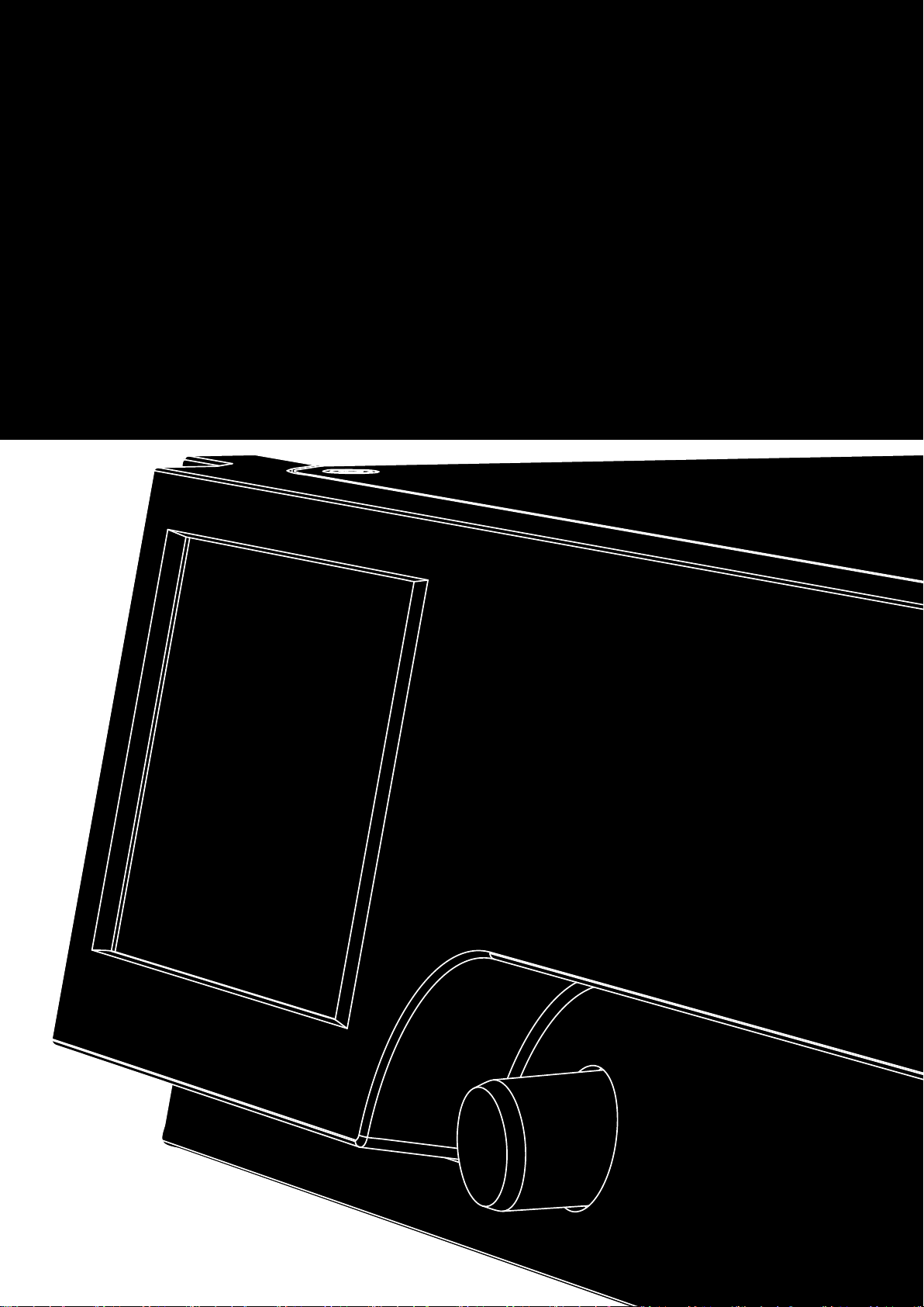
D80 Front view
1.2. D80 Concept
The D80 amplifier represents the next generation of high power
four channel Class D amplifiers. It is developed and manufactured
by d&b using Digital Signal Processing (DSP) to incorporate
loudspeaker specific configurations and user definable setups,
equalization and delay functions. The amplifier is designed to fully
drive all d&b loudspeakers and provide comprehensive
management and protection capabilities. This high performance
amplifier provides the power density required for both touring and
installation purposes while the powerful signal processing extends
the level of functionality of the on-board features.
The user interface of the amplifier consists of two elements: a color
TFT touch screen providing visual information and quick access to
the amplifier settings and a rotary encoder on the front panel for
data input purposes. To allow ease of operation when the amplifier
is below eye level, the front panel and the integrated display are
tilted upwards. As a result, the front panels of multiple amplifiers on
top of each other within a rack integrate to form one large control
surface.
The user definable equalizer features two independent 16-band
EQ groups within each channel. These provide parametric, notch,
shelving and asymmetric filters as well as a graphic EQ (via the
d&b R1 Remote control software V2) allowing instant switching
between two EQ curves for comparison. The delay capability
covers a range of up to 10 s. All loudspeaker specific functions
such as CUT, HFA, HFC, CSA or CPL are available. The DSP unit of
the amplifier has a fixed latency of 0.3 ms.
D80 User interface
d&b D80 Manual 1.9 en6
Page 7

D80 Rear view
The amplifier enables up to four input channels, which may be four
analog inputs, two analog and two AES channels or four AES
channels. Each input channel can be routed to any of the output
channels A to D. XLR connectors 2 and 4 of the D80 can be used
as either digital or analog inputs, connectors 1 and 3 are analog
inputs. Link outputs are supplied for all inputs. This 1:1 ratio of
inputs to amplifier output channels increases flexibility of
application, particularly for use as monitor, frontfill or effect
channels.
The D80 amplifier outputs are optionally NL4 or EP5 connectors
plus one centered NL8 connector with all pins driven. The latter
serves as an interface to a rack panel or to loudspeaker multicores
and breakout adapters. To simplify configuration, the output mode
of the amplifier can be configured like a set of two dual channel
amplifiers providing Dual Channel, Mix TOP/SUB or 2-Way Active
modes for the left and the right channels A/B and C/D,
respectively.
For applicable loudspeakers, d&b LoadMatch enables the D80
amplifier to electrically compensate for the properties of the cable
used to connect the loudspeakers to the amplifier output. This
function which covers a bandwidth of up to 20 kHz preserves the
tonal balance when cable lengths of up to 70 m (230 ft) are used.
Due to its design LoadMatch does not require additional wires and
is therefore applicable with any connector type used.
To provide optimum compensation, cable length and crosssectional data as well as the number of loudspeakers connected to
the amplifier channel can be entered on the amplifier.
The D80 utilizes a switch mode power supply with active Power
Factor Correction (PFC) to produce a clean current draw and
ensure stable and efficient performance under adverse mains
conditions. The high power capabilities provide increased power
to fully drive all applicable d&b loudspeaker cabinets and
sufficient headroom for any future systems.
Remote control and full system integration are realized using the
d&b ArrayCalc simulation software and R1 Remote control
software V2. The D80 amplifier includes two Ethernet ports on
etherCON connectors to enable daisy chaining. Both Ethernet and
dbCAN protocols are incorporated. The Ethernet protocol
implemented in the d&b R1 Remote control software V2 and the
D80 amplifier is a protocol developed by the OCA Alliance (Open
Control Architecture Alliance), of which d&b is a founding member.
For further details, please refer to the OCA website:
www.oca-alliance.com.
d&b D80 Manual 1.9 en 7
Page 8

2. Technical specifications
Audio data (linear setting with subsonic filter)
Maximum output power per channel (THD + N < 0.5%, all channels
driven)
CF = 6 dB @ 4/8 ohms 4 x 2600/2000 W
CF = 12 dB @ 4/8 ohms 4 x 4000/2000 W
Maximum output voltage 180 V
Frequency response (—1 dB) 35 Hz – 20 kHz
THD+N 20 Hz – 20 kHz, 600 W @ 4 ohms) < 0.5%
S/N ratio (unweighted, RMS)
Analog input > 110 dBr
Digital input > 114 dBr
Damping factor (20 Hz – 200 Hz into 4 ohms) > 100
Crosstalk (20 Hz – 20 kHz) < –70 dBr
Gain (Linear mode @ 0 dB) 31 dB
Protection circuits
Mains inrush current limiter
Ground fault protection
Output current limitation/protection 65 A / 75 A
Output DC offset protection 10 V
Output HF Voltage Limiter 60 V @ 10 kHz
Output pop-noise suppression
Mains Current Limitation (MCL) 95 to 50 % of 16 / 30 A
Overvoltage protection Up to 400 V AC
Self-resetting overtemperature protection
13 A
22 A
27 A
@ 230 V AC
RMS
@ 120 V AC
RMS
@ 100 V AC
RMS
Power supply
Autosensing switched mode power supply with active power factor
correction (PFC)
Mains connector powerCON-HC
Rated mains voltage 208 to 240 V, 50 – 60 Hz
high range
100 to 127 V, 50 – 60 Hz
low range
Mains fuse internal
Audio input connectors
INPUT analog (A1 - A4) 3 pin XLR female
Pin assignment 1 = GND, 2 = pos., 3 = neg.
Input impedance 38 kOhms, electronically balanced
Common mode rejection (CMRR @ 100 Hz/10 kHz) > 70 / 50 dB
Maximum input level (balanced/unbalanced) +25 / 17 dBu
+27 dBu @ 0 dBFS
LINK analog (A1 - A4) 3 pin XLR male
Pin assignment 1 = GND, 2 = pos., 3 = neg.
INPUT digital (D1/2, D3/4) 3 pin XLR female, AES 3
Pin assignment 1 = GND, 2 = AES Signal, 3 = AES Signal
Input impedance 110 ohms, transformer balanced
Sampling 48 / 96 kHz / 2 Ch/n
Synchronization Word-Sync: PLL-locked to source (slave mode)
LINK digital (Output) 3 pin XLR male
electronically balanced
analog signal buffering (refresh), power fail relay (Bypass)
Output connectors
SPEAKER OUTPUTS A/B/C/D
4 CHANNEL OUTPUT 1 x NL8
Network connectors
CAN
ETHERNET
Dual Ethernet port with built-in 2-port Ethernet switch
Controls and indicators
POWER
SCROLL/EDIT Digital rotary encoder
Display TFT color touch screen, 3.5" / 320 x 240 Pixel
Mains power switch
parallel to input
4 x NL4
optional: 4 x EP5
2 x RJ 45 parallel
2 x etherCON
10/100 Mbit
®
Power consumption (typical values)
Standby
Idle 180 W
Max. power consumption (short term RMS) 7000 W
9 W
d&b D80 Manual 1.9 en8
Page 9
Digital Signal Processing
System start-up time 17 sec.
Sampling rate 96 kHz / 27 Bit ADC / 24 Bit DAC
Latency analog input 0.3 msec.
Latency digital input (AES) 0.3 msec.
48 kHz / 96 kHz
Input dynamic > 127 dB
ADC dynamic > 110 dB
DAC dynamic > 110 dB
Equalizer two user definable 16-band equalizers
Filter types: PEQ/Notch/HiShlv/LoShlv/Asym
Delay 0.3 msec. - 10 sec.
Frequency generator Pink noise or Sine wave 10 Hz – 20 kHz
Operating conditions
Temperature range* –10 °C ... +40 °C / +14 °F ... +104 °F
*continuous operation
Temperature range** –10 °C ... +50 °C / +14 °F ... +122 °F
**reduced output power or short term operation
Storage temperature –20 °C ... +70 °C / –4 °F ... +158 °F
Humidity (rel.), long term average 70%
Fan noise emission
Rack mounted, measured on axis, 1 m to front panel, A-weighting
Idle 34 dB(A)
Ambient temperature 22 °C / 71.6 °F
Max. RPM 49 dB(A)
Dimensions and weight
Height x width x depth
Weight 19 kg / 42 lb
2 RU x 19" x 530.5 mm
2 RU x 19" x 20.9"
D80 enclosure dimensions in mm [inch]
d&b D80 Manual 1.9 en 9
Page 10
3. Scope of supply
Before starting up the device, please verify the shipment for
completeness and proper condition of the items.
If there is any sign of obvious damage to the unit and/or the
power cord, do not operate the unit and contact your local dealer
from whom you received it.
Pos. Qty. d&b Code Description
[1] 1 Z2710 d&b D80 Amplifier, dependent on chosen output option (NL4 or EP5 output
connectors).
Including:
[2] 1 Z2620.xxx Power cord D80 (specific to country).
[3] 1 K6007.050 RJ 45 Patch cable, 0.5 m (1.6 ft) CAT 6/AWG 24-STP (shielded twisted pair) to be
used for daisy chaining multiple amplifiers within a rack.
[4] 1 Z6116 RJ 45 M Terminator for terminating the last device of a CAN-Bus segment.
[5] 1 D2020.EN .01 D80 Manual.
d&b D80 Manual 1.9 en10
Page 11
d&b audiotechnik GmbH
4. Startup
Connections
4.1. Overview
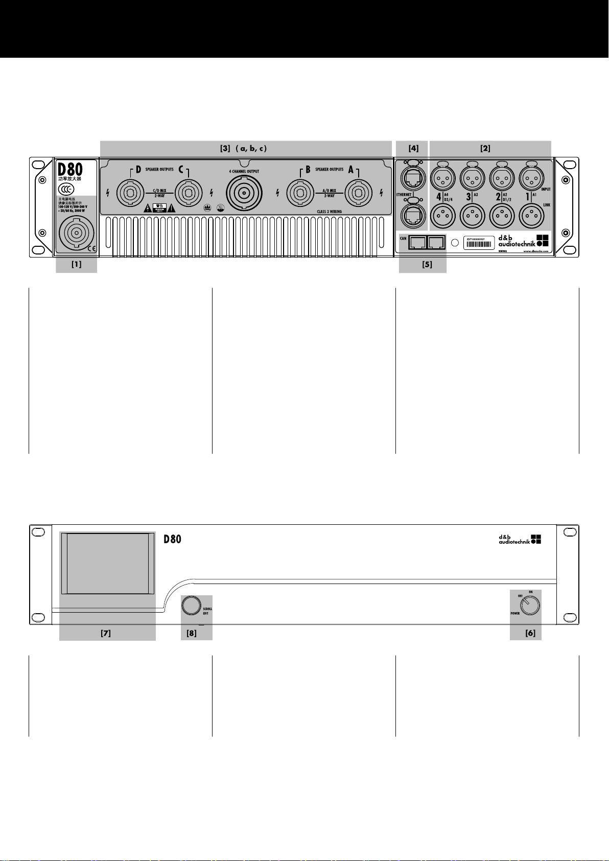
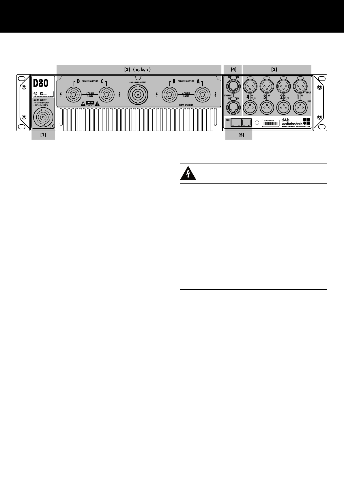
[1] Mains connector socket.
Refer to Þ Chapter 4.3.1. "Mains
connection" on page 14 and
Þ Chapter 12.1.5. "Mains supply
requirements" on page 69.
Controls and indicators - User interface
[3] Output connector panel, dependent
on chosen output option (NL4 or EP5
output connectors).
Refer to Þ Chapter 4.3.3. "Output
connectors" on page 17.
[2]
Audio INPUT (analog/digital) and
LINK connectors.
Refer to Þ Chapter 4.3.2. "Audio
INPUT and LINK connectors"
on page 16.
[4] ETHERNET.
Refer to Þ Chapter 4.3.4.
"ETHERNET (Dual Ethernet port)"
on page 18.
[5] CAN (CAN-Bus).
Refer to Þ Chapter 4.3.5. "CAN
(CAN-Bus)" on page 19.
[7] 3.5" TFT color touch screen.
[8] Rotary encoder SCROLL/EDIT.
Refer to Þ Chapter 4.4. "Controls
and indicators" on page 20 and
Þ Chapter 5. "User interface"
[6] Mains power switch.
Refer to Þ Chapter 4.4. "Controls
and indicators" on page 20,
following Þ Chapter 4.4.1. "Mains
power switch" on page 20.
on page 23.
d&b D80 Manual 1.9 en 11
Page 12
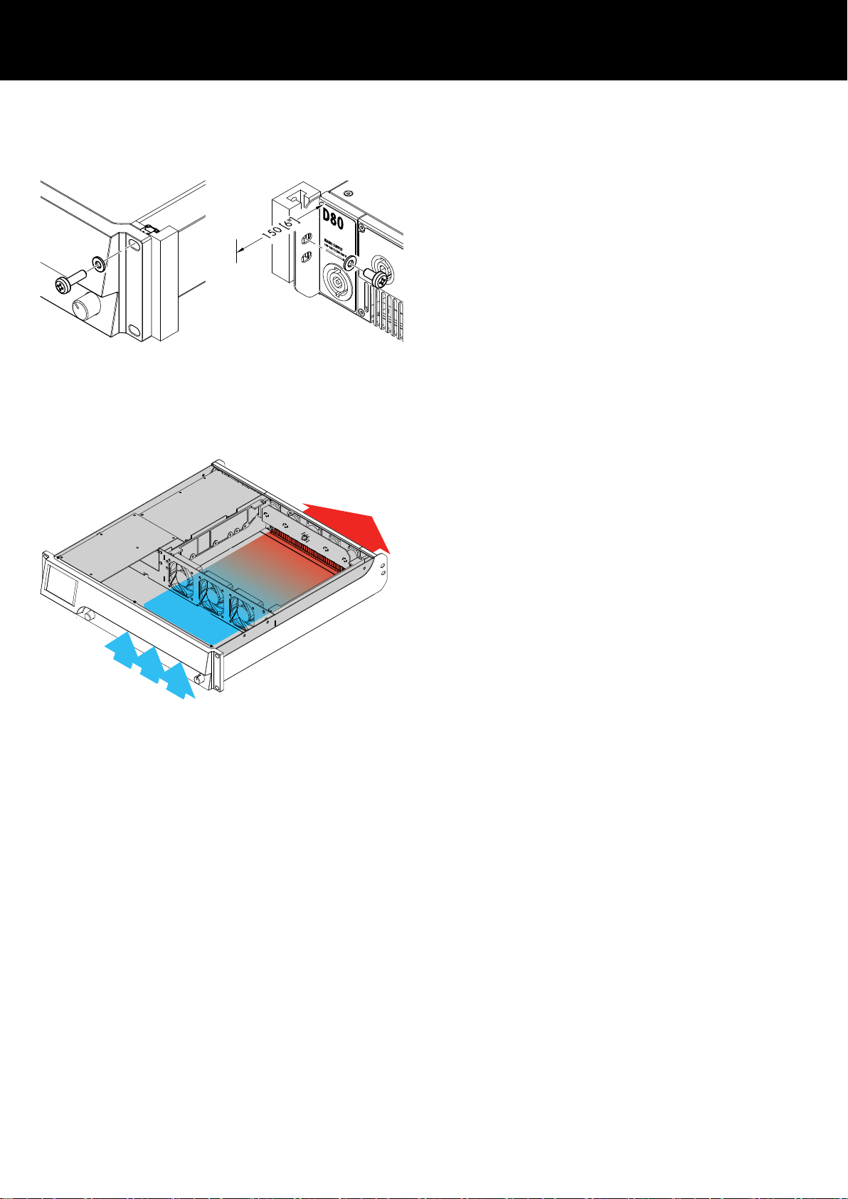
4.2. Rack mounting and cooling
Rack mounting
The D80 amplifier enclosure is designed to fit standard 19"
equipment racks or cabinets.
When specifying a rack, be sure to allow extra depth (150 mm /
6" is usually sufficient) to accommodate the cables and connectors
at the rear of the amplifier.
When mounting D80 amplifiers into a 19" rack, do not just rely on
fixing and supporting the amplifiers by their front panels using
appropriate rack mounting screws and U washers as shown in the
graphic opposite. Provide additional support ...
– by fixing the rear-mounted rack ears using appropriate rack
mounting screws and U washers as shown in the graphic
opposite. This is particularly important when amplifiers are
racked up for touring purposes.
– or using shelves fixed to the inner sides of the cabinet or rack.
Cooling
Thermal conditions are a vital factor to ensure operational safety of
the power amplifiers. The D80 amplifier is equipped with three
internal fans that draw cool air from the front into the housing and
channel the warm air towards the back of the device.
– Please ensure that adequate cool airflow is provided.
– Do not block or cover the front panel air intake or the vents on
the rear panel.
– If amplifiers are installed in sealed cabinets (e.g. in fixed
installations), use additional fan modules with filters that can
be easily replaced without opening the sealed cabinets.
– Do not combine D80 amplifiers with D6 or D12 amplifiers in
one rack.
– Do not rack up D80 amplifiers together with other devices
producing additional heat with opposing airflows.
Base heat
Unlike other amplifiers, the D80 produces a base heat of approx:
40 °C (104 °F) in the rear part of the device when idling (On,
idling). During operation, this temperature will only increase
insignificantly. Please also refer to Þ Chapter 12.4. "Current/
power draw and thermal dissipation" on page 71.
d&b D80 Manual 1.9 en12
Page 13
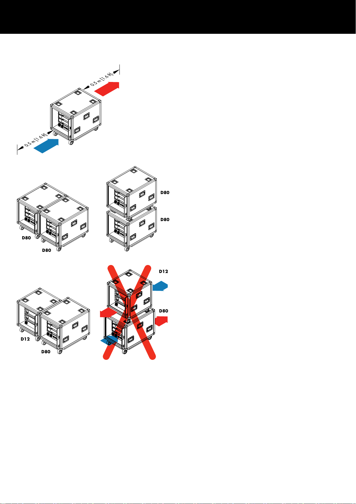
Touring rack assemblies
When using touring rack assemblies such as the d&b Z5330 D80
Touring rack assembly or any other touring rack containing D80
amplifiers, make sure to provide sufficient space of 0.5 m (1.6 ft)
at the front and rear of the touring rack to ensure adequate cooling
airflow.
D80 Touring rack assemblies can be positioned side by side or
stacked.
When combining the Z5330 D80 Touring rack assembly with the
Z5310 D12 Touring rack assembly or any other rack assembly
that produces an opposing airflow, observe the following
restrictions:
– D12/D80 Touring rack assemblies can be positioned side by
side.
– Do not stack D80 and D12 Touring racks or any other rack
assemblies with opposing airflow.
d&b D80 Manual 1.9 en 13
Page 14
4.3. Connections
4.3.1. Mains connection
WARNING!
Potential risk of electric shock.
The device is a protective class 1 unit. A missing earth (ground)
contact may cause dangerous voltages in the housing and controls
and may lead to electric shock.
– Connect the unit to mains power supplies with protective earth
only.
– If there is any sign of obvious damage to the power cord
and/or mains connector, do not use the power cord and
replace it before further use.
– Please ensure the mains connector is accessible at any time to
disconnect the unit in case of malfunction or danger.
If the mains plug is not readily accessible due to mounting in a
19" rack, then the mains plug for the entire rack must be
readily accessible.
– Do not connect or disconnect the powerCON® mains
connector under load or live.
d&b D80 Manual 1.9 en14
Page 15
NOTICE!
Due to the high power capability of the device, only operate one
device per phase conductor.
Please also refer to Þ Chapter 12.1. "Power supply"
on page 68, following Þ Chapter 12.1.5. "Mains supply
requirements" on page 69.
Mains voltage Frequency Current
100/120 V 50/60 Hz 30 A
230/240 V 50/60 Hz 15 - 16 A
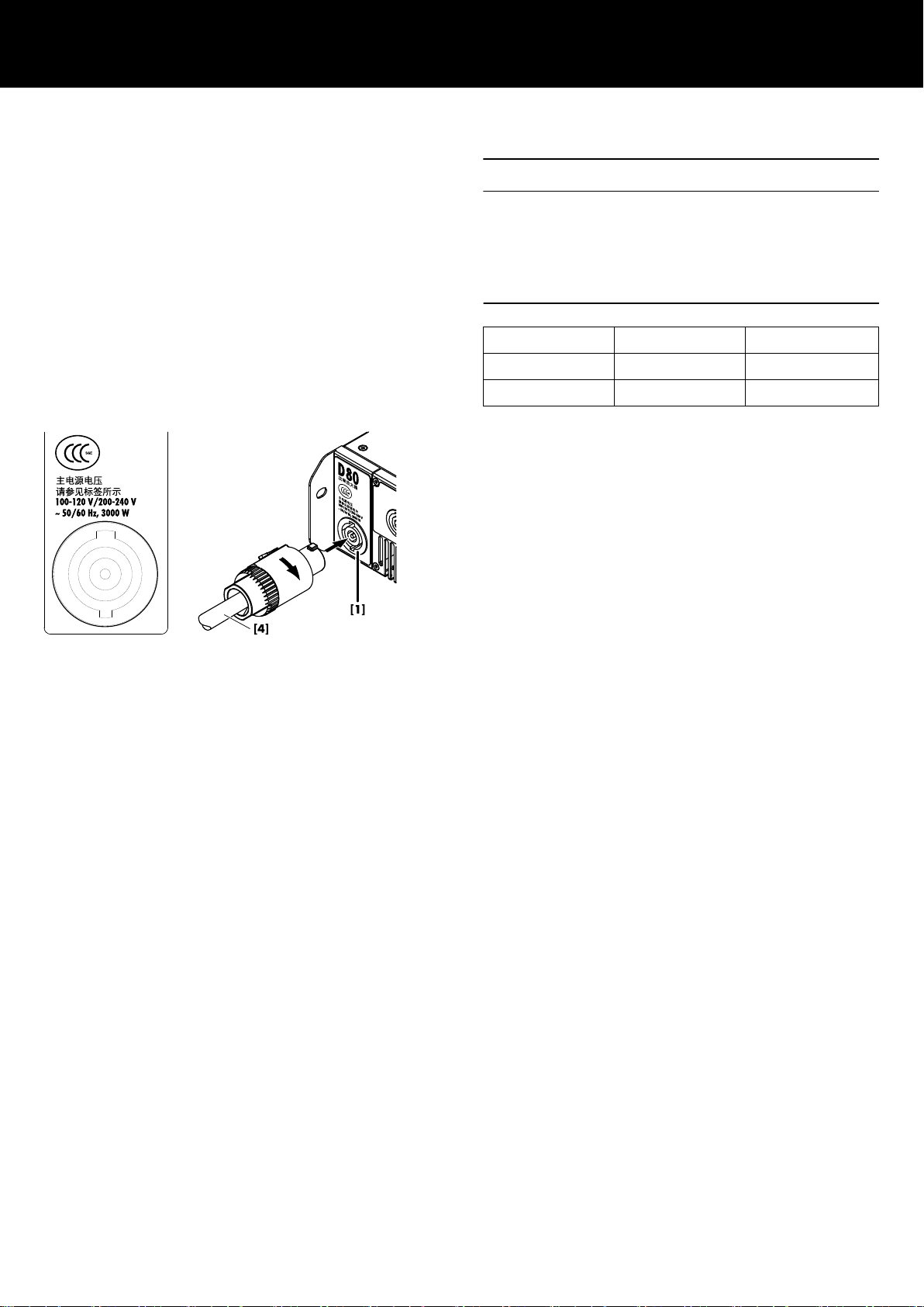
Before connecting the device to mains voltage, check that the
mains voltage and frequency correspond to the specifications on
the rating label next to the mains connector socket on the rear
panel of the unit.
A powerCON-HC® mains connector socket [1] is fitted on the rear
panel and an appropriate power cord [2] is supplied.
d&b D80 Manual 1.9 en 15
Page 16
4.3.2. Audio INPUT and LINK connectors
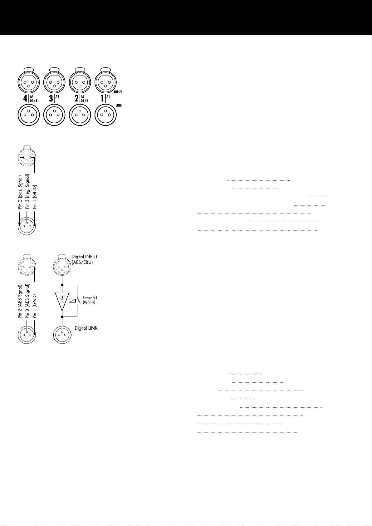
All signal input and link output connectors 1-4 are located on the
rear panel.
These can be configured as four analog inputs, two analog and
two AES channels or four AES channels (Please refer to
Þ Chapter 9.2. "Input" on page 34).
Each input channel can be routed to any of the output channels A
to D (Please refer to Þ Chapter 10.6. "Input routing"
on page 56).
Analog INPUT and LINK (A1 - A4)
A 3-pin female XLR input connector is provided for each channel.
Wired in parallel is a 3-pin male XLR input link connector used to
feed the input signal on to the next device in the signal chain.
Specifications
Pin assignment 1 = GND, 2 = pos., 3 = neg.
Input impedance 38 kOhms, electronically balanced
Common mode rejection (CMRR@100 Hz/10 kHz) > 70/50 dB
Maximum input level (balanced/unbalanced) +25/17 dBu
+27 dBu @ 0 dBFS
LINK analog (A1 - A4) 3 pin XLR male
parallel to input
Digital INPUT and LINK (D1/2 - D3/4)
The input connectors 2 (D1/2) and 4 (D3/4) can be configured
as AES/EBU (AES 3) inputs individually.
Note: When configuring the digital inputs, the remaining
input and link output connectors 1 (A1) and/or 3 (A3) are
disabled.
The corresponding digital LINK output (2/4) can be used to feed a
refreshed input signal to the next device in the signal chain. The
signal shape (the rising and falling edges of the signal) and level
are refreshed with an analog buffer amplifier.
A power fail relay is incorporated to prevent interruption of the
signal chain should there be a power failure. In this situation, the
digital input signal bypasses the analog buffer amplifier and is
routed directly to the LINK output.
Specifications
Pin assignment 1 = GND, 2 = AES Signal, 3 = AES Signal
Input impedance 110 ohms, transformer balanced
Sampling 48 / 96 kHz / 2 Ch/n
Synchronization Word-Sync: PLL-locked to source (slave mode)
LINK digital (Output) 3-pin XLR male
electronically balanced
analog signal buffering (refresh)
Power Fail Relay (Bypass)
d&b D80 Manual 1.9 en16
Page 17
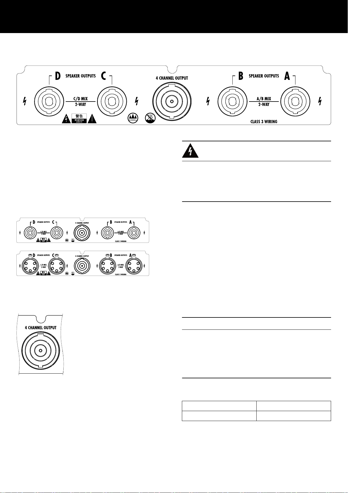
4.3.3. Output connectors
WARNING!
Potential risk of electric shock.
The amplifier output pins can carry dangerous voltages.
– Only use isolated loudspeaker cables with correctly fitted
connectors.
– Never connect an amplifier output pin to any other input or
output connector pin or protective earth (ground).
SPEAKER OUTPUTS
Depending on the chosen output option, the amplifier is supplied
with four NL4 or EP5 output connectors, one for each amplifier
output channel.
Depending on the output mode selected, the appropriate pin
assignment of the relevant output connectors is set automatically.
Note: A detailed description of the applicable output modes
and how to configure the appropriate output mode is given in
Þ Chapter 9.3.1. "Output mode" on page 37.
For further information regarding the applicable output modes
for each loudspeaker system, please refer to the relevant
loudspeaker manual.
4 CHANNEL OUTPUT
NOTICE!
The 4 CHANNEL OUTPUT connector is only intended as an
interface to a rack panel or to loudspeaker multicores and
breakout adapters.
Do not connect any loudspeaker cabinets, neither passive nor
active systems, to this connector, otherwise there is a risk of
damaging the loudspeaker components or the amplifier.
The centered NL8 connector carries the output signals of all four
amplifier channels with the following pin assignment:
1+/— = Channel A pos. / neg.
2+/— = Channel B pos. / neg.
3+/— = Channel C pos. / neg. 4+/— = Channel D pos. / neg.
d&b D80 Manual 1.9 en 17
Page 18
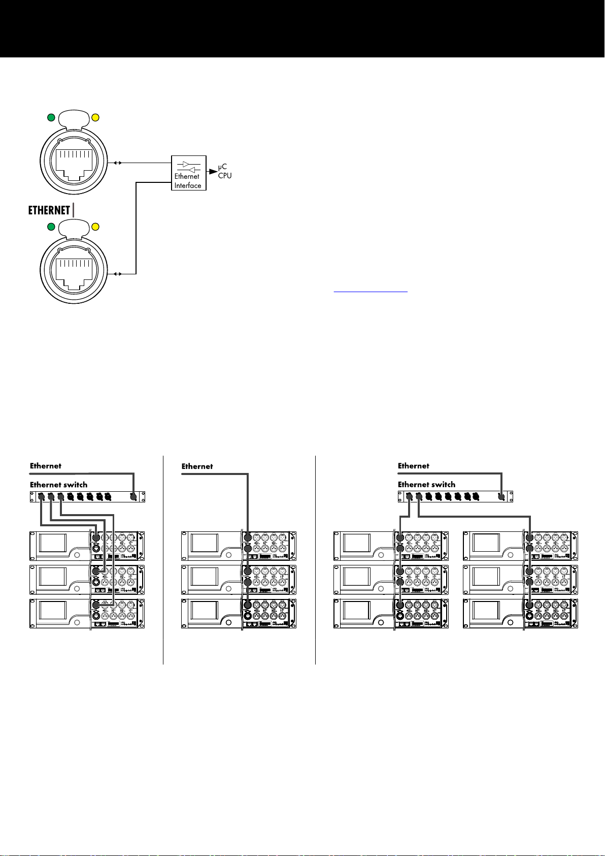
4.3.4. ETHERNET (Dual Ethernet port)
A Dual Ethernet port with a built-in 2-port Ethernet switch
(10/100 Mbit/peer-to-peer) is provided enabling remote control
via Ethernet and allows the following physical network topologies:
– Star topology
Recommended standard,
– Daisy chain topology
For a maximum of three devices,
– or a combination of both topologies.
Note: In a daisy chain topology, if one device fails or is
switched off, this also affects all subsequent devices which are
then no longer connected to the network either.
A detailed description of remote control via Ethernet is given in
the technical information TI 310 (d&b code D5310.EN) which
can be downloaded from the d&b website at
www.dbaudio.com.
LED indicators
The two LED indicators above the respective connector in use
indicate the following states:
Network topologies
Star topology
Daisy chain topology for a
maximum of three devices
Green
Illuminates permanently when the device is connected
to an active network and flashes as long as a data
stream is transmitted.
Yellow – Is off when the speed is 10 Mbit.
– Illuminates permanently when the speed is
100 Mbit.
Combined topology
d&b D80 Manual 1.9 en18
Page 19
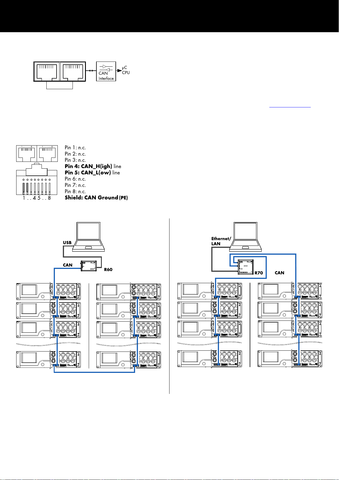
4.3.5. CAN (CAN-Bus)
CAN
The device is equipped with a 2-wire serial remote control interface
carrying the CAN-Bus signals to enable remote control with the
d&b R60 USB to CAN or R70 Ethernet to CAN interfaces.
Note: A detailed description of remote control via the d&b
Remote network (CAN-Bus) is given in the technical
information TI 312 (d&b code D5312.EN) which can be
downloaded from the d&b website at
www.dbaudio.com.
All pins of both connectors are wired in parallel allowing either to
be used as input or output (daisy chaining) or for terminating the
CAN-Bus network.
Pin assignment
The pin assignments of both, the RJ 45 sockets and the cable
connectors, are shown in the graphic opposite.
Note: The connections for the CAN-Bus are referenced to
common ground. The "CAN Ground" is routed via the
cable shielding and is hardwired to PE.
Within the CAN-Bus network, shielded cables and shielded
RJ 45 connectors (metal housing) must be used while the
cable shielding must be connected to both sides.
CAN network topologies
Daisy chain topology
With R60 USB to CAN interface
Combined topology
With R70 Ethernet to CAN interface
d&b D80 Manual 1.9 en 19
Page 20
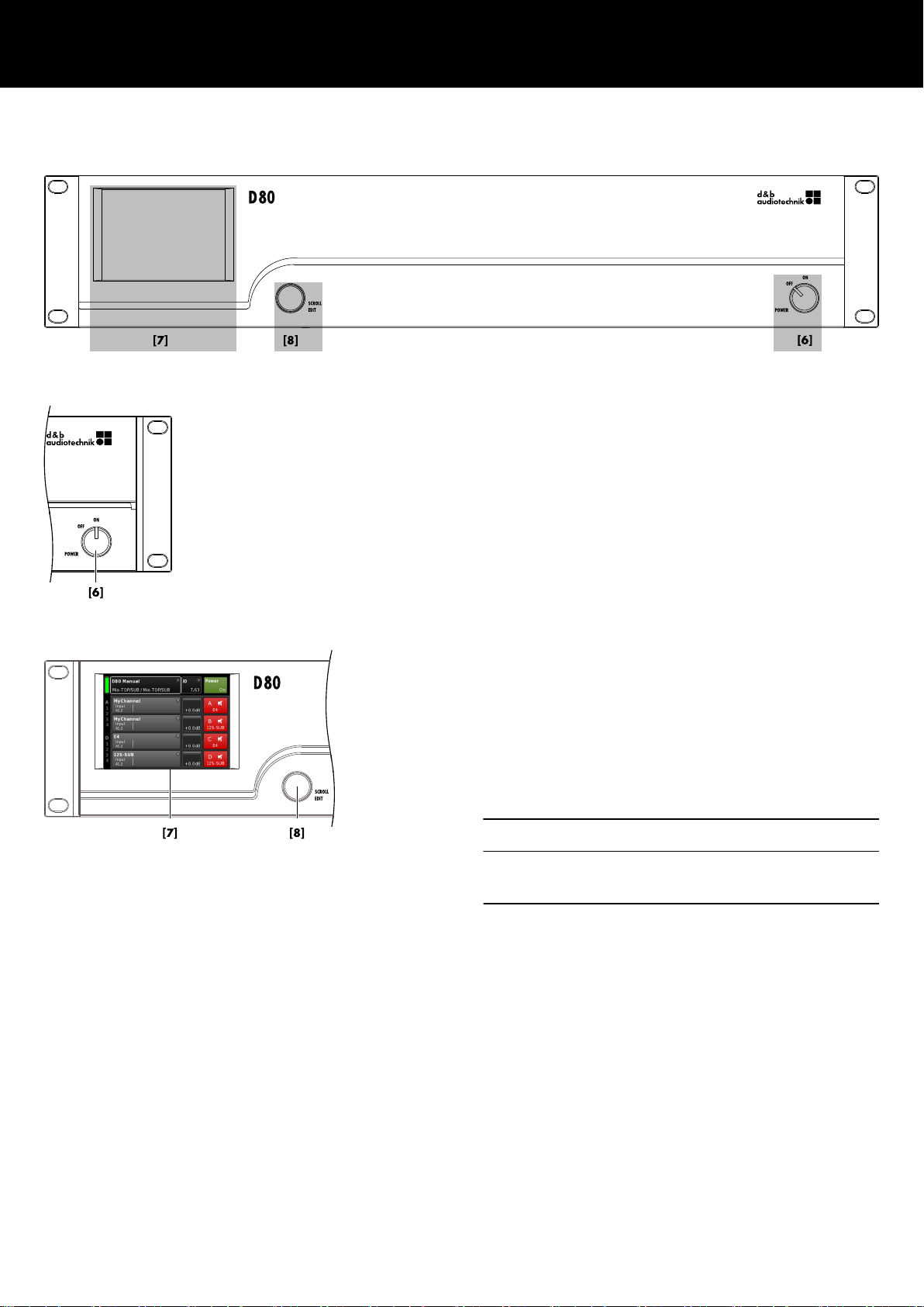
4.4. Controls and indicators
4.4.1. Mains power switch
The on/off rotary switch [6] is located on the bottom right of the
front panel.
OFF
Mains isolation is not provided. The internal power
supplies are off but stay connected to the mains.
ON The unit is switched on and ready for operation.
4.4.2. Display - User interface
Operation, configuration and status viewing are all performed via
the Display Þ User interface.
The user interface consists of a 3.5" TFT color touch screen [7] with
a resolution of 320 x 240 pixels and an additional digital rotary
encoder [8].
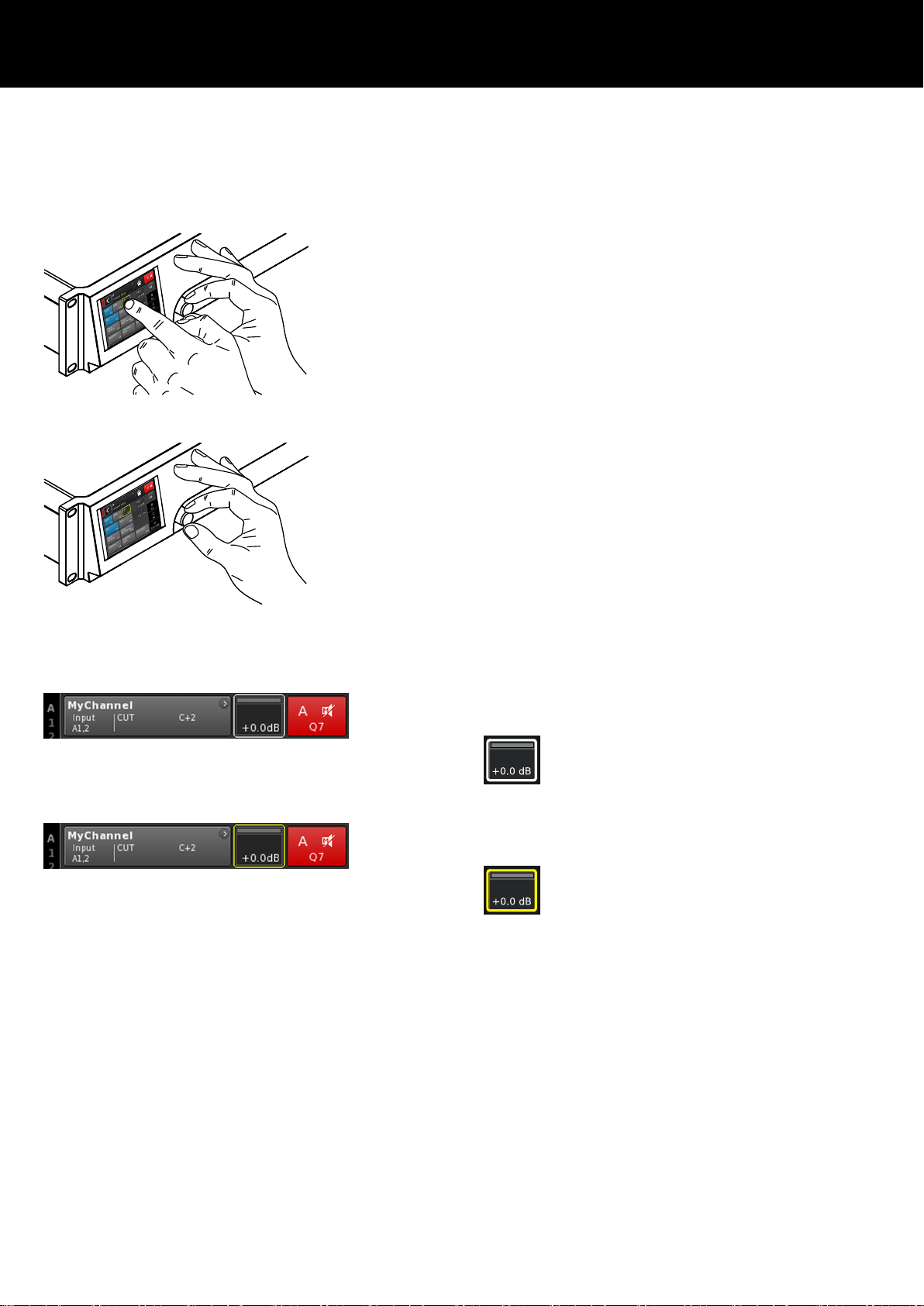
The resistive touch screen responds to pressure and therefore can
be operated by a fingertip, even when wearing gloves, or by an
appropriate stylus tip (pen).
NOTICE!
The touch panel utilizes a thin flexible sheet that may be damaged
by sharp objects or heavy treatment.
Due to the wide range of functions the user interface is described
separately in more detail in Þ Chapter 5. "User interface"
on page 23.
However, both the Standby and Mute functions of the D80 are
described in the following two sections.
d&b D80 Manual 1.9 en20
Page 21
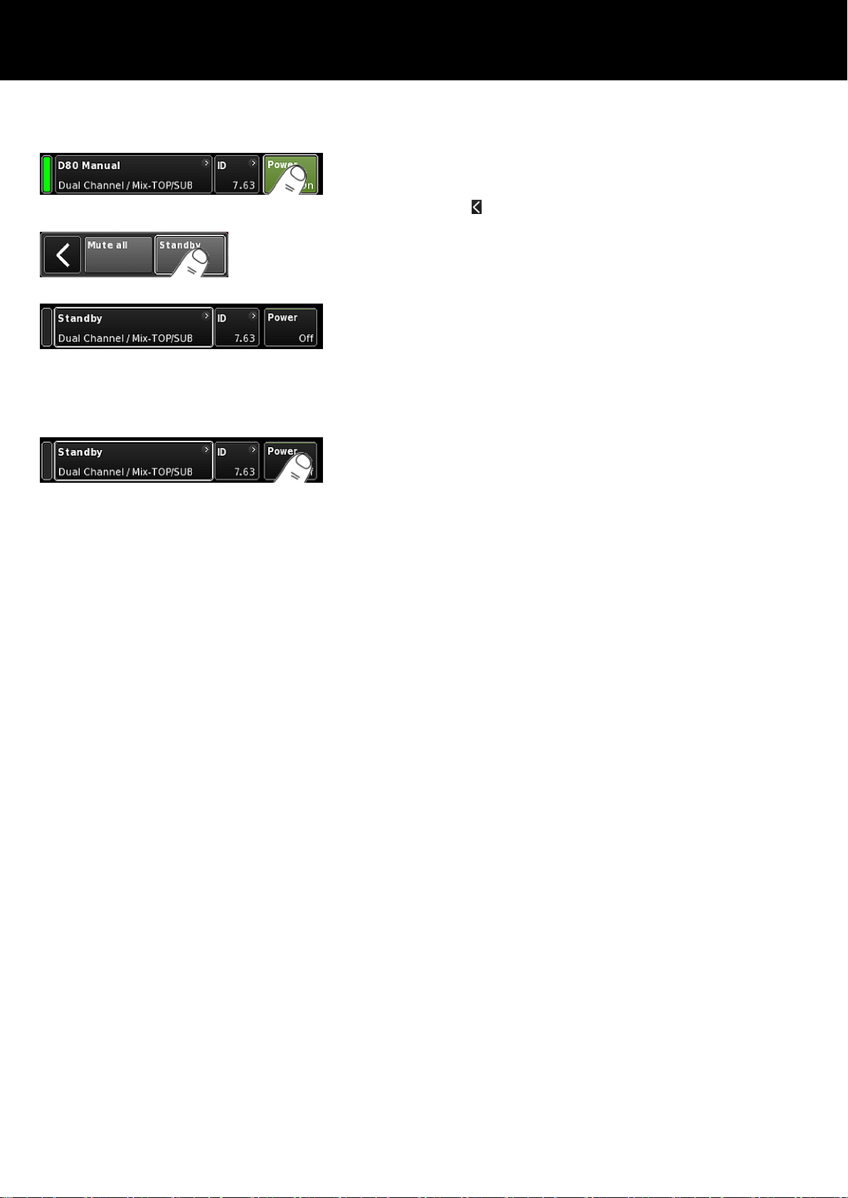
4.4.3. Standby mode
To switch the device to Standby mode ... :
1. Tap the «Power» button on the top right of the Home screen.
A dialog appears allowing you to either select the Back button
( - cancel), «Mute all» or «Standby».
2. Select «Standby».
When the device is in Standby mode, both the «Power» button on
the right and the green Power on indicator on the left are switched
off. In addition, on the Device view button, Standby flashes
alternating with the Device name.
Note: In Standby mode, the user interface of the device is still
operable.
3. To repower the unit, tap the «Power» button.
Startup time from Standby state is < 1 sec.
The operating state (Standby mode) is stored when the «Power»
button is set to "Off" and is restored when the «Power» button is set
back to "On" again.
In Standby mode, the main power supply and the power amplifiers
are switched off to save energy and the loudspeaker outputs are
electronically isolated. The display and controls remain active to
allow repowering of the device by remote control or by tapping
the «Power» button on the Home screen.
Note: When the device is set to Standby (or the mains power
is switched off), the movement of the loudspeaker cones in the
connected cabinets is no longer damped by the power
amplifier output. This removal of the damping makes them
susceptible to excitation by other loudspeakers in the
surroundings. Audible resonances may occur, and even
absorption of low frequency sound energy as the undamped
loudspeakers act like a "bass trap".
To permanently mute single subwoofer cabinets while others
are operated at the same time it is therefore preferable to use
the Mute function instead of Standby. However, the Standby
mode can be useful with mid/high systems as it removes any
residual noise from the system.
d&b D80 Manual 1.9 en 21
Page 22
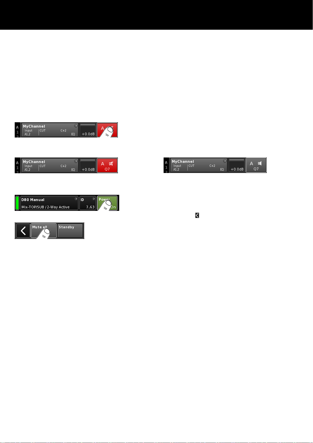
4.4.4. Mute functions
The D80 provides two mute functions:
– Individual mute buttons for each channel or pair of channels
Þ Channel mute,
– and a master mute function Þ «Mute all».
Note: The device stores the setting of the mute buttons when
the mains power is switched off or disconnected. When the
unit is switched on or reconnected, the mute status will be
recalled.
Channel mute
Þ
To mute or unmute a single channel or a pair of channels,
simply tap the respective Channel mute button.
The Channel mute button displays the mute status of the
Þ
relevant channel or pair of channels and the loudspeaker
setup loaded.
Channel muted
Channel unmuted
Master mute («Mute all»)
1. To mute all channels simultaneously, tap the «Power» button
on the top right of the Home screen.
A dialog appears allowing you to either select the Back
Þ
button (
- cancel), «Mute all» or «Standby».
2. Select «Mute all».
To unmute the channels, use the individual Channel mute
Þ
buttons.
d&b D80 Manual 1.9 en22
Page 23
5. User interface
5.1. Operating concept
The operating concept allows different methods of interaction and
configuration.
Touch screen in combination with the rotary encoder
This method may preferably be used to define values of input fields
such as Gain settings, CPL, Delay or EQ settings.
– Select menus, menu items and/or function elements by
tapping the relevant item.
– Enter/edit values by turning the encoder.
– Confirm entered/changed values by tapping the respective
item or confirmation button («OK») or pushing the encoder.
Rotary encoder only
This method is mainly intended for users who are familiar with the
user interfaces of other d&b amplifiers.
– Select menus, menu items and/or function elements by turning
the encoder to move the Position cursor to the relevant item.
– Access the selected item or function element by pushing the
encoder.
– Enter/edit values by turning the encoder.
– Confirm entered/changed values or leave Edit mode by
pushing the encoder.
Cursor conventions
The graphical user interface features two types of cursors, the
Position and the Edit cursors.
Position
cursor
The Position cursor marks the selected Menu item by
a white frame. Depending on the type of screen
item, the Position cursor allows you to either activate
a function, navigate through the menu or enter Edit
mode Þ Edit cursor.
Edit
cursor
In Edit mode, the Edit cursor is marked by a yellow
frame. Turning the encoder to the right (clockwise)
increases the current value, turning the encoder to
the left (counterclockwise) decreases it.
To leave Edit mode press the encoder or simply tap
the respective Menu item again. The color of the
frame will change from yellow back to white again
Þ Position cursor.
d&b D80 Manual 1.9 en 23
Page 24
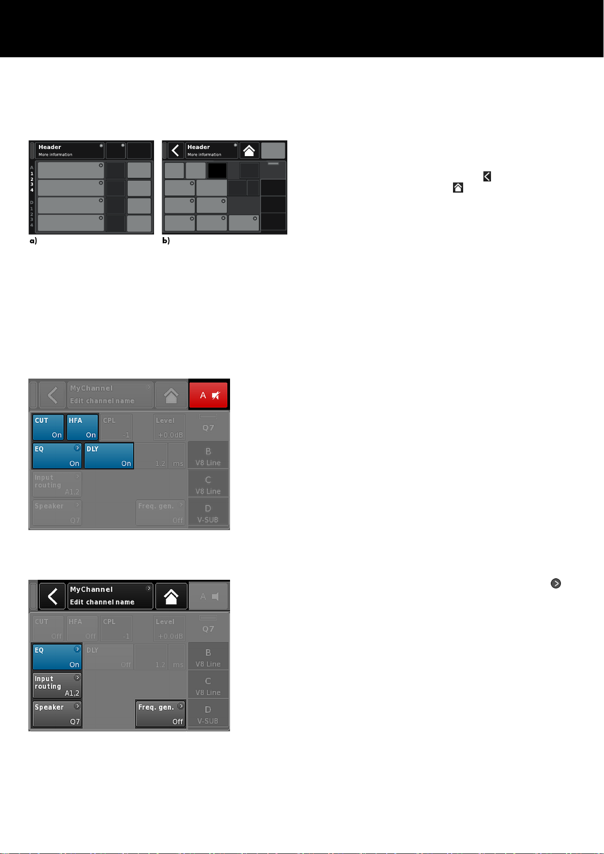
Basic screen layout
a) Home screen
b) Device and Channel setup screens
5.2. Screen layout and conventions
The screen layout is split into two main parts, the Header and the
Data sections.
Header The Header (Headline) indicates which screen is
currently selected. In the Device and Channel setup
screens, the Header allows direct access to the
previous screen (Back button - ) or to the Home
screen (Home button - ).
Data
Except for the Home screen, the Data sections of the
Channel and Device setup screens are structured in
tabs on the right hand side of the screen.
The tabbed structure of the screens allows you to
directly access the desired subscreens.
5.3. Screen items and views
This section describes the different menu items, views and function
elements characterizing the user interface of the D80.
5.3.1. Function buttons
Properties:
– The top left of the button shows the function name while the
bottom right shows the status of the function. In addition, the
status is also indicated by colors.
– The function is activated by tapping the button on screen or
pushing the encoder.
– Functions buttons can also be combined with navigation
buttons.
5.3.2. Navigation buttons
Properties:
– The top right of the button shows the navigation symbol (
– Open the related subscreen by tapping the button on screen
or pushing the encoder.
).
d&b D80 Manual 1.9 en24
Page 25
5.3.3. Input fields
Properties:
– The top left of the button shows the field name while the
bottom right shows the value. The value can be edited.
– Select the value by tapping the button on screen or pushing
the encoder.
– Edit the value by turning the encoder.
Note: The set value will be applied directly.
5.3.4. Input masks
Properties:
– Appears automatically anytime you need to enter data to
define a particular function. The input mask provides you with
an alphanumeric or numeric keypad to enter, for example, a
device name or a channel name (alphanumeric keypad) or an
IP address (numeric keypad).
– Selection and editing is performed using the touch screen or
turning and pushing the encoder.
5.3.5. Information fields
Properties:
Non-selectable/non-editable field for information purposes only.
d&b D80 Manual 1.9 en 25
Page 26

6. Home screen
Home screen access chart
Hierarchy level
From the Home screen, the menu structure of the operating
software is divided into two main axes, the Device setup and the
Channel setup. The navigation buttons allow for direct vertical
access to the specific submenus while the tab structure on the right
side of each submenu provides a clear horizontal order.
In addition, the Home screen gives direct access to the Remote
subscreen.
The Home screen can be accessed from any screen or menu at
any level using the Home button (
).
d&b D80 Manual 1.9 en26
Page 27
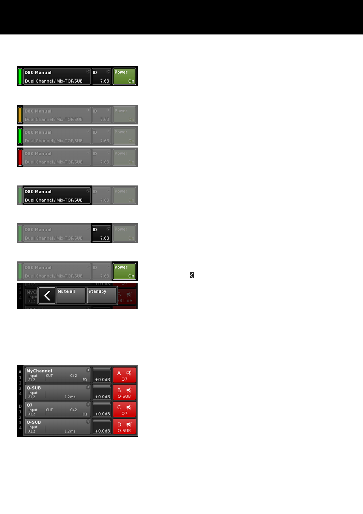
6.1. Header area - Device
(from left to right):
Power on indicator
Yellow Indicates the start up phase of the power supply.
Green Indicates that the unit is switched on.
Red Indicates a device error.
Device view button
The device name and the output mode are displayed. This button
provides direct access to the Device setup screen.
ID
The Remote «ID» is displayed. This navigation button also provides
direct access to the Remote subscreen.
Power button
The «Power» button provides the following functions:
Cancel the sequence.
Mute all Master mute.
To unmute the channels, use the individual Channel
mute buttons.
Standby In Standby mode the device idles drawing minimal
power consumption. Only the most essential
functions are provided. The screen and network
remain functional.
6.2. Data area - Channel strip(s)
The data area features the actual channel strips starting with the
input connector and then following the real signal flow from left to
right. All vital information is displayed. This includes:
– Input signal present (ISP)
– Input routing
– Channel configuration,
– Controller output signal (OSP)
– Channel mute buttons and status.
– Error messages
d&b D80 Manual 1.9 en 27
Page 28
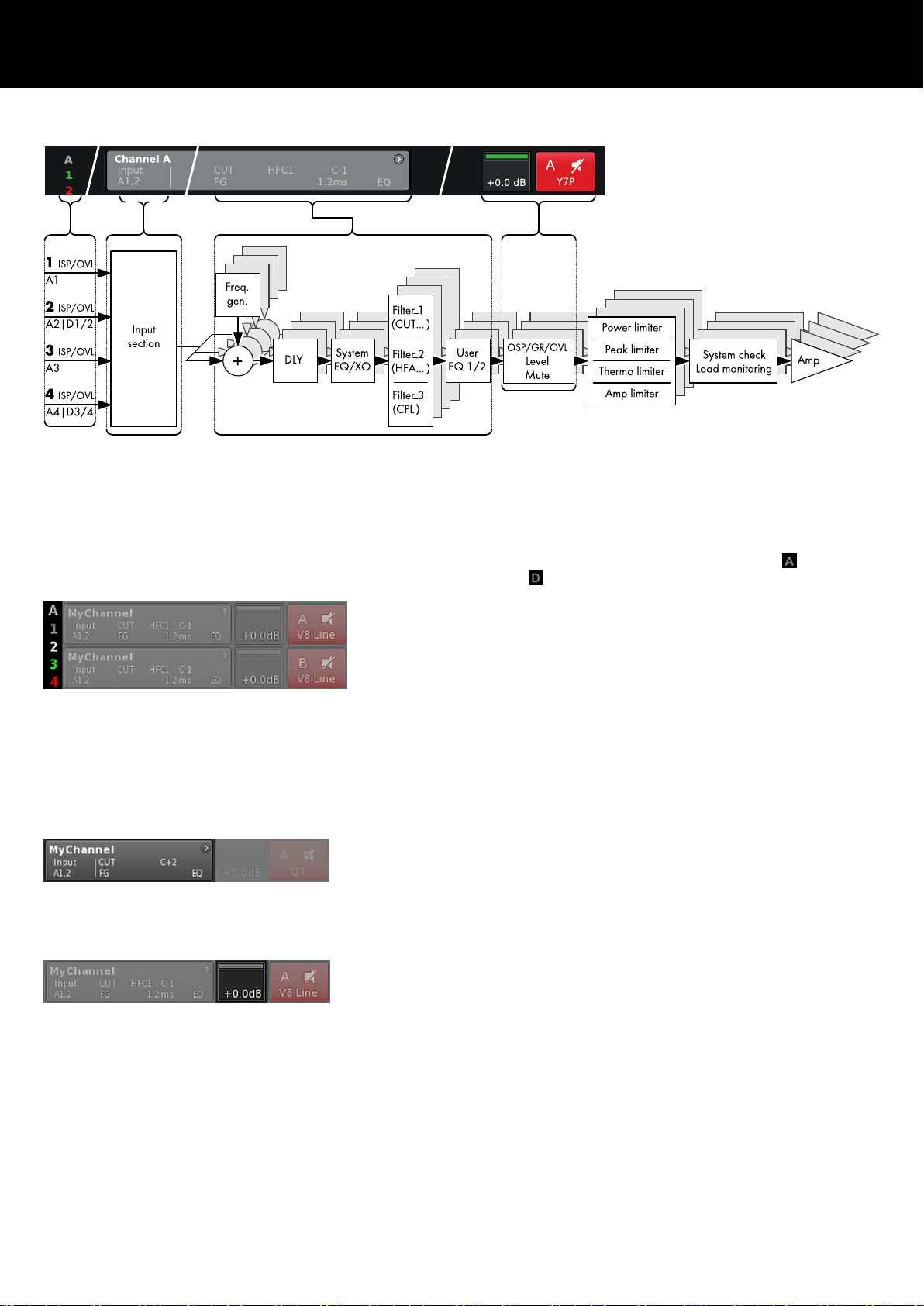
7. Channel strip
D80 Channel strip block diagram (signal chain)
The channel strip follows the actual signal chain from left to right:
ISP/OVL
Indicates the following states for both, the analog ( ) and the
digital ( ) signal inputs:
Grey
The relevant channel is not available.
White The relevant channel is available and an input signal is
not present or below –30 dBu.
Green ISP (Input Signal Present): Illuminates when the
analog input signal exceeds –30 dBu or when the
digital input is locked to 48 or 96 kHz and the signal
exceeds –57 dBFS.
Red
OVL (Overload): Illuminates when the analog input
signal exceeds 25 dBu or when the digital input signal
exceeds –2 dBFS.
Channel view
The Channel view button displays the Channel name. If no
Channel name has been entered, the loudspeaker setup which is
currently loaded is displayed. In addition, the activated function
elements are indicated. The button provides direct access to the
Þ Channel setup screen.
Level
The Level input field allows direct setting of the amplifier's relative
input sensitivity in the range of –57.5 dB to +6 dB in steps of
0.5 dB.
In addition, the following indicators are available:
d&b D80 Manual 1.9 en28
Page 29

ISP/OSP/GR/OVL
Indicates whether the DSP receives an input signal and whether the
DSP output signal is present (provided the channel is not muted).
Grey No signal present.
Dark
Channel input signal present (ISP).
green:
Bright
Controller (DSP) output signal present (OSP).
green:
Yellow GR (Gain Reduction):
Illuminates when one limiter reduces the signal by a
predefined level (GR ³ 3 dB).
Red OVL (Overload):
Illuminates when ...:
– any signal within the channel exceeds
–2 dBFS.
– DSP suffers from an internal EQ filter overflow.
– any limiter causes a gain reduction of 12 dB
or more.
– the output signal is limited to prevent distortion
due to output peak current overload of >70 A.
Channel muted
Channel mute
Þ
To mute or unmute a single channel or a pair of channels,
simply tap the respective Channel mute button.
The Channel mute button displays the mute status of the
Þ
relevant channel or pair of channels and the loudspeaker
setup loaded.
Channel unmuted
A channel error is indicated on the Channel mute button by an
exclamation mark Þ .
A corresponding error message is issued on the Channel view
button.
d&b D80 Manual 1.9 en 29
Page 30

8. Basic settings - Quick reference
Due to the vast functional range and possible settings of the D80
amplifier, this section is intended as a quick reference to provide
you with a systematic procedure for defining the basic settings of
the amplifier.
It is advisable to start with the device settings followed by the
individual channel settings.
System reset
Before starting to define the basic settings, perform a system reset.
1. Switch off the device.
2. Press and hold the encoder and repower the device.
Long confirmation beep.
Þ
3. Release the encoder and briefly press the encoder again
within 2 sec.
Short confirmation beep.
Þ
The device will boot up and will switch to the Home
screen. A corresponding message will be issued:
1. Device setup
Þ
On the Home screen, tap the Device view button.
This will enter the Device setup subscreen with the «Input»
Þ
tab being active.
2. Input (Input mode / Input routing)
Þ
Define your Input mode and Input routing settings for all
channels correspondingly.
Note: A detailed description of the Input routing is given in
the reference chapter of the Channel setup Þ Chapter 10.6.
"Input routing" on page 56.
A detailed description of the Input mode is given in the
reference chapter Þ Chapter 9.2. "Input" on page 34.
3. Output (Output mode)
Þ
Tap the «Output» tab and define your desired output mode
settings for each pair of amplifier channels correspondingly.
Note: A detailed description of the available output modes is
given in the reference chapter Þ Chapter 9.3. "Output"
on page 36
d&b D80 Manual 1.9 en30
Page 31

Speaker
1. On the bottom left of the «Output» tab, select the «Speaker»
navigation button to enter the Speaker setup subscreen.
2. Choose the desired speaker setups for all channels and
confirm each selected setup by tapping the «OK» button right
next to the «Speaker» selection field.
3. Define the LoadMatch settings, if applicable and desired,
correspondingly.
4. After defining all settings, exit the subscreen by tapping the
Home button (
).
Note: A detailed description of the Speaker setup and
LoadMatch settings is given in the reference chapter
Þ Chapter 10.8. "Speaker" on page 59.
4. Remote
1. On the Home screen, tap the Device view button to enter the
Device setup menu.
2. Tap the «Remote» tab and define your desired Remote settings
correspondingly.
Note: A detailed description of the remote settings is given in
the reference chapter Þ Chapter 9.4. "Remote"
on page 41.
As all the configurations and settings mentioned above can
also be defined remotely, it depends on how you wish to
proceed whether defining the Remote settings is the last or the
first step when configuring your basic settings.
After defining all settings, exit the subscreen by tapping the Home
button (
) and carry on with the individual channel settings.
5. Channel setup
1. On the Home screen, tap the Channel view button of the first
channel (A) or pair of channels (A/B) to enter the Channel
setup.
2. Define your individual channel settings such as CUT, HFA,
CPL, Level, DLY or EQ for all channels correspondingly.
3. After defining all settings, exit the subscreen by tapping the
Home button (
).
Note: A detailed description of the Input routing is given in
the reference chapter Þ Chapter 10.6. "Input routing"
on page 56.
A detailed description of the Input mode is given in the
reference chapter Þ Chapter 9.2. "Input" on page 34.
d&b D80 Manual 1.9 en 31
Page 32

9. Device setup
Device setup access chart
Hierarchy level
d&b D80 Manual 1.9 en32
Page 33

From the Home screen, selecting the Device view button opens the
Device setup screen with the «Input» tab being active.
The Device setup screen follows the same layout structure as
described above and is split into the Header and the Data
sections.
Using the tabbed structure of the Device setup screen provides
direct access to the desired subscreens.
9.1. Device name
Selecting the centered Information field button
(«Edit device name») in the header of the device setup screen
enables you to enter or edit the device name (maximum length 15
characters).
The input mask which appears allows either lower-case or uppercase characters by toggling the corresponding button («abc») on
the bottom left.
Wrong entries can be corrected by tapping the Erase button (
on the bottom right.
Tapping «OK» on the top right confirms the entry, closes the input
mask and switches back to the Device setup screen.
Tapping the Back button (
) on the top left cancels any entry and
switches back to the Device setup screen keeping the previous
entry.
)
d&b D80 Manual 1.9 en 33
Page 34

9.2. Input
Selecting the «Input» tab allows you to configure the Input mode
for the input connector pairs 1/2 and 3/4 independently to accept
either analog or digital input signals.
The operating mode of the corresponding link output connectors 2
and 4 depends on the set input mode.
9.2.1. Input mode
Input mode block diagram
Analog/Analog
Both input connector pairs ½ and 3/4 are set to «Analog», an
analog audio signal is accepted by inputs 1, 2, 3 and 4.
d&b D80 Manual 1.9 en34
Page 35
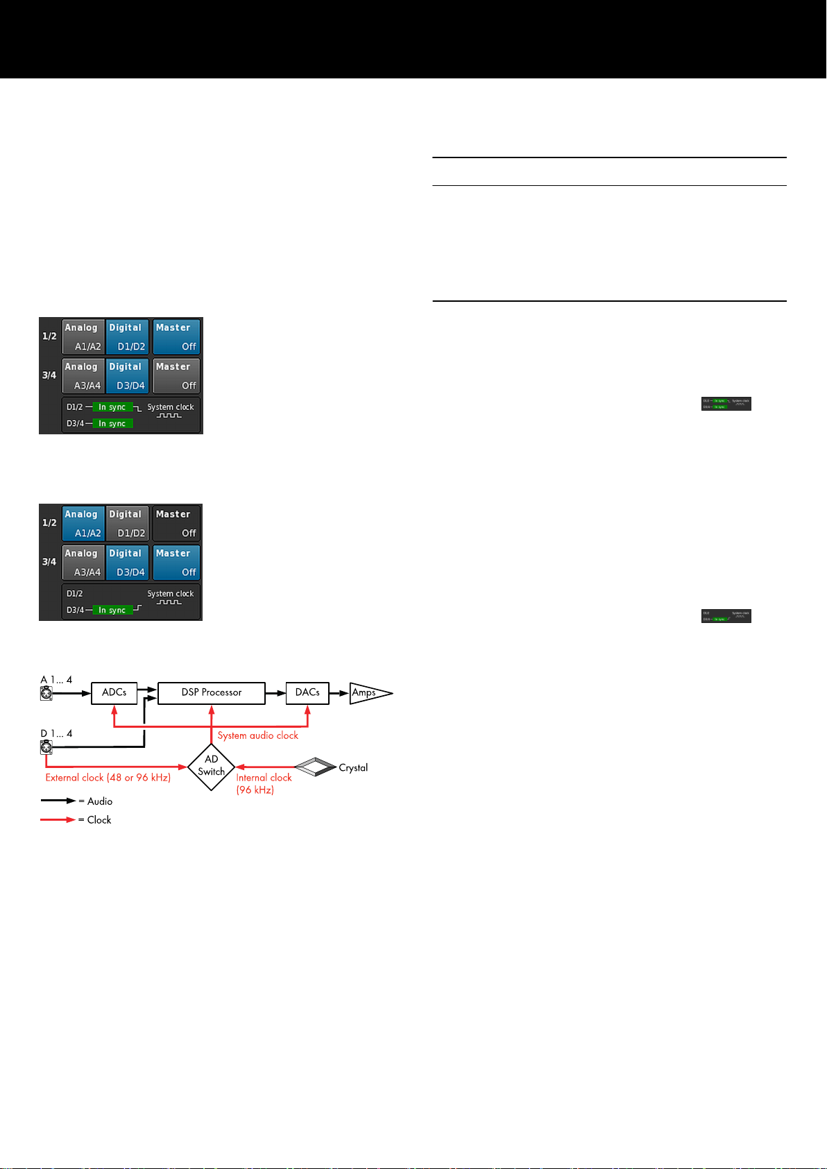
Digital/Digital
NOTICE!
When both input pairs are set to «Digital» and locking to the sync
source is not possible, none of the inputs will receive any audio
signal.
If two digital signals are used at the same time, these signals must
be completely synchronous (i.e. must have the same synchronized
sampling rate).
Both input connector pairs ½ and 3/4 are set to «Digital», a 2channel digital audio signal is accepted by inputs 2 and 4
respectively.
The input connectors 1 and 3 are not available.
Locking to either 48 or 96 kHz is indicated below (
). In
this case, the sync source is input 2.
When both input pairs are set to «Digital», either of them can be
selected as sync source.
Mixed
Input connector pair 1/2 is set to «Analog», an analog 2-channel
audio signal is accepted by inputs 1 and 2.
Input connector pair 3/4 is set to «Digital», a digital 2-channel
audio signal is accepted by input 4.
A3 by input 3 is not available.
Locking to either 48 or 96 kHz is indicated below (
). In
this case, the sync source is input 4.
Clocking
To keep latency as short as possible, the system does not utilize
non-clocked (asynchronous) Sample Rate Converters (SRC).
The clock of the digital audio system is derived from an internal
crystal oscillator with a sampling rate of 96 kHz. Alternatively, the
clock can be derived from a signal fed to the digital inputs. The
sampling rate of this signal must also be 96 kHz. The derived clock
is PLL filtered to avoid possible jitter.
It is also possible to use a signal with a sampling rate of 48 kHz as
it is in even proportion to the required 96 kHz. In this case, the
system detects the sampling rate and automatically doubles it using
a synchronous sampling rate doubler to achieve the required
96 kHz. The required filtering is calculated using linear phase FIR
filters.
d&b D80 Manual 1.9 en 35
Page 36

9.3. Output
Selecting the «Output» tab allows you to assign the appropriate
Output mode to a pair of amplifier output channels (AMP A/B
and/or AMP C/D).
The following Output modes can be assigned to a pair of amplifier
output channels (AMP A/B and/or AMP C/D).
– Dual Channel
– Mix TOP/SUB
– 2-Way Active
– Mixed configurations
Þ
A change of the Output mode must be confirmed. This is done
by selecting either the Back ( ) or the Home ( ) button.
The set Output mode will be activated and the
Þ
corresponding channels will be muted.
Note: Changing the Output mode directly affects the
available range of loudspeaker setups.
On the Home screen, the selected Output mode is displayed in the
header area below the device name.
2 x Dual Channel
2 x Mix TOP/SUB
The channel strips below the Header section change depending on
the chosen modes as shown below.
2 x 2-Way Active
Mixed configuration
On the bottom left of the Output screen, the «Speaker» navigation
button provides direct access to the Þ Speaker setup screen.
d&b D80 Manual 1.9 en36
Page 37

9.3.1. Output mode
NOTICE!
Ensure that the connected loudspeaker type corresponds to the
actual output configuration of the D80.
Dual Channel mode (A/B, C/D)
The Dual Channel mode is dedicated to d&b fullrange systems
(passive systems) and actively driven d&b subwoofers. Both
channels of each pair of amplifier channels can be configured for
TOP or SUB cabinets independently.
In Dual Channel mode each pair of amplifier output channels
(AMP A/B, AMP C/D) acts as a two channel amplifier (stereo
amplifier). The amplifier channels are connected to their
corresponding output connectors (AMP A to OUT A ...) while the
audio input for each amplifier channel can be assigned via the
input routing.
Each output connector is wired in parallel using the respective pins
for TOP or SUB configurations.
Pin equivalents of NL4 and EP5 connectors in relation to the output
mode are listed in the table below.
2 x Dual Channel mode
NL4
SPEAKER OUTPUTS A (B, C, D):
1+/2+ = Amp A (B, C, D) pos.
1—/ 2— = Amp A (B, C, D) neg.
EP5 SPEAKER OUTPUTS A (B, C, D):
1/3 = Amp A (B, C, D) pos.
2/4 = Amp A (B, C, D) neg.
5 = n.c.
d&b D80 Manual 1.9 en 37
Page 38

Mix TOP/SUB mode (A/B MIX, C/D MIX)
The Mix TOP/SUB mode allows d&b fullrange systems (passive
systems) and actively driven d&b subwoofers to be linked together
and connected to the amplifier using a single 4-wire cable.
TOP cabinets (setups) can be selected on channel A (C) and SUB
cabinets (setups) on channel B (D).
In Mix TOP/SUB mode both amplifier channels of the
corresponding pair (AMP A/B, AMP C/D) are connected to both
output connectors (AMP A and AMP B to OUT A and OUT B ...)
while the audio input for each amplifier channel can be assigned
via the input routing.
Two output connectors (A/B, C/D) are wired in parallel using the
respective pins for TOP and SUB configurations.
Pin equivalents of NL4 and EP5 connectors in relation to the output
mode are listed in the table below.
2 x Mix TOP/SUB mode
NL4
EP5
SPEAKER OUTPUTS A/B (C/D):
1+ = Amp A (C) pos. (TOP)
1— = Amp A (C) neg.(TOP)
2+ = Amp B (D) pos. (SUB)
2— = Amp B (D) neg. (SUB)
SPEAKER OUTPUTS A/B (C/D):
1 = Amp A (C) pos. (TOP)
2 = Amp A (C) neg. (TOP)
3 = Amp B (D) pos. (SUB)
4 = Amp B (D) neg. (SUB)
5 = n.c.
d&b D80 Manual 1.9 en38
Page 39

2-Way Active mode (2-WAY)
The 2-Way Active mode is dedicated to d&b active systems.
In 2-Way Active mode both amplifier channels of the
corresponding pair (AMP A/B, AMP C/D) are connected to both
output connectors (AMP A and AMP B to OUT A and B ... ). The
audio input for each pair of amplifier channels can be assigned via
the input routing.
All settings of channel A (C) and the corresponding input signal
are internally linked to channel B (D).
Pin equivalents of NL4 and EP5 connectors in relation to the output
mode are listed in the table below.
2 x 2-Way Active mode
NL4
EP5
SPEAKER OUTPUTS A/B (C/D):
1+ = Amp A (C) pos. (LF)
1— = Amp A (C) neg.(LF)
2+ = Amp B (D) pos. (MF/HF)
2— = Amp B (D) neg. (MF/HF)
SPEAKER OUTPUTS A/B (C/D):
1 = Amp A (C) pos. (LF)
2 = Amp A (C) neg. (LF)
3 = Amp B (D) pos. (MF/HF)
4 = Amp B (D) neg. (MF/HF)
5 = n.c.
d&b D80 Manual 1.9 en 39
Page 40

Mixed configurations
As the output mode is assigned to a pair of amplifier channels
(AMP A/B, AMP C/D) mixed configurations such as ...:
– AMP A/B Þ Dual Channel, AMP C/D Þ 2-Way Active
– AMP A/B Þ Dual Channel, AMP C/D Þ Mix TOP/SUB
– AMP A/B Þ Mix TOP/SUB, AMP C/D Þ 2-Way Active
... as well as all other combinations are also possible.
Mixed configuration example
AMP A/B Þ Dual Channel, AMP C/D Þ 2-Way Active
d&b D80 Manual 1.9 en40
Page 41

9.4. Remote
Selecting the «Remote» tab allows you to assign remote settings for
both Ethernet and CAN remote control.
Selecting the navigation field «IP settings» enters the corresponding
subscreen. In addition the IP mode is displayed at the bottom right
of the field.
9.4.1. IP settings IP address IP mask IP gateway
Selecting either field opens the numerical input
mask and allows you to enter the relevant
data.
Wrong entries can be corrected by tapping
the Erase button ( ) on the bottom right.
Tapping «OK» on the top right confirms the
entry, closes the input mask and switches back
to the Remote screen.
Tapping the Back button (
) on the top left
cancels any entry and switches back to the
Remote screen keeping the previous entry.
Set gateway
to default
Selecting this button the gateway adress will
be derived from the IP adress and IP mask
settings.
IP mode Selecting the field allows the following settings:
Auto
(DHCP)
When the device is connected
to a network with a DHCP
server present, a matching IP
address will be assigned
automatically.
Manual
Allows the manual assignment
of IP settings.
Additional information fields
MAC:
Displays the fixed MAC address of the device.
Conn.: Shows which of the etherCON connectors is
connected (busy).
Status: Provides status information on the network.
d&b D80 Manual 1.9 en 41
Page 42

9.4.2. Remote ID
Selecting the «Remote ID» button allows the setting of the unique
Remote identifier of the respective device in the format [nn].[nn].
Subnet The first two digits represent the subnet.
Within an Ethernet network up to 100
subnets can be defined (values 0 to 99).
Within a CAN network up to eight subnets
can be defined (values 0 to 7).
Note: In case of a Subnet mismatch the
following message is issued at the bottom
of the screen:
Remote ID exceeds 7.63, CAN disabled!
Device ID Using the two digit device ID for each subnet,
you can define a total of 63 devices (values 1
to 63).
9.5. More
Selecting the «More» tab provides further subscreens such as:
– Preferences
– Info
– Levels
– Mains current limiter
– ...
9.5.1. Preferences
Selecting «Preferences» opens the corresponding subscreen with
the «Display» tab being active.
d&b D80 Manual 1.9 en42
Page 43

9.5.1.1. Display
The «Display» tab provides the following display options.
Backlight
Enables the following optional settings:
Off The display brightness is set to 1 (minimum
brightness).
On The backlight is permanently on.
Timeout
10s
The display is illuminated when the encoder is
pressed or when the display is touched. The light
switches off automatically 10 seconds after the
last operation.
Note: This setting is recommended to increase the lifetime of
the display.
Brightness
Enables adjustment of the display brightness in the range from 1 to
10. The default setting is 8.
Touch beep
Enables or disables the beep sound when using the touch screen.
Touch screen calibration
Due to mechanical impact or the aging process of the touch
screen, its calibration references may change.
An indication is that when you tap a specific button and the
adjacent button is activated instead or when ap specific button
does no longer work.
In such cases, the touch screen should be recalibrated.
To calibrate the touch screen, proceed as follows:
1. Select «Touch screen calibration».
The Screen calibration menu will open guiding you
Þ
through the calibration process.
2. Follow the relevant on-screen instructions.
9.5.1.2. Lock
Selecting the «Lock» tab opens the corresponding subscreen which
enables different protection settings.
Mode
Selecting «Mode» toggles between two options to protect the
device against unintentional operation.
Press knob 2s
Prevents accidental operation by locking the
front panel controls.
Password Enables password protection to prevent
operation by unauthorized persons.
Screen
Selecting «Screen» allows two different settings for the screen
when the device is locked.
d&b D80 Manual 1.9 en 43
Page 44

Home screen Switches to the Home screen.
Levels Switches to the Levels screen.
Edit password
Selecting the «Edit password» option opens an input mask which
enables you to edit or assign a password (upper-case characters
with a maximum length of 7 characters).
Wrong entries can be corrected by tapping the Erase button on the
bottom right (
).
Tapping «OK» on the top right confirms the entry, closes the input
mask and switches back to the Lock screen.
Tapping the Back button ( ) on the top left exits the input mask
and leaves the previous password unchanged.
Note: The factory default password is: DBAUDIO
Lock
Tapping the «Lock» button confirms any new settings and exits the
subscreen. A corresponding message is displayed.
The device will be switched to the screen selected for Lock mode.
Unlocking the device
If you attempt to change the status of the device while it is in Lock
mode, the following message will be issued: Press encoder for 2s
to unlock. To unlock the device, proceed as follows:
Press ...
Press and hold the encoder for a minimum of 2
seconds until the message disappears.
Password 1. Press and hold the encoder for a minimum of
2 seconds until the corresponding input mask
is displayed.
2. Enter the password as described above.
An incorrectly entered password will revert the
device to the screen displayed for Lock mode.
If the password is lost or forgotten, a locked device can be
unlocked by performing a system reset.
d&b D80 Manual 1.9 en44
Page 45
Note: All device preferences will be set to factory defaults
except for the network (CAN/Ethernet) and fixed device
settings.
If you execute this procedure, no dialog will be prompted and
the reset will start immediately.
1. Switch off the device.
2. Press and hold the encoder and repower the device.
Long confirmation beep.
Þ
3. Release the encoder and briefly press the encoder again
within 2 sec.
Short confirmation beep.
Þ
The device will boot up and will switch to the Home
screen. A corresponding message will be issued:
9.5.1.3. Preferences/More
Selecting the «More» tab opens the corresponding subscreen
which provides the following options.
Buzzer
Enables the following settings:
Off
The internal buzzer is switched off.
On The internal buzzer is switched on and serves as an
acoustic signal in case of a device or channel error.
Single The internal buzzer generates an intermittent single
tone.
Melody The internal buzzer generates a predefined sequence
of tones.
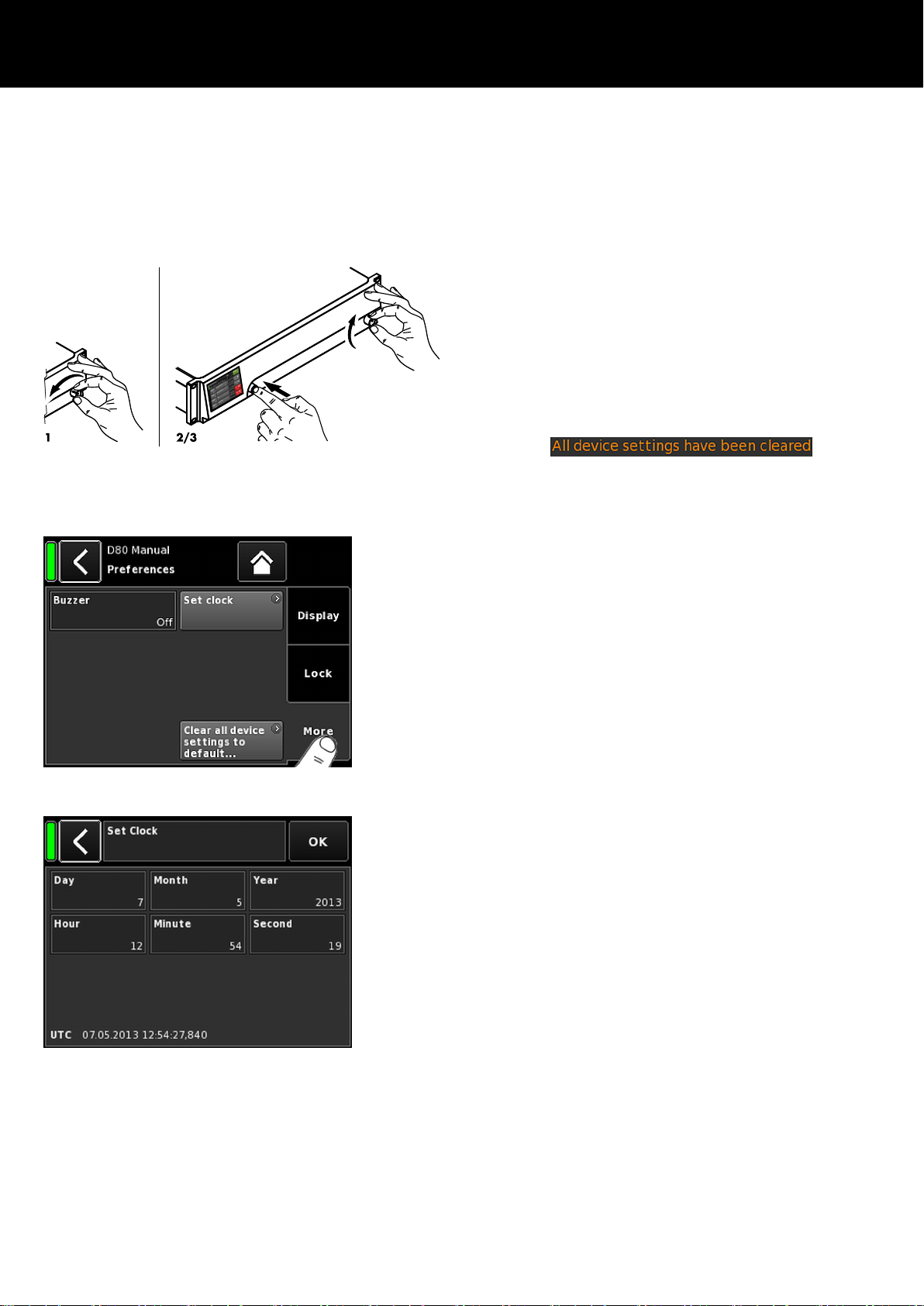
Set clock
Enables setting the internal clock while the current UTC
(Coordinated Universal Time) date and time are displayed at the
bottom of the screen.
Within a Remote network, the device's clock is synchronized with
the connected PC.
d&b D80 Manual 1.9 en 45
Page 46

9.5.1.3.1. System reset
Selecting «Clear all device settings to default» resets all device
settings to factory defaults except for the network (CAN/Ethernet)
and fixed device settings.
To prevent accidental reset when you tap the «Clear...» button, a
dialog will pop up prompting you to confirm the reset or cancel the
sequence by tapping the Back button ( ).
Alternative procedure
A system reset can also be triggered as follows:
Note: All device preferences will be set to factory defaults
except for the network (CAN/Ethernet) and fixed device
settings.
If you execute this procedure, no dialog will be prompted and
the reset will start immediately.
1. Switch off the device.
2. Press and hold the encoder and repower the device.
Long confirmation beep.
Þ
3. Release the encoder and briefly press the encoder again
within 2 sec.
Short confirmation beep.
Þ
The device will boot up and will switch to the Home
screen. A corresponding message will be issued:
9.5.2. Info
Selecting «Info» provides basic information about the device.
The information provided is mainly intended for service purposes.
Most of the information is static information, for example:
– Various firmware versions (Firmware Core/DSP/PS/AMP)
– Serial number
– Owner
In addition, there is dynamic information about the actual
temperatures of... :
– Power supply (Temp. PS)
– The entire power amplifier (Temp. AMP)
– Central Processing Unit (Temp. CPU)
d&b D80 Manual 1.9 en46
Page 47
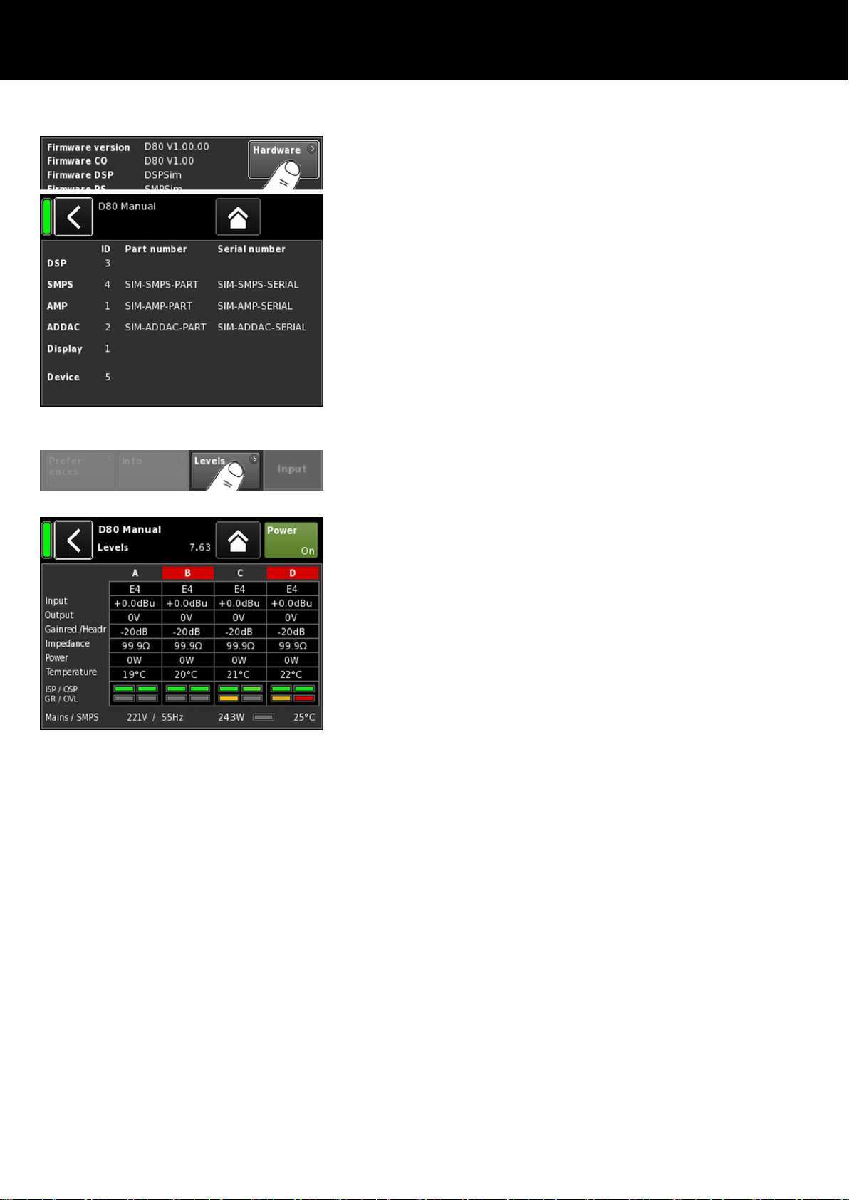
Tapping the «Hardware» button provides further hardware specific
information.
9.5.3. Levels
Selecting «Levels» opens the corresponding subscreen.
The data area of the levels screen provides the following
information (starting at the top left):
1st line
Mute status of each channel.
2nd line Loudspeaker setups selected for the individual
channels.
Input Current input signal levels of the individual
channels.
Output Current output voltages of the individual
amplifier channels.
Gainred/
Headr
Relationship between headroom (Headr) and
gain reduction (Gainred) with peak hold for
1 sec.
Display ranges:
Gainred 0 dB Þ +32 dB.
Headr –32 dB Þ 0 dB.
Impedance Current load impedance values for the
individual amplifier channels.
Power Power currently delivered by the individual
amplifier channels.
Temperature Current temperatures of the individual amplifier
channels.
ISP/OSP Indicates whether the input signal (ISP) as well
as the controller output signal (OSP) of the
individual channel are present.
d&b D80 Manual 1.9 en 47
Page 48
GR/OVL Indicates whether gain reduction (GR) of the
respective channel is active or the respective
channel is overloaded (OVL).
Mains/SMPS Displays the current mains voltage and
frequency, the current mains power
consumption in combination with a power
limiter LED and the current temperature of the
switched mode power supply (SMPS).
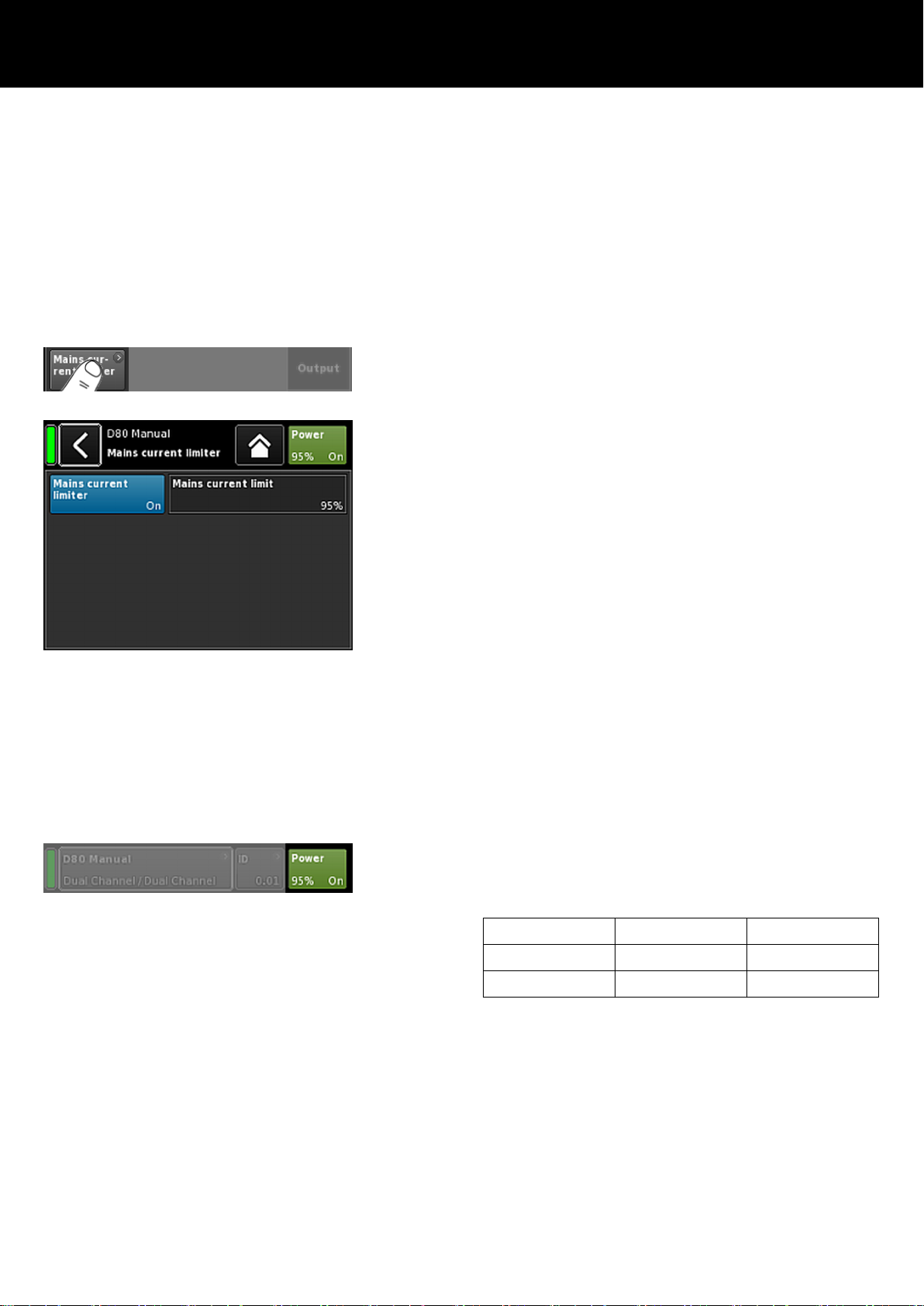
9.5.4. Mains current limiter (MCL)
Selecting «Mains current limiter» opens the corresponding
subscreen.
The D80 features a power limiter which serves to limit the mains
current draw whenever the mains current draw threatens to trigger
the circuit breaker.
Limiting is done by reducing the sound levels evenly on all
channels. This ensures that the tonal balance is kept.
The Mains Current Limiter function allows to set the maximum
mains current draw of the device within the range of 95 to 50 % of
the nominal limit.
The Nominal current limit depends on the mains voltage range:
16 A in high range, 30 A in low range
This may be useful when the onsite conditions require two devices
to be operated per phase conductor or if the onsite circuit breaker
is not sufficiently dimensioned.
On/Off
Mains
current limit
Activates the additional limiter.
The maximum mains current draw is defined as
a percentage value of the nominal current
limit, as indicated above and can be set in the
range from 95 % down to 50 % in steps of
5 %.
When the MCL is activated, the defined value is permanently
displayed on the «Power» button on the Home screen.
Setting recommendations
No. of devices
Circuit breaker MCL setting
1 x D80 13 A @ 230/240 V 80 %
2 x D80 16 A @ 230/240 V 50 %
d&b D80 Manual 1.9 en48
Page 49

9.5.5. AmpPresets
d&b amplifiers provide AmpPresets which contain all important
user settings of the entire device, such as input, output and channel
configurations, EQ and delay settings.
Using AmpPresets, a sound system can be operated in different
configurations (e.g. "Conference", "Music" or "Emergency Call")
without the need of transferring all detailed settings of the devices
used.
There are three types of AmpPresets memories (slots):
User: Nine (9) AmpPresets which can be accessed locally
or via the d&b Remote network. These presets are
used to set the complete device to a previously
defined configuration for a particular application.
They can be named individually.
Alarm:
Three AmpPresets which can only be accessed via
the d&b Remote network. Intended for use in alarm
systems to protect the system settings against local
modifications.
Backup:
Three AmpPresets which can only be accessed via
the d&b Remote network. Intended for temporary use
to back up the current system settings when another
AmpPreset is loaded.
Selecting «AmpPresets» opens the corresponding subscreen which
provides the functions «Select», «Name», «Recall», «Store» and
«Clear».
At the bottom of the screen, the last AmpPreset number loaded is
indicated. If any setting has been modified since loading,
«(modified)» will be added to the corresponding entry.
Select:
Provides access to the nine (9) user preset memories
(slots) for loading, saving or clearing data.
Name: Enables the assignment or editing of a preset name
(maximum of 15 characters).
The input mask which appears allows either lower-case
or upper-case characters by toggling the
corresponding button («abc») on the bottom left.
– Wrong entries can be corrected by selecting the
Erase button (
) on the bottom right.
– Selecting «OK» on the top right confirms the entry,
closes the input mask and switches back to the
AmpPresets screen.
– Selecting the Back button (
) on the top left
cancels any entry and switches back to the
AmpPresets screen keeping the previous entry.
d&b D80 Manual 1.9 en 49
Page 50

Recall: Recalls the settings of a stored preset.
Store: Stores the current amplifier settings to the selected
preset memory.
Clear: The selected preset memory is cleared and «(empty)»
is displayed on the «Name» button.
Note: Choosing one of these functions, a corresponding
confirmation dialog will be issued to allow either confirmation
of the selection or to cancel the action by selecting the Back
button (
).
9.5.6. Scope
The «Scope» function allows basic signal monitoring of the
amplifier's output voltage (full color) and output current (light
color).
Select
A U, I
Output voltage and current of channel A.
B U, I Output voltage and current of channel B.
C U, I Output voltage and current of channel C.
D U, I Output voltage and current of channel D.
All U Output voltage of all channels.
All I Output current of all channels.
All U, I Output voltage and current of all channels.
Y scale
Scale of the measuring values in FS (Full Scale). 1.0 FS represents
the maximum output voltage or output current.
Application examples
The scope function is a useful tool for ...:
– determining the signal quality.
– determining a phase shift between the channels.
– getting a rough impression of the crest factor.
– checking the output channels (e.g. no output current
displayed Þ the connector cable may be interrupted or
no loudspeaker is connected.
– checking the power amplifier (e.g. no output voltage
displayed).
d&b D80 Manual 1.9 en50
Page 51

10. Channel setup
Channel setup access chart
Hierarchy level
d&b D80 Manual 1.9 en 51
Page 52

Selecting a particular channel from the Home screen opens the
corresponding Channel setup screen with the respective Channel
tab being active.
The Channel setup screen follows the same layout structure as
described above and is split into the Header and the Data
sections.
Using the tabbed structure of the Channel setup screen provides
direct access to the desired function element of each channel.
In addition, the «Channel mute» button of the selected channel as
well as the "OSP", "GR" and "OVL" indicators for each channel are
available. This allows you to maintain the integrity of the gain
structure within the unit while setting up the user definable EQ as
well as keeping an eye on the Input routing.
10.1. Channel name
Selecting the centered Information field button
(«Edit channel name») in the header of the Channel setup screen
enables you to enter or edit the Channel name (maximum length
15 characters).
The input mask which appears allows either lower-case or uppercase characters by toggling the corresponding button («abc») on
the bottom left.
Wrong entries can be corrected by tapping the Erase button (
on the bottom right.
Tapping «OK» on the top right confirms the entry, closes the input
mask and switches back to the channel setup screen.
Tapping the Back button (
) on the top left cancels any entry and
switches back to the Channel setup screen keeping the previous
entry.
)
d&b D80 Manual 1.9 en52
Page 53

10.2. Configuration switches - Filter_1, _2, _3
The type of filters available depends on the selected loudspeaker
setup.
Depending on the type of filters, these are available as function
buttons or input fields.
The name of the filter is displayed on the top left of the button or
field while the On/Off status or the value is displayed on the
bottom right. In addition, the On/Off status is also indicated by
colors.
Filter_1 Filter_2 Filter_3
Configuration of crossover frequencies for
TOP/SUB, e.g. CUT, 100 Hz, Infra ...
Compensation of listening distance, e.g. HFA,
HFC.
CPL Þ Array-EQ (compensation of coupling
effects)
Note: CUT in LINEAR setup:
– Butterworth 2nd order (12 dB/oct.)
– Corner frequency: 110 Hz
– Amplifier gain @ 0 dB: 31 dB.
HFC: Off, +1 (HFC1), +2 (HFC2).
CSA: Cardioid Subwoofer Array.
On the Home screen, the On/Off status or the set values of the
Configuration switches are indicated by the entry on the Channel
view button of the corresponding channel strip, as shown in the
graphic opposite.
Note: A detailed description of the filters available for each
loudspeaker is given in the relevant loudspeaker manuals.
A detailed description of the CSA function (Cardioid
Subwoofer Array) is given in the technical information TI 330
which can be downloaded from the d&b website at
www.dbaudio.com.
10.3. Level
Input sensitivity of the respective power amplifier channel or set of
channels (depending on the output mode), adjustable within a
range of —57.5 dB to +6 dB in steps of 0.5 dB.
CPL range:
—9 dB ... 0 dB (Off): Cut (Lo shelf)
0 dB (Off) ... +5 dB: Boost (65 Hz, Bell)
10.4. EQ - Equalizer
Selecting «EQ» opens the equalizer subscreen of the respective
channel.
The graphic opposite shows the location of the equalizer (User
EQ) within the signal chain.
The equalizer provides two independent and user definable 16band equalizers (2 x 16 minimum phase biquad IIR filters, full
parametric) and is split into two layers:
Þ EQ overview,
Þ EQ layer/curve.
d&b D80 Manual 1.9 en 53
Page 54

EQ overview
The upper part of the overview provides the overall frequency
response of all filters while «EQ 1» is displayed in red and «EQ 2»
in yellow.
Active filters are displayed by continuous lines and the curves are
filled with grey color while inactive filters are displayed by dashed
lines.
The bottom part of the overview provides the following functions:
EQ [n]
Master On/Off switch for the respective EQ.
On/Off
Edit Opens the corresponding subscreen (EQ
layer/curve) for editing.
Clear... Resets all filter settings of the corresponding
EQ.
To prevent accidental reset when you tap the
«Clear...» button, a dialog will pop up
prompting you to confirm the reset or cancel
the sequence by tapping the Back button ( ).
On the Home screen, the On/Off status of the equalizer is
indicated by the entry «EQ» on the Channel view button of the
corresponding channel strip, as shown in the graphic opposite.
EQ layer/curve
Apart from the overall frequency response, the following functions
and status indicators are provided:
Header section
EQ [n] -
On/Off status of the corresponding EQ.
On/Off
This field also acts as On/Off switch for the
respective EQ.
Data section
Line by line from left to right:
Band selector
Allows the selection of a filter band from the
Filter band bar using the encoder.
Filter band
bar
Displays all filter bands that are in use while
the number of remaining filter bands is
indicated next to the bar on the right.
Band On/Off Switches the selected filter band on or off.
d&b D80 Manual 1.9 en54
Page 55

Type Depending on the filter type used, 1 to 4
bands may be required for each filter.
The following table lists the available types,
their corresponding parameters and the
number of filter bands required for the selected
type.
Type Param. 1 Param. 2 Param. 3 Param. 4 Param. 5 No. of filters
PEQ
(Parametric EQ)
FRQ Q (and
corresponding
Gain 1
bandwidth - BW)
Notch FRQ Q (and
1
corresponding
bandwidth - BW)
HiShlv FRQ Slope Gain 2
LoShlv FRQ Slope Gain 2
Asym
FRQ 1 Slope 1 Gain FRQ 2 Slope 2 4
(Asymmetric filter)
Parameter ranges and resolutions:
Type
The available filter types.
FRQ Filter frequency (center/corner frequency),
adjustable from 20 Hz to 20 kHz.
On the top right of the «Frequency/FRQ» input
field, the increment is displayed as an octave
value. When you tap the field for the first time,
the frequency increment is set to 1/6 octave.
When you tap the field again, you can toggle
between 1/6 and 1/96 octave increments.
To confirm the set frequency, press the
encoder.
Q
BW
Q of the filter, adjustable from 0.5 ... 25 in
10 % steps.
In addition, the resulting bandwidth (BW) is
displayed as a value (2.0 ... 0.04 octaves) in
a non-editable Information field below the Q
Input field.
Slope
Slope can be set to 6, 12, 18 or
24 dB/octave.
Gain Gain, adjustable from –18 dB to +12 dB in
0.2 dB steps.
Clear
band
d&b D80 Manual 1.9 en 55
Resets all settings of the selected filter band
right away.
Page 56

10.5. DLY - Delay
An independent signal delay is available for each channel to allow
delay settings of up to 10000 ms/10 sec (3440 m/11286 ft).
DLY
On/Off
Switches the delay on or off without affecting the
entered delay values.
Set to "On" the set value will be applied right away.
Value The delay time is adjustable from 0.3 to 10000 ms
in steps of 0.1 ms or a corresponding value
depending on the units selected.
Unit Enables selection of the delay units, either
milliseconds [ms], meters [m], feet [ft] or seconds [s].
A change in the units will be applied to all channels.
On the Home screen, the "On" status of the delay is indicated by
the set value and unit on the Channel view button of the
corresponding channel strip, as shown in the graphic opposite.
10.6. Input routing
Selecting «Input routing» opens the corresponding subscreen.
The input sources can be selected individually per amplifier
channel or pair of amplifier channels (depending on the output
mode setting):
1 to 4 input sources can be selected per amplifier channel. The first
input source can be selected freely from all available input
channels (defined by input mode). The second channel of the
subsequent pair must be set to the same type as the first one.
Analog and digital inputs can be combined.
Example
Analog/
e.g. A1 + A3 (not: A1 + D3).
Analog
Digital/
e.g. D1 + D3 (not: D1 + A3).
Digital
Analog/
Digital
e.g. A1 + A2 (not: A1 + A3); D3/D4 (not: D1
+ D3)
Note: Attenuation of 6 dB with two or more sources selected.
The input routing is stored for every input mode setting. When
the input mode setting is changed from analog to digital mode
and back again, the input routing of the analog mode is
recovered again.
The Input routing screen also provides direct access to the
Þ «Input mode» screen.
d&b D80 Manual 1.9 en56
Page 57

10.7. System check/LM
10.7.1. System check
System check is a powerful and convenient tool to check the
condition of a complete d&b sound reinforcement system driven by
d&b amplifiers. It is preferably used in conjunction with the d&b
Remote network and the R1 software.
However, for smaller systems or single cabinets, System check can
also be accessed and executed locally.
System check utilizes the amplifier's capability to measure the
impedance (Z) connected to its outputs using a sine wave signal
created by the DSP section of its controller.
Selecting «System check» opens the corresponding subscreen.
System check menu
The System check menu provides two buttons to start either a
«System calibration» or a «System check» run.
In addition, a table is provided indicating the progress («Status»)
and the results (Z values) for both the calibration («Calib.:») and
the check («Check:») runs.
The column header of the table for the Z values changes according
to the connected loudspeaker cabinet, provided the respective
loudspeaker setup is loaded.
Status
Brief indication of the current status of the calibration or
check process. In case of an error the status is indicated
in red.
LF The calibration and check results for the LF section.
LF®) The calibration and check results for the rear LF driver
of an actively driven cardioid subwoofer, such as the
J-SUB or J-INFRA.
MF The calibration and check results for the MF section of
applicable cabinets.
HF The calibration and check results for the HF section.
System check procedure
The typical procedure using System check is as follows:
1. When the system is fully set up, check and verify all
connections.
2. Mute all amplifier channels.
The correct wiring of the system can now be tested by
Þ
listening to each channel separately using an appropriate
audio program and the MUTE switches - preferably
controlled by R1.
d&b D80 Manual 1.9 en 57
Page 58

3. As a next step, execute a System calibration.
The calibration process identifies the actual load
Þ
impedances for each channel. The result will be stored as
a reference and used to calculate the upper and lower
limits for the tolerance band.
To verify the correct connection of cabinets and amplifiers,
the calibration result can be compared with the typical
impedance values for d&b loudspeakers as listed in the
Þ Appendix: " Typical impedance (Z) values" on page
76.
4. Run System check
Executing a System check after the event will repeat the
Þ
measurement and display all values that are outside of the
tolerance band, indicating a possible damage to the
system components.
When a sound system is repeatedly used in the same
configuration for which a calibration file exists, the System
check procedure can also be used before the show to
verify the system's correct setup.
A System check will only provide valid impedance values,
if the amplifier has been calibrated before the check with
the load connected or if a valid calibration file has been
loaded using R1.
10.7.2. Load monitoring (LM)
Features
The d&b Load monitoring function is related to the System check
function and serves to identify a possible loudspeaker malfunction.
Function
The calibration process, performed from the System check menu
with the completely set up system, determines the impedance for
each channel and calculates the related upper and lower
impedance limits.
While the system is operating, d&b Load monitoring continuously
monitors the load impedance separately for both frequencies. It
detects any changes in loudspeaker impedance and reports an
error if the limits are exceeded. For this purpose, Load monitoring
uses inaudible pilot signals which are faded in for approximately 2
seconds in user defined intervals.
NOTICE!
The resolution of Load monitoring regarding failures of single
components depends on the type and the number of loudspeakers
connected to each channel.
The maximum number of cabinets which can be operated in
parallel by one amplifier channel in order to be able to detect a
failure of a loudspeaker component is listed in the Þ Appendix:
" Max. number of cabinets operated in parallel" on page 78.
Load monitoring does not work if:
– the amplifier is switched off or switched to standby mode.
– the respective channel is muted.
– the pilot signal level is too low.
d&b D80 Manual 1.9 en58
Page 59
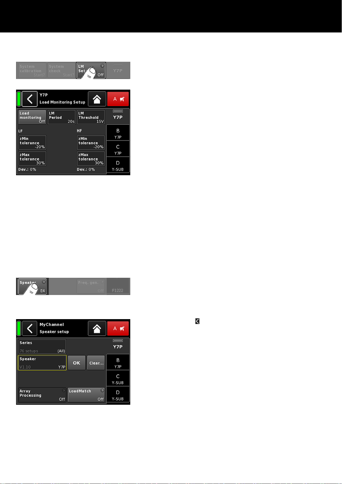
Load monitoring setup
On the «System check» screen, selecting «LM setup» opens the
corresponding subscreen.
The «Load monitoring setup» menu provides all relevant
parameters for adjustment to the on-site requirements.
Load
monitoring
On/Off
Activates Load monitoring. The On/Off status
is also indicated on the System check and
Channel setup screens.
LM Period The maximum time in detents of 20 sec. it
takes the system to detect a loudspeaker
malfunction. The intervals of the pilot signal
are derived from this parameter.
LM Threshold
Large signal threshold. When the output
signal exceeds this voltage level during the
measurement, the tolerance limits for this
particular measurement are increased in
order to compensate for the reduced
accuracy.
zMin
tolerance
zMax
tolerance
Lower limit of the impedance window, which
is set to –20 % by default.
Upper limit of the impedance window, which
is set to +30 % by default.
Dev.: Relative deviation in percent in relation to the
reference values determined during
calibration.
10.8. Speaker
Selecting «Speaker» opens the Speaker setup subscreen which
enables the selection of loudspeaker setups for the applicable d&b
loudspeakers (depending on the selected output mode).
The setups available are arranged in two blocks, «Series» and
«Speaker».
Back (
) The Back button provides two options:
1. The selection has not been confirmed by
tapping «OK» Þ Cancel:
Exits the subscreen and the previous
configuration remains active.
2. The selection has been confirmed by tapping
«OK»: Exits the subscreen.
Series The bottom left of the «Series» Input field displays
the number of setups available while the bottom
right displays the actual name of the Series.
The list is in alphabetical order, the starting point,
however, is the Series currently loaded.
Selecting «(All)» provides direct access to all
setups available and the LINEAR setup.
d&b D80 Manual 1.9 en 59
Page 60
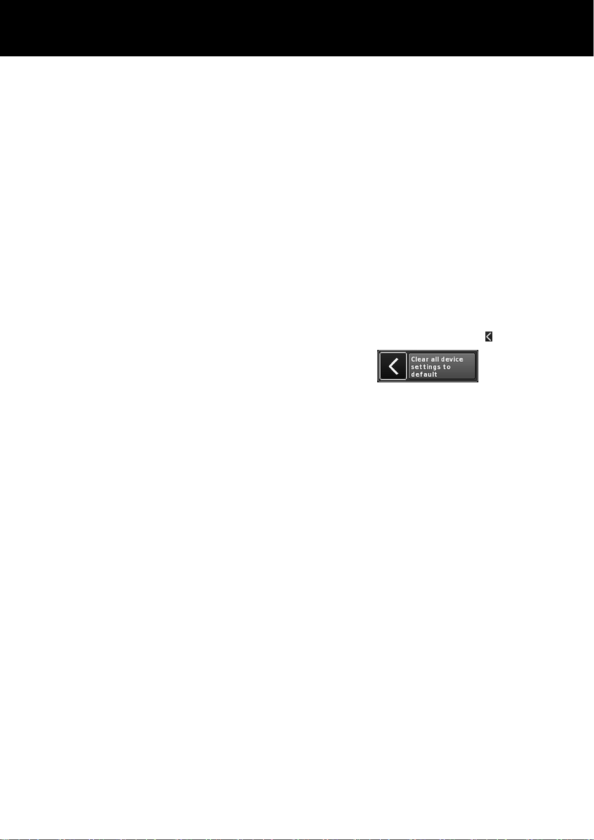
Speaker The bottom left of the «Speaker» input field
displays the version of the selected loudspeaker
setup while the bottom right displays the actual
setup name.
The loudspeaker list is either in numerical or
alphabetical order depending on the selected
series.
When «(All)» is selected in the «Series» field, the
list starts with the numeric setup names followed
by the remaining setup names in alphabetical
order. The starting point, however, is the setup
currently loaded.
OK
Selecting «OK» adjacent to the «Speaker»
selection field confirms the configuration and the
selected setup will be activated.
Clear... To prevent accidental reset when you tap the
«Clear...» button, a dialog will pop up prompting
you to confirm the reset or cancel the sequence
by tapping the Back button ( ).
Selecting the «Clear...» button clears/resets the
following loudspeaker related settings of the
respective channel.
– Configuration switches (Filter_1, Filter_2,
Filter_3) are reset.
– Level is set to 0 dB.
– Delay settings are reset (the selected unit will
be kept).
– All EQ settings are reset.
Array
Processing
For applicable loudspeakers, the
«ArrayProcessing» button becomes functional. It
indicates the On/Off status of the function and
provides direct access to the ArrayProcessing
subscreen, which is described in
Þ Chapter 10.8.1. "ArrayProcessing (AP)"
on page 61.
Note: ArrayProcessing does not apply to
all loudspeakers. When the function is not
applicable, this button is not functional.
LoadMatch For applicable loudspeakers, the «LoadMatch»
button becomes functional. It Indicates the
On/Off status of the function and provides direct
access to the LoadMatch subscreen which is
described in Þ Chapter 10.8.2. "LoadMatch"
on page 62.
Note: LoadMatch does not apply to all
loudspeakers. When the function is not
applicable, this button is not functional.
d&b D80 Manual 1.9 en60
Page 61

10.8.1. ArrayProcessing (AP)
Usually ArrayProcessing (AP) data are generated within the
ArrayCalc software and transferred to the amplifiers via the d&b
Remote network (OCA) using R1 V2.
However, once the ArrayProcessing data have been transferred to
an amplifier remotely, each data slot may also be accessed
locally.
ArrayProcess
Selection field for each memory slot.
ing slot
Note: The first slot (1) is reserved as a
bypass slot.
Below the selection field, the slot name and
version are displayed together with the
comment for the slot that was previously
entered in ArrayCalc.
In addition, the selected slot is indicated on the
respective channel strip on the «Home» screen.
Clear all slots Resets all slot data.
d&b D80 Manual 1.9 en 61
Page 62

10.8.2. LoadMatch
Selecting «LoadMatch» on the Speaker setup screen opens the
corresponding subscreen.
Þ
To activate LoadMatch, tap the On/Off button on the left next
to the «Cable length» input field.
For applicable loudspeakers, the d&b LoadMatch function enables
the amplifier to electrically compensate for the properties of the
loudspeaker cable used. This function, which covers a bandwidth
of up to 20 kHz, preserves the tonal balance when cable lengths
of up to 70 m (230 ft) are used.
LoadMatch does not require an additional sense wire and is
therefore applicable with any connector type used.
To provide optimum compensation, LoadMatch requires the entry
of the following three parameters:
Cable length
Length of the cable in meters in steps of 5 m.
Þ
The corresponding length in "ft" is
displayed on the bottom left of the input
field.
Speaker count Number of cabinets connected.
Cross-section
Cross section in square millimeters (mm2) in
steps of 0.5 mm2 up to a maximum of
10.0 mm2.
Þ
The corresponding "AWG" value is
displayed on the bottom left of the input
field.
Þ
The resulting cable impedance is shown
as an ohmic value in the
«Cable impedance» information field
underneath.
Maximum gain reached
Depending on the LoadMatch settings, the message
«Maximum gain reached» indicates the limit up to which the
LoadMatch function works.
d&b D80 Manual 1.9 en62
Page 63

10.8.3. LINEAR setup
In addition to the loudspeaker specific setups, a LINEAR setup is
also available allowing the D80 to be used as a linear power
amplifier.
Note: CUT in LINEAR setup:
– Butterworth 2nd order (12 dB/oct.)
– Corner frequency: 110 Hz
– Amplifier gain @ 0 dB: 31 dB.
10.9. Frequency generator - Freq. gen.
Selecting «Freq. gen.» opens the corresponding subscreen.
Each amplifier channel is equipped with an independent signal
generator offering sine wave or pink noise signals.
The generator provides pure-spectral sine wave signals with high
frequency accuracy and free of harmonics.
The generator can be used to check the connected loudspeakers
or to identify room resonances, for example.
The generator is inserted in the signal path after the input section
and before the actual signal processing. The test tone will sum up
with any input signal present.
Note: As a precautionary measure, the frequency generator
is always set to Off after the device is powered on.
Off
The frequency generator is switched off
(Bypass).
Sine/
Pink noise
To turn the frequency generator on, select
either «Sine» or «Pink noise», depending on
the desired signal.
Frequency The frequency is adjustable from 10 Hz to
20 kHz.
On the top right of the «Frequency/FRQ» input
field, the increment is displayed as an octave
value. When you tap the field for the first time,
the frequency increment is set to 1/6 octave.
When you tap the field again, you can toggle
between 1/6 and 1/96 octave increments.
To confirm the set frequency, press the
encoder.
d&b D80 Manual 1.9 en 63
Page 64

Level The level in dBu is adjustable from –57.5 dB
to +6 dB in 0.5 dB steps.
The level value corresponds to the level at the
controller signal input. The actual output
voltage depends on the channel input gain,
the frequency dependent gain of the selected
loudspeaker setup and the EQ settings, if
applicable.
On the Home screen, the On/Off status of the generator is
indicated by the entry «FG» on the Channel view button of the
corresponding channel strip, as shown in the graphic opposite.
d&b D80 Manual 1.9 en64
Page 65

11. Web Remote interface
In addition, a Web Remote interface is integrated which provides
direct access to the user interface of a single amplifier using a
standard web browser.
Note: The user interface of the amplifier can only be
accessed after connecting the amplifier to a computer via
Ethernet. It is possible to connect the computer and the
amplifier directly, however, this requires to manually set static
IP addresses.
For this reason, the use of a router with DHCP server is
recommended for setting up the network connection. If the
router also provides a wireless access point, the amplifier may
also be controlled using mobile devices.
Recommended and tested browser
Windows:
Firefox V 7.0 or higher
Internet Explorer: None
OSX: Safari V 5.0 or higher
Firefox V 7.0 or higher
Internet Explorer: None
iOS: iOS 6 or higher
Android: Mobile Firefox V 27.0 or higher
Remote control
To enable remote control via the Web Remote interface, proceed
as follows:
1. Establish a connection between the etherCON connector of
the amplifier and the router.
Up to three (3) amplifiers may be daisy chained to
Þ
connect to one single port of the router.
After a while, the «Remote» tab of the amplifier screen will
display the IP address the DHCP server has assigned to the
device.
2. Type this address into the address field of the browser or the
mobile device that is connected to the network.
In this case: 192.168.11.194
Þ
3. For multiple amplifiers, open one browser tab for each
amplifier connected and apply the corresponding IP address.
Web Remote interface page
The Web Remote interface page is split into three tabs: the
«Web Remote», the «Event log» and the «Commands» tabs.
Web Remote
The «Web Remote» tab shows the actual screen of the connected
amplifier.
All screens and screen items can be accessed in the same manner
as on the touch screen by simply clicking the relevant screen item.
The refresh rate can be set to fast or slow.
Refresh
Refresh rate is1 second.
fast
d&b D80 Manual 1.9 en 65
Page 66

Refresh
slow
Default setting: Refresh rate is 30 seconds.
This setting is recommended for larger amplifier
networks in order to minimize network traffic.
However, when you click any screen item, the
screen will be refreshed within 1 second.
To change the value of an input field such as CPL, Level, Delay
time, EQ settings or Speaker setup, proceed as follows:
1. Click the appropriate field and change the value using the
«Value +»/«Value –» buttons.
As an alternative, values can also be adjusted using the wheel
mouse.
Simply select the appropriate field and adjust the value
Þ
using the wheel.
2. To confirm the set value, click the relevant field again or click
the respective «OK» button.
3. To change/enter a device or channel name as well as IP
settings, click the relevant screen item.
An input mask will be displayed which allows you to enter
Þ
the desired data by clicking the respective characters
and/or numbers.
4. Confirm your entry by clicking the corresponding «OK» button.
Keyboard entries
In addition, entries such as Device name or Channel name as well
as IP addresses can also be entered using the keyboard.
However, depending on the behavior of the browser or its settings,
some characters may be not accepted or may change the focus.
Event log
The «Event log» stores a maximum of 10000 records. Once the
maximum number of records is reached, the system starts deleting
the first ones Þ Ring buffer.
The number of records displayed depends on the size of the
browser window.
Located on the right-hand side of the record list
are various Navigation buttons allowing you
to scroll through the list using the
«Page Up/Down» or «Line Up/Down» buttons
or by directly jumping to the «Latest» record.
In addition, the editable «Record» field allows
you to enter a dedicated record number. The
corresponding record will be displayed at the
very bottom of the record list.
Storage option ( )
In addition, a storage option is provided which allows you to store
the Event log data locally. This is mainly intended for service
and/or troubleshooting purposes.
To save the Event log data locally, proceed as follows:
d&b D80 Manual 1.9 en66
Page 67

1. Select the «Save» button at the bottom right corner of the web
browser window.
A corresponding dialog will pop up providing you with a
Þ
drop-down list from which you can select either the number
(«Last [n]») of records or «All» records to be saved.
2. Choose the desired option from the drop-down list and select
«Save».
The event log data will be downloaded and the download
Þ
progress will be displayed.
Once the download is completed, a corresponding
message will be displayed.
3. Select «Save» to store the Event log data locally.
Your web browser will display the corresponding dialog
Þ
and the file will be saved as Event.log to the local
download directory you have specified in the download
settings of your browser.
Commands
This functionality is intended for service purposes only
Licenses and Copyright
Selecting the d&b logo at the top left opens the
«Licenses and Copyright» information page.
d&b D80 Manual 1.9 en 67
Page 68

12. Operation (Hardware references)
12.1. Power supply
The device utilizes a switch mode power supply with active Power
Factor Correction (PFC) and automatic mains range selection.
The power supply is equipped with mains voltage monitoring,
overvoltage and undervoltage protection as well as an inrush
current limiter.
12.1.1. Active Power Factor Correction (PFC)
The active Power Factor Correction provides a clean and highly
efficient sinusoidal current draw, thus providing highest
performance under adverse mains conditions or when very long
power cabling is necessary.
The power factor is above 0.9 for mains power consumption
values of 500 W or higher.
12.1.2. Automatic mains range selection
The automatic mains range selection enables the device to be used
with any mains supply worldwide without the need for manual
action.
High range
208 - 240 V AC
Low range 100 - 127 V AC
Nominal mains ranges
Behavior with fluctuating mains voltages
With mains voltages other than the nominal voltages specified
above, the device switches to the adequate mode for either
'Protection' or 'Operation'.
The voltage thresholds are dependent on the slope of the mains
voltage change.
Undervoltage
Undefined
Overvoltage
The Main Power Supply is switched off. In
undervoltage state, the auxiliary mains
supply for device control only operates to a
limited extend.
0
Ü
75
Ü
133
Ü
170
Ü
266
Ü
Undervoltage Low range Undefined High range Overvoltage
Protection Operation Protection Operation Protection
0
Þ
85
Þ
140
Þ
190
Þ
276
Þ
12.1.3. Mains voltage monitoring
The mains voltage and frequency are recorded by the power
supply and can be viewed on screen. Where voltages outside of
this range are present, a self-resetting protective circuit responds
quickly to isolate the internal Main Power Supply leaving only a
supervisory circuit running to monitor the mains voltage. The device
accepts mains voltages of up to 400 V AC
without damage to
RMS
the device in case of a missing neutral line or running phase to
phase.
400
400
d&b D80 Manual 1.9 en68
Page 69

12.1.4. Mains inrush current limiter
The Main Power Supply is started softly to limit inrush current. Up
to two D80 may be powered up at the same time without
triggering a line circuit breaker of 13-16 A (230 V) or 30 A
(100-120 V) respectively. Inrush current is limited to:
– 13 A
– 22 A
– 27 A
@ 230 V AC
RMS
@ 120 V AC
RMS
@ 100 V AC
RMS
12.1.5. Mains supply requirements
Due to the high power capability of the amplifier, properly
dimensioned mains supply installation and distribution are
essential.
However, the mains supply benefits from the built-in active PFC
(Power Factor Correction) function of the amplifier, which causes
an almost ideal (sinusoidal) current shape. Power losses of the
mains supply and cables are kept to the lowest possible minimum.
Due to its automatic mains voltage selection, the amplifier can be
fed from all usual mains voltages within the rated ranges as stated
in Þ Chapter 12.1.2. "Automatic mains range selection"
on page 68. Within these ranges, the mains voltage does not
affect average output power figures due to the built-in regulated
power supply. However, the dynamic character of common audio
signals may cause short-time power peaks being twice as high as
the average values. The resulting higher current draw causes an
increased voltage drop on the mains line which may reduce the
available output power if it gets too high.
To ensure safe and stable operation, observe the following
recommendations and specifications:
– Operate a single amplifier on a 16 A circuit breaker at 208 to
240 V (high range) or on a 30 A circuit breaker at 100 to
127 V (low range).
– Operate the amplifier at a high-range supply (208 to 240 V),
if possible. A low-range supply (100 to 127 V) requires a
cable cross section that is 4 times higher to achieve
comparable power performance.
– When three amplifiers are operated with a three-phase
(120°) mains supply, the current on the N (neutral) conductor
can be minimized by matching loads and signals between the
three devices.
– Keep the supply line as short as possible and its cross section
as high as possible, especially when operating the device at
100 to 127 V. Voltage drop at full load (30/15 A at
115/230 V) should not exceed 5 %. For reference
specifications, refer to the following table.
d&b D80 Manual 1.9 en 69
Page 70

Maximum cable length for 5 % voltage drop at 3600 W mains power draw
Cable cross section 100 V 120 V 208 V 230 V
1.3 mm2 - AWG 16
2
1.5 mm
2.1 mm2 - AWG 14
2
2.5 mm
3.3 mm2 - AWG 12
2
4.0 mm
5.3 mm2 - AWG 10
2
6.0 mm
8.4 mm2 - AWG 8
Not permitted Not permitted 21 m/69 ft 25 m/82 ft
Not permitted Not permitted 24 m/79 ft 29 m/95 ft
Not permitted Not permitted 33 m/108 ft 40 m/131 ft
Not permitted Not permitted 40 m/131 ft 49 m/161 ft
12 m/39.5 ft 18 m/60 ft 53 m/174 ft 64 m/210 ft
15 m/50 ft 21 m/69 ft 63 m/206.5 ft 78 m/256 ft
19 m/62 ft 28 m/92 ft 83 m/272 ft 102 m/334.5 ft
22 m/72 ft 32 m/105 ft 95 m/312 ft 116 m/380.5 ft
31 m/101 ft 44 m/144 ft 133 m/436 ft 162 m/531.5 ft
12.1.6. Generator operation/UPS requirements
To operate the amplifier using a mains generator or uninterruptible
power supply (UPS), observe the following:
– With the D80 amplifier the apparent power figure (VA value)
is about the same as the effective power figure (W value).
– Use a generator or UPS that can deliver the maximum power
required by the entire system. Assume a short time power
draw of 7 kVA per D80. This is particularly important when
using a UPS without dedicated short-time overload capability.
– Run the generator or UPS at 220 to 240 V, if available. 50 or
60 Hz is not an issue.
12.2. Power amplifiers
The power amplifiers fitted to the D80 utilize Class D technology
similar to a switch mode power supply. Compared to the known
linear amplifier concept (Class A, AB, G or H), Class D power
amplifiers produce less heat and allow for a compact and lightweight design.
While supplying very high maximum output swing, it maintains high
efficiency with any kind of signal and load and runs as cool as
possible. Channels share the same power supply and are thermally
coupled to provide even higher average power figures when
unevenly loaded. TOP/SUB setups and active cardioid subwoofers
are cases of typical use. A sophisticated circuit design decreases
the impact of the load on the amplifier performance and enables a
well defined sound reproduction. A comprehensive set of
protection features individually prevents each channel from
overload and/or damage/defect. Channels that are not affected
will continue to operate, if safely possible.
d&b D80 Manual 1.9 en70
Page 71

12.3. Cooling fans
Three temperature and level controlled fans are incorporated for
cooling the internal components, which allows greater cooling
during louder program material. The fan speed is consequently
reduced during quieter passages preventing background noise
interference. If the unit heats up a «Temp. Warning» is issued and
the fans will give full cooling power permanently.
12.4. Current/power draw and thermal dissipation
Measurement references
Signal CF 12 dB: Represents 1/8th of the nominal power.
Signal CF 9 dB: Represents 1/4th of the nominal power; power
is limited to the nominal line current.
Continuous (cont.): Unlimited time. Thermal conditions may
affect power figures.
Maximum (max.): Values are measured 1 sec. after signal was
applied.
230 V AC / 50 Hz / 0.5 Ω Source impedance
Mode/Signal Load
Line
current
A
RMS
Power
factor
Input
power
W
Output
power
(sum.) W
Power
loss
W
Thermal
dissipation
BTU/hr
Thermal
dissipation
kCal/hr
OFF – 0.14 0.08 2 0 2 7 2
Standby – 0.18 0.26 10 0 10 34 9
Idling – 0.85 0.83 162 0 162 553 139
Signal CF 12 dB cont. 4 Ω/Ch. 12.50 0.98 2780 2150 630 2150 542
Signal CF 9 dB cont. 4 Ω/Ch. 18.00 0.98 4140 3136 1004 3426 863
Signal CF 9 dB max. 4 Ω/Ch. 24.00 0.98 5500 4000 1500 – –
208 V AC / 60 Hz / 0.5 Ω Source impedance
Mode/Signal Load
Line
current
A
RMS
Power
factor
Input
power
W
Output
power
(sum.) W
Power
loss
W
Thermal
dissipation
BTU/hr
Thermal
dissipation
kCal/hr
OFF – 0.13 0.08 2 0 2 7 2
Standby — 0.18 0.25 10 0 10 34 9
Idling – 0.93 0.82 160 0 160 546 138
Signal CF 12 dB cont. 4 Ω/Ch. 13.80 0.98 2822 2150 672 2293 578
Signal CF 9 dB cont. 4 Ω/Ch. 18.00 0.98 3635 2800 835 2849 718
Signal CF 9 dB max. 4 Ω/Ch. 27.00 0.98 5600 4000 1600 – –
d&b D80 Manual 1.9 en 71
Page 72
120 V AC / 60 Hz / 0.2 Ω Source impedance
Mode/Signal Load
Line
current
A
RMS
Power
factor
Input
power
W
Output
power
(sum.) W
Power
loss
W
Thermal
dissipation
BTU/hr
Thermal
dissipation
kCal/hr
OFF – 0.09 0.07 1 0 1 3 1
Standby – 0.17 0.44 9 0 9 31 8
Idling – 1.57 0.89 168 0 168 573 144
Signal CF 12 dB cont. 4 Ω/Ch. 25.50 0.98 3000 2150 850 2900 731
Signal CF 9 dB cont. 4 Ω/Ch. 30.00 0.98 3600 2600 1000 3412 860
Signal CF 9 dB max. 4 Ω/Ch. 54.00 0.99 6400 4000 2400 – –
100 V AC / 60 Hz / 0.2 Ω Source impedance
Mode/Signal Load
Line
current
A
RMS
Power
factor
Input
power
W
Output
power
(sum.) W
Power
loss
W
Thermal
dissipation
BTU/hr
Thermal
dissipation
kCal/hr
OFF – 0.08 0.07 1 0 1 2 0
Standby – 0.17 0.50 9 0 9 31 8
Idling – 1.82 0.91 163 0 163 556 140
Signal CF 12 dB cont. 4 Ω/Ch. 32.50 0.99 3250 2150 1100 3753 946
Signal CF 9 dB cont. 4 Ω/Ch. 29.00 0.99 2900 2000 900 3071 774
Signal CF 9 dB max. 4 Ω/Ch. 55.00 0.99 5500 3500 2000 – –
d&b D80 Manual 1.9 en72
Page 73

13. Service/Maintenance and care
13.1. Service
CAUTION!
Potential risk of explosion.
The device incorporates a lithium battery which may cause danger
of explosion if not replaced correctly.
– Refer replacement only to qualified service personnel
authorized by d&b audiotechnik.
– Only replace with the same type of battery.
Do not open the device. No user serviceable parts inside. In case
of any damage do not operate the device under any
circumstances.
Refer servicing only to qualified service personnel authorized by
d&b audiotechnik. In particular if:
– objects or liquids have entered the device.
– the device does not operate normally.
– the device was dropped or the housing is damaged.
13.2. Maintenance and care
During normal operation, the amplifier provides maintenance-free
service.
Due to the cooling concept, no dust filters are required. As a result,
filter exchange or cleaning is not necessary.
After a certain period of time, the touch screen may require
cleaning or calibration.
For this purpose, proceed as follows:
13.2.1. Touch screen cleaning
If the touch screen requires cleaning ...:
– use a soft cloth only.
– do not use any solvent cleaners.
For cleaning very heavy dirt on the panel, it may be helpful to use
a special cleaning spray for TFT screens. In this case proceed as
follows:
1. Spray on the soft cloth before wiping the screen.
Never apply/spray directly on the screen as the liquid
Þ
could penetrate the device.
2. Wipe the screen with moderate pressure.
d&b D80 Manual 1.9 en 73
Page 74

13.2.2. Touch screen calibration
Indication
Due to mechanical impact or the aging process of the touch
screen, its calibration references may change.
An indication is that when you tap a specific button and the
adjacent button is activated instead or when ap specific button
does no longer work.
In such cases, the touch screen should be recalibrated.
Calibration
To calibrate the Touch screen proceed as follows:
1. From the «Home screen» go to "«Device setup» Þ «More»
Þ «Preferences» Þ «Display»".
2. Select «Touch screen calibration».
The Screen calibration menu will be opened guiding you
Þ
through the calibration procedure.
3. Follow the on screen instructions respectively.
d&b D80 Manual 1.9 en74
Page 75
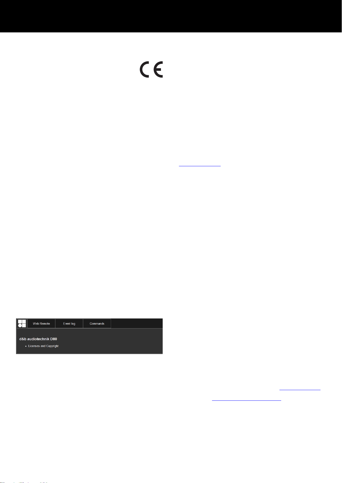
14. Manufacturer's Declarations
14.1. EU declaration of conformity (CE symbol)
This declaration applies to:
d&b D80 Amplifier, Z2710
manufactured by d&b audiotechnik GmbH.
All products of type D80 starting from variant Z2710.000 are
included, provided they correspond to the original technical
version and have not been subject to any later design or
electromechanical modifications.
We herewith declare that said products are in conformity with the
provisions of the respective EC directives including all applicable
amendments.
A detailed declaration is available on request and can be ordered
from d&b or downloaded from the d&b website at:
www.dbaudio.com.
14.2. WEEE Declaration (Disposal)
Electrical and electronic equipment must be disposed of separately
from normal waste at the end of its operational lifetime.
Please dispose of this product according to the respective national
regulations or contractual agreements. If there are any further
questions concerning the disposal of this product, please contact
d&b audiotechnik.
14.3. Licenses and Copyright
This device includes software components released under different
open source licenses. These components are supplied together with
the d&b firmware.
A list of the components and a full-text version of all licenses and
copyrights can be accessed using the amplifier's Web Remote
interface as described in Þ Chapter 11. "Web Remote interface"
on page 65.
Þ
Selecting the d&b logo at the top left of the «Web Remote»
interface page opens the «Licenses and Copyright»
information page.
This page provides an overview of the open source software used
in this product. As required by the GPL and LGPL licenses, we will
send you a copy of the used source code on request. If you would
like to obtain a copy, please contact us by mail to:
d&b audiotechnik GmbH
Eugen-Adolff-Strasse 134, D-71522 Backnang, Germany
T +49-7191-9669-0, F +49-7191-95 00 00,
info@dbaudio.com
or by email at: software.support@dbaudio.com
d&b D80 Manual 1.9 en 75
Page 76

15. Appendix
15.1. System check - References
Typical impedance (Z) values
The following table indicates typical impedance values in ohms for
d&b loudspeakers. With correct measurement conditions and
relatively short cables, measured impedances should be within a
range of ±20 % of the values indicated in the table.
The values refer to a single cabinet. When two cabinets are
connected in parallel, the total impedance is halved, with three
cabinets it will be a third and so on.
Note: Please note that the LF values were determined by the
amplifiers' measurement algorithms using sine wave signals. A
DC resistance measurement using a multimeter may produce
different results.
D80 amplifiers apply audible low level signals in the Low
frequency range for a few seconds using dedicated
frequencies for each cabinet type. This reduces the impact of
ambient temperature and mechanical aging of the driver
components on the impedance values.
System
Z LF Z HF Z MF/LF rear
16C 7.5 12 -
24C 12 11 -
24C/CE 7 11 -
10AL/10AL-D 17 13 -
10S/S-D/A/A-D 17 13 -
12S/S-D 7 11 -
12S-SUB 8 - -
18S/A-SUB 6.5 - -
27S/A-SUB 5 - -
4S 17 11 -
5S 16 11 -
8S 10 15 -
B1-SUB 4.5 - -
B2-SUB 3.5 - -
B4-SUB 5 - -
B6-SUB 6.5 - -
C3 8.5 4 -
C4-TOP 11 12 -
C4-SUB 6.5 - -
C6/690 9 15 -
C7-TOP 7 8 -
C7-SUB 6 - -
Ci-SUB -tbc- - -
Ci45/60/90 7.5 13 -
Ci80 11 16 -
d&b D80 Manual 1.9 en76
Page 77

System Z LF Z HF Z MF/LF rear
E0 12 11 -
E12/12-D 7 13 -
E12-SUB 8.5 - -
E12X-SUB 7.5 - -
E15X-SUB 7 - -
E3 16 21 -
E4 17 11 -
E5 16 12 -
E6 24 20 -
E8 13 16 -
E9 9 13 -
F1222 8.5 15 -
J8/J12 5.5 15 8
J-SUB 3 - 6
J-INFRA 2.5 - 4.5
M2 3.5 8 -
M4 7 13 -
M6 8 13 -
MAX 7 15 -
MAX2 6.5 15 -
MAX12 7.5 14 -
Q1/7/10 7 12 -
Q-SUB 6.5 - -
T10 14 16 -
T-SUB 6.5 - -
V8/12 8 18 -
V-SUB 5.8 - -
Y7P/10P 9 20 -
Y8/12 10 20 -
Y-SUB 6.5 - -
d&b D80 Manual 1.9 en 77
Page 78

15.2. Max. number of cabinets operated in parallel
The following table indicates the maximum number of cabinets
which can be operated in parallel by one amplifier channel in
order to be able to detect a failure of a loudspeaker component.
Note: The thresholds of the System check function defined by
the light blue area (–20 % ... +30 %) are also used by Load
monitoring to evaluate the system status. Therefore the values
in the table also apply to Load monitoring. If more cabinets
are operated in parallel, a correct supervision for single
component faults is not possible. This is of particular
importance for voice alarm and evacuation systems.
System Failure mode
Single cabinet
disconnected
HF section of
single cabinet
Single HF/MF
driver
LF section of
single cabinet
Single LF driver
16C 3 3 - 1 -
24C 2 2 - 1 -
24C-CE 1 1 - 1 -
10AL/10AL-D 3 3 - 3 -
10S/S-D/A/A-D 3 3 - 3 -
12S/S-D 2 2 - 2 -
12S-SUB 3 - - 3 -
18S/A-SUB 3 - - 3 -
27S/A-SUB 1 - - - 1
4S 3 2 - 3 -
5S 3 2 - 3 -
8S 3 2 - 3 -
B1-SUB 1 - - - 1
B2-SUB 1 - - - 1
B4-SUB 2 - - 2 1
B6-SUB 2 - - 2 -
C3 2 2 1 2 1
C4-TOP 3 2 - 3 -
C4-SUB 3 - - 3 -
C6/690 3 2 - 2 -
C7-TOP 3 2 - 3 -
C7-SUB 3 - - 3 -
Ci-SUB 3 - - 3 -
Ci45/60/90 3 2 - 3 -
Ci80 3 1 - 3 -
E0 3 2 - 3 -
E12/12-D 3 2 - 3 -
E12-SUB 3 - - 3 -
E12X-SUB 3 - - 3 -
d&b D80 Manual 1.9 en78
Page 79

System Failure mode
Single cabinet
disconnected
HF section of
single cabinet
Single HF/MF
driver
LF section of
single cabinet
E15X-SUB 3 - - 3 -
E3 3 2 - 3 -
E4 3 2 - 3 -
E5 3 2 - 3 -
E6 3 2 - 3 -
E8 3 2 - 3 -
E9 3 1 - 3 -
F1222 2 2 - 2 -
J8/J12 2 2 2 2 1
J-SUB 1 - - 1 1
J-INFRA 1 - - 1 1
M2 2 2 - 2 1
M4 3 3 - 3 -
M6 3 2 - 3 -
MAX 3 3 - 3 -
MAX2 3 3 - 3 -
MAX12 3 3 - 3 -
Q1/7/10 3 3 - 3 1
Q-SUB 3 - - 3 -
T10 3 2 - 3 -
T-SUB 3 - - 3 -
V8/12 2 1 1 1 1
V-SUB 2 - - 2 1
Y7P/10P 2 2 - 2 1
Y8/12 2 2 - 2 1
Y-SUB 2 - - 1 1
Single LF driver
d&b D80 Manual 1.9 en 79
Page 80

15.3. Error messages
The following table lists possible error messages appearing on the
display.
Id Error text Eventlog text Description Location Possible reasons
10 System error 8 System error 8 (%02Xh,
%d)
11 System error 128 System error 128
(%02Xh, %d)
Unexpected CPU reset DSP Software or hardware
error
Internal I2C
DSP
Any I2C device defect
communication fault
15 Unknown device type Unknown device type Unknown device type
16 Invalid device ident Invalid device ident %d Invalid hardware
configuration
17 Invalid CPLD version Invalid CPLD version %d
(minimum required %d)
18 Invalid ADDAC ident Invalid ADDAC board
ident %d
19 Invalid display ident Invalid display board
ident %d
20 Program error %u Program error %d, %d,
Invalid CPLD
identification
Invalid ADDAC
identification
Invalid DISPLAY
identification
Program error DSP Various
ADDAC, Amp., SMPS Missing or wrong
module identification
DSP Missing or wrong CPLD
identification
ADDAC Missing or wrong
ADDAC identification
DISPLAY Missing or wrong
DISPLAY identification
%d, %d
21 Invalid DSP Data Invalid DSP database
Invalid DSP data DSP Software error
(Position %d, Error %d)
25 Program error %u Program error %d: AWL
Program error DSP Various
error %d in AWL %d,
line %d
28 SMPS comm. error SMPS communication
error (status %04X)
29 SMPS firmware
mismatch
SMPS firmware V%d.
%02d.%02d not suitable
for hardware ident %d
30 SMPS temp err %d°C SMPS temperature error
SMPS communication
fault
Invalid SMPS
configuration
Temp-Off
DSP, SMPS DSP or SMPS defect,
cable defect
SMPS SMPS firmware does not
match module
identification
%+3d°C (power %uw)
31 SMPS overtemp %d°C SMPS overtemperature
SMPS overtemperature SMPS Poor cooling
%+3d°C (power %uw)
32 Mains overvoltage %dV Mains overvoltage (avg
%3dV, peak %3dV,
Mains overvoltage (External: Mains) Mains voltage is/was
too high
status %04X, err %04X)
34 Mains undervoltage
%dV
Mains undervoltage
(avg %3dV, peak %3dV,
Mains undervoltage (External: Mains) Mains voltage is/was
too low
status %04X, err %04X)
35 SMPS error POK SMPS error POK:
SMPS startup timeout
SMPS SMPS defect
timeout while waiting for
power-ok signal %ums
(PSF %4.1uV, avg
%5.1dV)
36 SMPS restart error SMPS error: too many
SMPS restart fault SMPS SMPS defect
restarts (restart count
%d)
d&b D80 Manual 1.9 en80
Page 81

Id Error text Eventlog text Description Location Possible reasons
38 SMPS overcurrent %dA SMPS Error: overcurrent
Mains overcurrent
(External: Power draw) Heavy output load
(I-peak %3dA, avg
%3dV, status %04X, err
%04X)
39 SMPS error IAC %dA SMPS error IAC (I-peak
SMPS fault SMPS SMPS defect
%3dA, avg %3dV, status
%04X, err %04X)
40 SMPS temp. sensor fault SMPS temperature
sensor fault (T1 %
SMPS temperature
sensor fault
SMPS SMPS defect
+3d;T2 %+3d;T6 %
+3d;T7 %+3d)
41 SMPS DC undervoltage SMPS DC undervoltage
error (I-peak %3dA, avg
Amplifier rail voltage not
reached
SMPS, Amp. Amp. overcurrent or
SMPS defect
%3dV, status %04X, err
%04X)
42 SMPS DC overvoltage SMPS DC overvoltage
error (I-peak %3dA, avg
Amplifier rail voltage
exceeded
SMPS SMPS defect
%3dV, status %04X, err
%04X)
43 SMPS supply error SMPS supply error 15V
SMPS 15 V supply fault
SMPS SMPS defect
(I-peak %3dA, avg
%3dV, status %04X, err
%04X)
44 SMPS error off %dV SMPS error: power
supply went
SMPS went
unexpectately off
SMPS, External: Mains Mains voltage is/was
too low or SMPS defect
unexpectately off (avg
%3dV, peak %3dV,
status %04X, err %04X)
45 Amp. comm. error Amp. communication
error (status %04X)
46 Amp. firmware is too old Amp. firmware version
%4.2d is too old,
Amp. communication
fault
Amp. firmware version is
older than required
DSP, Amp. DSP or Amp. defect
Amp. Amp. software error
required is %4.2d
50 Invalid device para Channel '%c': invalid
device parameters
Invalid device
parameters
DSP Software error or wrong
device type detected
(device ident %d)
51 Invalid DSP prog %u Channel '%c' : invalid
DSP program invalid DSP Software error
DSP program %d
52 DSP boot error Channel '%c': DSP boot
DSP boot error DSP DSP or software error
error (DSP program %d)
58 DSP comm. error Channel '%c': DSP
communication error
59 Invalid setup data Channel '%c': invalid
DSP communication fault DSP DSP defect or software
error
DSP invalid setup data DSP Software error
speaker setup (speaker
id %d, no. %d, err %d)
61 Invalid FIR filter %d Channel '%c': invalid FIR
filter %d (file version %d)
79 Amp. firmware mismatch Amp. firmware V%d.
%02d.%02d not suitable
for hardware ident %d
DSP invalid FIR data (External: FIR data file
invalid)
Amp. has wrong
Amp. Amp. firmware does not
firmware
Software error
support the Amp.
hardware
d&b D80 Manual 1.9 en 81
Page 82

Id Error text Eventlog text Description Location Possible reasons
80 Amp. ground fault Amp. ground fault (status
%04X, err %04X,
Ground fault External: Wrong speaker
connection
Error in speaker wiring,
ground connection
%5.1dV, %5.1dV)
81 Amp. supply fault Amp. supply fault 5 V
(status %04X, err %04X,
Amp. 5 V supply voltage
fault
Amp. Amp. defect
%4.1dV)
84 Amp. supply fault Amp. supply fault 12 V
(status %04X, err %04X,
Amp. 12 V supply
voltage fault
Amp. Amp. defect
%4.1dV)
85 Amp. supply fault Amp. supply fault GND
Amp. gnd voltage fault Amp. Amp. defect
(status %04X, err %04X,
%4.1dV)
86 Amp. supply fault Amp. supply fault 230V
(status %04X, err %04X,
Amplifier rail voltage
fault
Amp., SMPS Amp. overcurrent, Amp.
or SMPS defect
%4.1dV)
88
Amp. I2C fault Amp. I2C fault (status
%04X, err %04X)
90 Amp. DC fault Channel '%c': Amp. DC
fault
91 Amp. overcurrent Channel '%c': Amp.
Amp. internal
Amp. Amp. defect
communication fault
Amp. detected DC
Amp. Amp. defect
voltage output
Overcurrent on output (External: Cabling) Short circuit
output overcurrent
(power %uw)
92 Amp. temperature error Channel '%c': Amp.
Amp. temperature error
DSP Software fault on DSP
temperature error %d°C
(filter temp. %d°C,
power %uw)
93 Filter overtemp %d°C Channel '%c': Amp. filter
over temperature %d°C
Amp. over temperature
of output filters
Amp. Poor cooling
(power %uw)
94 Amp. clock fault Channel '%c': Amp.
Amp. clock fault Amp. Amp. defect
clock fault (%3dkHz,
power %uw)
95 Amp. overtemp %d°C Channel '%c': Amp.
Amp. over temperature Amp. Poor cooling
overtemperature %d°C
(power %uw)
96 Amp. temp sensor fault Amp. temperature sensor
fault (A %d°C, B %d°C,
Amp. temperature sensor
fault
Amp. Amp. defect
C %d°C, D %d°C)
99 Amp. temp warn %d°C Channel '%c': Amp.
temperature warning %d
Amp. temperature
warning
Amp. Poor cooling
°C (power %uw)
100 SMPS temp warn %d°C SMPS temperature
warning %d°C (power
SMPS temperature
warning
SMPS Poor cooling
%uw)
101 Filter temp wrn %d°C Channel '%c': Amp. filter
temperature warning %d
Amp. temperature
warning of output filters
Amp. Poor cooling
°C (power %uw)
120 CAN open error Could not open CAN
interface (error %d)
CAN interface open
error
DSP DSP defect or software
error
d&b D80 Manual 1.9 en82
Page 83

Id Error text Eventlog text Description Location Possible reasons
121 CAN error CAN error %d (remote
flags %02X, dbCan flags
%02X)
122 CAN warning CAN warning %d
(remote flags %02X,
CAN error Remote ID
CAN cabling or multiple
Remote IDs
(External: CAN cabling),
CAN warning (External: CAN cabling) CAN cabling or multiple
Remote IDs
dbCan flags %02X)
d&b D80 Manual 1.9 en 83
Page 84

D2020.EN .01, 06/2015 © d&b audiotechnik GmbH
www.dbaudio.com
 Loading...