

Page 1

D12 Amplifier
Hardware manual (4.9 EN)
Page 2

Symbols on the equipment
Please refer to the information in the operating manual.
WARNING!
Dangerous voltage!
General Information
D12 Amplifier
Hardware manual
Version 4.9 EN, 02/2014, D2012.E.04
Copyright © 2014 by audiotechnik GmbH; all rights reserved.
Keep this manual with the product or in a safe place so
that it is available for future reference.
When reselling this product, hand over this manual to the new
customer.
If you supply d&b products, please draw the attention of your
customers to this manual. Enclose the relevant manuals with the systems.
If you require additional manuals for this purpose, you can order them
from d&b.
d&b audiotechnik GmbH
Eugen-Adolff-Strasse 134, D-71522 Backnang, Germany
Telephone +49-7191-9669-0, Fax +49-7191-95 00 00
E-mail: docadmin@dbaudio.com, Internet: www.dbaudio.com
Page 3

Contents
1. Safety precautions...........................................................5
1.1. Information regarding use of the D12 amplifier..............................5
2. Introduction......................................................................6
2.1. Scope of supply.........................................................................................6
3. D12 Amplifier...................................................................7
3.1. D12 based systems...................................................................................7
3.2. D12 block diagram...................................................................................7
3.3. Digital signal processing..........................................................................8
3.4. D12 power amplifiers..............................................................................9
3.5. SenseDrive..................................................................................................9
3.6. Power supply............................................................................................10
3.6.1. Inrush current limiter..................................................................11
3.7. Fan..............................................................................................................11
3.8. Remote control........................................................................................11
4. Controls and indicators.................................................12
4.1. Controls.....................................................................................................12
4.1.1. Mains power switch [1].............................................................12
4.1.2. MUTE switch (A/B) (green LED) [2]........................................12
4.1.3. LEVEL/PUSH MENU (Digital rotary encoder) [3]...............13
4.2. Indicators...................................................................................................14
4.2.1. LC Display [4]...............................................................................14
4.2.2. ISP LED (A/B) - Input Signal Present (green) [5].................14
4.2.3. GR LED (A/B) - Gain Reduction (yellow) [6]........................14
4.2.4. OVL LED (A/B) - Overload (red) [7]:.....................................14
5. Connections....................................................................15
5.1. Mains panel..............................................................................................15
5.1.1. Mains power connection [8]....................................................15
5.1.2. Fuse protection [9 (a/b)]...........................................................15
5.1.3. REMOTE [10]...............................................................................16
5.1.4. SERVICE [11]................................................................................16
5.2. Connector panel (I/O Panel)...............................................................17
5.2.1. INPUT A/B [12] and LINK A/B [13].......................................17
5.2.2. INPUT DIGITAL AES/EBU [14a] and LINK [14b]................17
5.2.3. OUT A/B [15 (a/b/c)]................................................................17
5.2.4. D12 I/O modes...........................................................................17
5.2.4.1. Dual channel mode.....................................................18
5.2.4.2. Mix TOP/SUB mode...................................................18
5.2.4.3. 2-Way Active mode - Single input........................18
5.2.5. Loudspeaker wiring....................................................................19
5.2.5.1. Loudspeaker pin assignments and equivalents...19
6. Installation and operation............................................20
6.1. Installation.................................................................................................20
6.2. Operation.................................................................................................20
6.2.1. Power consumption and power loss......................................20
6.2.2. Operating conditions.................................................................21
6.2.3. Mains supply................................................................................22
7. Technical specifications..................................................23
7.1. Technical drawings.................................................................................25
D12 Amplifier, Hardware manual (4.9 EN) Contents - 1
Page 4

8. Manufacturer's declarations.........................................26
8.1. EU declaration of conformity (CE symbol).......................................26
8.2. WEEE Declaration (Disposal)...............................................................26
D12 Amplifier, Hardware manual (4.9 EN) Contents - 2
Page 5

1. Safety precautions
1.1. Information regarding use of the D12 amplifier
WARNING!
The following information is intended to prevent fires
and possible electric shocks:
The D12 is a protective class 1 unit. Make sure that the earth (ground)
contact is attached when the unit is in operation. A missing earth
(ground) contact may lead to dangerous voltages in the housing and
controls.
Never connect an amplifier output pin to any other input or output
connector pin or earth (ground). This might damage the unit or lead to
electric shock.
Lay all cables connected to the unit in such a way that they cannot be
crushed by vehicles or other equipment and that no one can step on
them.
Keep dust, moisture, water or other liquids well away from the unit. Do
not place any kind of object filled with liquids (e.g. drinks) on the unit.
Please ensure the mains connector is accessible at any time to
disconnect the unit in case of malfunction or danger.
Never operate the unit when it is open. Always disconnect the mains
power supply when replacing a defective fuse. Only use the type of
fuse listed in the specifications.
Only carry out work specified in this manual and always disconnect the
mains power supply. Even if the mains power supply is disconnected
electrical charge remains to several electronic components. After
15 min. the respective components will be discharged.
IMPORTANT!
All other work should be performed by trained service staff, especially
in the following cases:
- Mains power cable, socket or plug has been damaged
- Objects or liquids have entered the unit
- The unit is not operating normally
- The unit was dropped or the housing is damaged
The device complies with the electromagnetic compatibility requirements
of EN 55103 (product family standard for audio, video, audio-visual
and entertainment lighting control apparatus for professional use) for
the environments E1 (residential), E2 (business and commercial), E3
(outdoor use in urban areas) and E4 (outdoor use in rural areas).
Acoustic interference and malfunctions may occur if the unit is operated
in the immediate vicinity of high-frequency transmitters (e.g. wireless
microphones, mobile phones, etc.). Damage to the unit is unlikely, but
cannot be excluded. To meet the EMC requirements, use only shielded
cables with properly connected plugs for all input signal terminals.
D12 Amplifier, Hardware manual (4.9 EN) Safety precautions - 1/Page 5 of 28
Page 6
2. Introduction
This manual describes the facilities and functions of the hardware of the
d&b D12 amplifier.
A detailed description of the D12 Software and remote control is given
in the D12 Amplifier Software manual, which is also provided with the
D12 amplifier.
A number of publications with supplementary information on our
products are available from the Documentation section of our website
at www.dbaudio.com
online order form to request a printed version.
If the document you want is not detailed on the form, please enter the
title in the box after entering your address information.
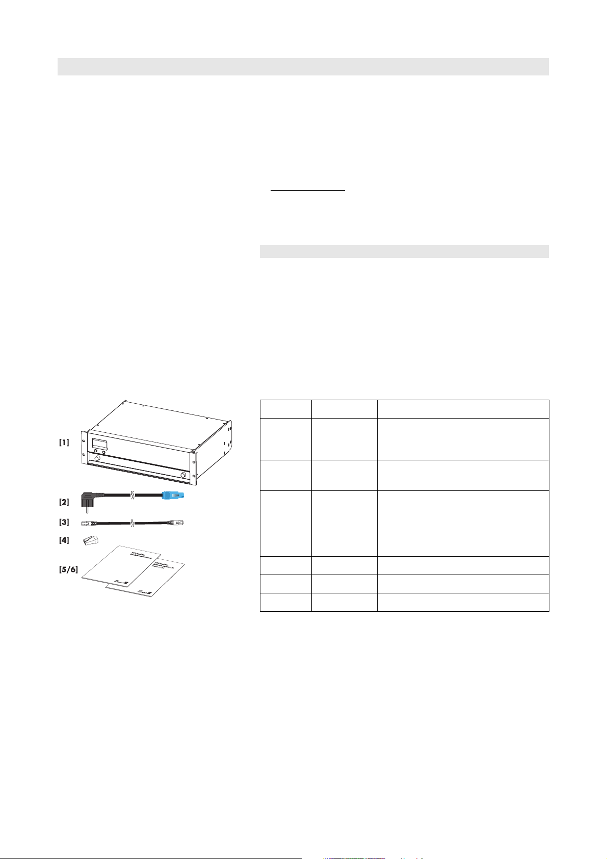
2.1. Scope of supply
Initial inspection
Before starting up the following inspections should be carried out:
- Please verify the shipment for completeness (refer to the table below
- Tab. 1).
- Please carry out a visual inspection of the packaging, the D12 unit
and the power cord for obvious damage during shipment.
. You can either download these directly or use the
Fig. 1: D12 Amplifier, scope of supply
If there is any sign of damage or incompleteness to the items listed in
the table below please contact your local dealer from whom you
received the unit.
Quantity d&b Code Description
1 Z2600 D12 Amplifier [1],
dependent on chosen output option
(EP5, NL4 or NL8 output connectors)
1 Z2610 Power cord [2]
D12 CEE (specific to country)
1 K6007.050 RJ45 Patch cable [3]
0.5 m (1.6 ft) CAT 6/AWG 24-STP
(shielded twisted pair) to be used for
daisy chaining multiple amplifiers within a
rack.
1 Z6116 RJ 45 M Terminator [4]
1 D2012.EN D12 Amplifier, Hardware manual [5]
1 D2013.EN D12 Amplifier, Software manual [6]
Tab. 1: D12 Amplifier, scope of supply
D12 Amplifier, Hardware manual (4.9 EN) Page 6 of 28
Page 7
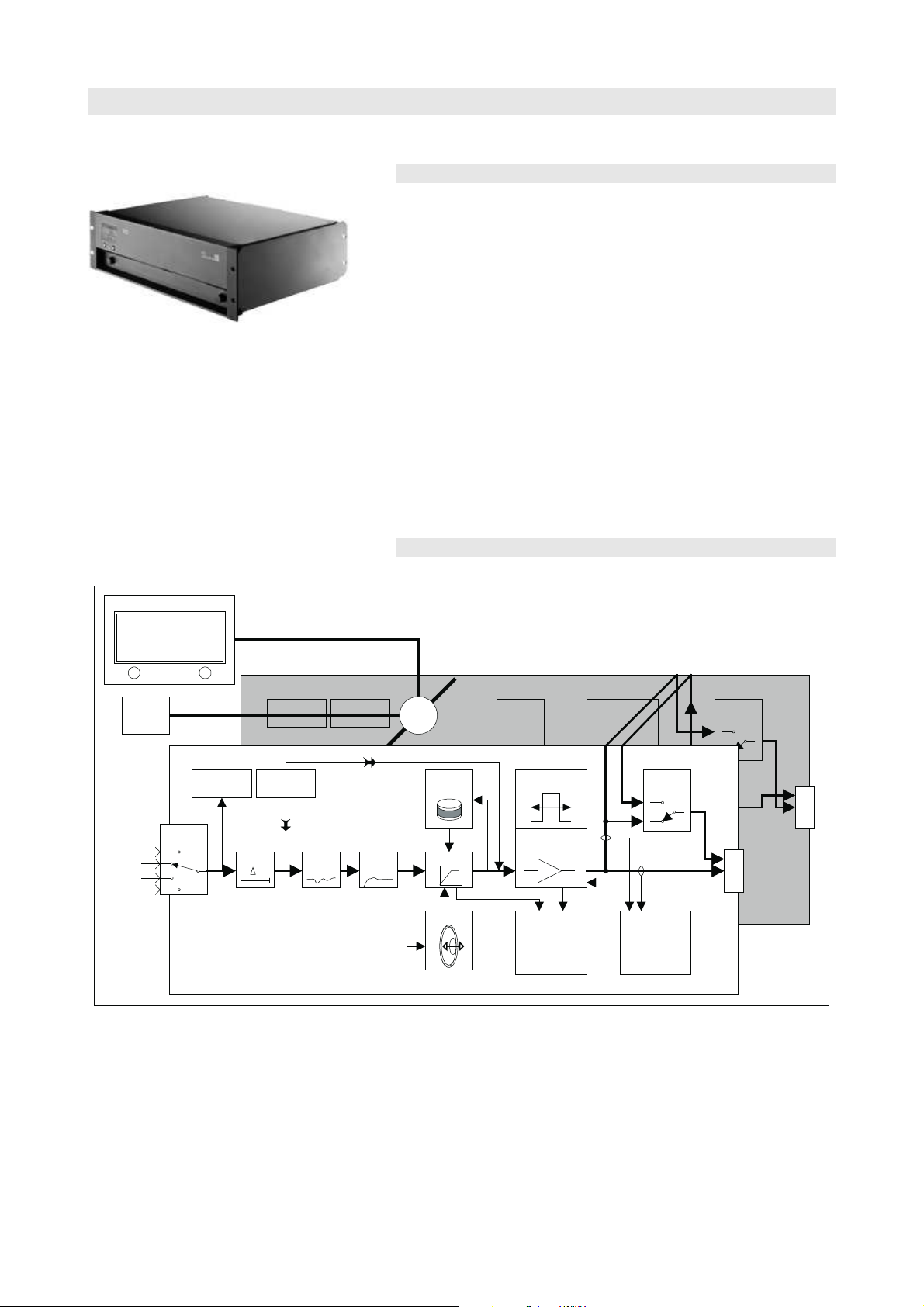
Fig. 2: D12 Amplifier
Output
routing
Power
amplifier
Input
routing
Analog A
Analog B
Digital A
Digital B
Signal
generator
sine wave or
pink noise for
acoustic tests
Input
monitoring
User
EQ
Delay
t
Dynamics
Coil temp.
t°
Power supply
Information
on headroom,
temperature,
power, mains
voltage
Excursion
1/2
3/4
5
from / to channel A
Channel B
1/2
3/4
5
System
EQ/XO
pilot signals
for load
monitoring
Channel A
LC Display
Output
Ch A
Ch B
Link A>B
Dual channel
> LINEAR
off
D12
remote
interface
Output
routing
uC
> LINEAR
Z analysis:
load
monitoring,
wiring fault
detection
1/2
3/4
5
I
3. D12 Amplifier
3.1. D12 based systems
The d&b D12 amplifier is a two channel power amplifier that
incorporates digital signal processors (DSP) providing loudspeaker
specific controller functions. It is designed for use with all current d&b
loudspeakers, and a linear mode is available.
The D12 is designed with both digital and analog signal inputs,
loudspeaker outputs, and has remote control and monitoring
capabilities.
The switch mode power supply will function with a variety of mains
voltages and allows less weight at high output power.
The level control on the front panel incorporates a digital rotary
encoder, which enables selection of all operating modes in conjunction
with a Liquid Crystal Display (LCD). The D12 includes complete signal
processing, all necessary protection circuits, REMOTE and SERVICE
interfaces, all connectors and status indicators.
The D12 is housed in a 19" x 353 mm (13.9") 3 rack unit enclosure
made from stainless steel with an extruded aluminium front panel.
3.2. D12 block diagram
Fig. 3: D12 Amplifier block diagram
D12 Amplifier, Hardware manual (4.9 EN) Page 7 of 28
Page 8

IMPORTANT!
3.3. Digital signal processing
The digital signal processing provides loudspeaker specific setups that
are selected using the front panel controls. These setups include all
loudspeaker equalization and protection functions.
A 4-band parametric equalizer is incorporated in each channel to
provide optional Boost/Cut or Notch filtering. A signal delay capability
also allows delay settings of up to 340 msec. (= 100 m/328.1 ft) to be
applied independently to either channel.
A signal generator offering pink noise or sine wave program can be
selected from the front panel controls.
Each unit can be given a unique Device Name to simplify identification
and a password protected LOCK function is also incorporated to inhibit
unauthorized setup changes.
System configurations are specific to the characteristics of each
loudspeaker and affect the frequency response and maximum output
level. To ensure optimum performance and prevent damage to system
components each type of loudspeaker has to be used in conjunction
with a suitably configured D12.
The D12 digital signal processing circuits introduce a processing delay
of 0.3 msec. into the signal path. If two identical loudspeakers are
driven by different controllers the respective delays of the units used
have to be considered (D12 = 0.3 msec., E-PAC = 1.0 msec. and
A1/P1200A no delay). The D12 effectively positions its respective
loudspeaker at a distance of 24 cm (0.79 ft) in front of a loudspeaker
driven by the E-PAC and 10 cm (0.33 ft) behind a loudspeaker driven
by the A1/P1200A.
Where the two loudspeakers form an array this will lead to an increase
in comb filtering and unpredictable coverage patterns. If the distance
between the cabinets is much greater than 1 m (3 ft) this effect becomes
negligible.
Please note that all digital signal processing equipment used in the
signal path will delay the signal. For example external digital equalizers
have a typical processing delay of about 3 ms.
D12 Amplifier, Hardware manual (4.9 EN) Page 8 of 28
Page 9

IMPORTANT!
Note:
3.4. D12 power amplifiers
The two power amplifiers fitted to the D12 can deliver 2 x 750 W
continuous sine wave power into an 8 ohms load, increasing to 2 x
1200 W continuous sine wave power into a 4 ohms load. These
maximum output ratings measured with sine wave are valid for minutes
only until the unit will switch into thermal protect.
The D12 is specifically designed to produce high power into low
impedance loads, typically those between 4 and 16 ohms. Please check
in the relevant loudspeaker manual for the recommended maximum
number of cabinets that may be driven by each channel. Due to
differences in impedance response against frequency this may vary
depending on the specific loudspeaker type.
Connecting and driving more loudspeakers will not damage the
amplifier but will limit the quality and dynamic range of reproduced
sound as the load dips below 4 ohms. Driving low impedance loads at
high levels can also trigger the amplifier protection circuits for thermal
or output current overload.
A D12 will normally be operated with speech or music program complex signals where the average power requirement is below peak
power. The D12 will continue to operate indefinitely when the Crest
Factor is higher than 2.4, provided the device is installed to enable the
heat generated to be adequately dissipated.
Please also refer to section 6.2.1. Power consumption and power loss
on page 20and section 6.2.2. Operating conditions on page 21.
Note:
3.5. SenseDrive
The accuracy of a loudspeaker’s signal reproduction, both level and
transient response, is influenced by dynamic damping factor - the ratio
of the load to source impedance.
Whilst amplifier source impedance remains constant the impedance of
the cables and connectors will largely depend upon the length and type
of cable used - longer cables produce greater signal losses depending
on the loudspeaker impedance. The impedance of a loudspeaker will
vary markedly with frequency and especially those at low frequencies.
With long cable runs this impedance variation will significantly affect the
system response.
With applicable d&b systems (EP5 and NL8 connectors only) d&b
SenseDrive compensates for the electrical properties of the loudspeaker
cable. A "sense" wire connects the signal from the LF driver back to the
amplifier where it is compared and corrected to compensate for the
cable losses. Signal reproduction is enhanced by delivering the correct
signal to the loudspeaker terminals irrespective of the cable losses.
A detailed description of the D12 SenseDrive function is given in the
technical information TI 340 (d&b code D5340.E.).
Not connecting SenseDrive for C-Series subwoofers (e.g. NL4
connectors) does not change the present performance of the system.
D12 Amplifier, Hardware manual (4.9 EN) Page 9 of 28
Page 10
3.6. Power supply
The D12 utilizes an autosensing switch mode power supply for mains
voltages 115/230 V, 50 – 60 Hz (Optional 100/200 V) and
overvoltage protection.
Where voltages outside of this range are present, a self-resetting
protective circuit responds quickly to isolate the internal amplifier power
supply leaving only a supervisory circuit to monitor the mains voltage.
The display will clearly indicate the fault and voltage value.
The supervision circuit is self-resetting.
The associated voltage ranges and/or the guaranteed (nominal)
operating ranges are listed in the following table.
Voltage range Status
0 – 98 V Undervoltage
98 – 134 V 110/115/120 V operation
134 – 195 V Undervoltage
195 – 265 V 220/230/240 V operation
265 – 400 V Overvoltage
Tab. 2: Voltage ranges 115/230 V
To prevent the D12 from cycling on and off with fluctuating mains
power supply voltages, the switching thresholds are delayed and about
4% apart from the border of the voltage range (hysteresis).
Voltage range Status
0 – 85 V Undervoltage
85 – 117 V 100 V operation
117 – 170 V Undervoltage
170 – 234 V 200 V operation
234 – 400 V Overvoltage
Tab. 3: Voltage ranges 100/200 V
D12 Amplifier, Hardware manual (4.9 EN) Page 10 of 28
Page 11

Note:
3.6.1. Inrush current limiter
A mains inrush current limiter provides a "soft start" and enables
several D12s to be powered up at the same time without overloading
the mains power supply. The maximum current drawn during the power
up phase is dependent on the mains voltage, however nominal values
are 5 A at 230 V and 10 A at 115 V and 100 V.
3.7. Fan
A level and temperature controlled fan is incorporated for cooling the
internal components, which allows greater cooling during louder
program material. The fan speed is consequently reduced during quieter
passages preventing background noise interference.
If the D12 heats up a "Temp. Warning" is given out and the fan will
give full cooling power permanently.
For further information please refer to section 6.1. Installation on page
20.
3.8. Remote control
The REMOTE sockets can be used with the dbCAN (CAN-Bus) interface
or d&b Remote Interface Bridge (RIB) to integrate the D12 into a control
and monitoring system.
A detailed description of remote control via CAN-Bus is given in the
technical information TI 312 (d&b code D5312.E.).
D12 Amplifier, Hardware manual (4.9 EN) Page 11 of 28
Page 12
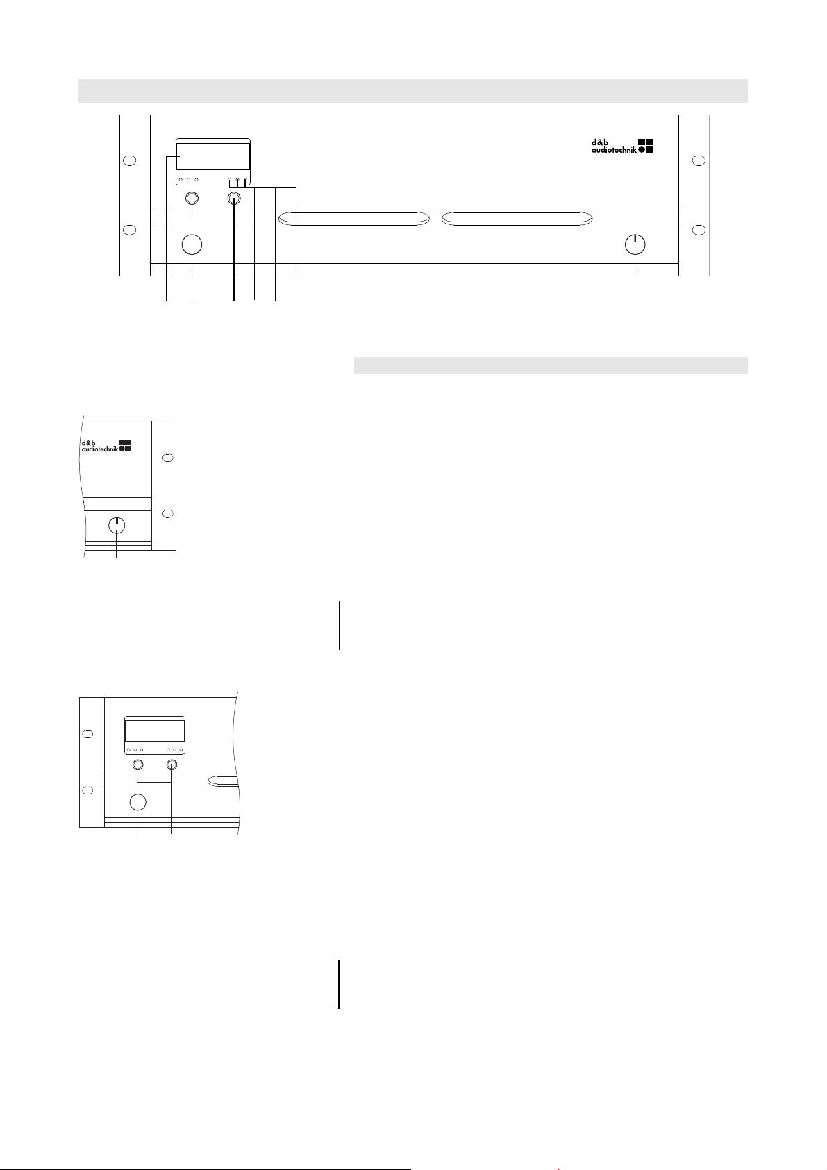
D12
LEVEL
PUSH MENU
MUTE
POWER
A
B
ON
OFF
OVLGRISPOVLGRISP
[1][3] [2][4] [5][6][7]
Fig. 4: D12 Controls and indicators
POWER
ON
OFF
[1]
D12
LEVEL
PUSH MENU
MUTEA
B
OVLGR
ISPOVLGRISP
[3] [2]
4. Controls and indicators
4.1. Controls
4.1.1. Mains power switch [1]
The on/off rotary switch is located on the right hand side at the bottom
of the front panel.
- OFF: the D12 is isolated from the mains power supply except the
overvoltage protection circuit. The power consumption is very low (2
W typical).
- ON: the D12 is switched on. Via remote or the MUTE A or B switch
the D12 can be switched to standby mode. To indicate standby mode
the display remains active.
Fig. 5: D12 Mains power switch
Note:
The mains power rotary switch is a "Brake-before-make contacts" type.
Due to this characteristic the D12 will immediately be switched off by
leaving the "ON" position.
4.1.2. MUTE switch (A/B) (green LED) [2]
When the mains power switch is set to the on position, the MUTE switch
can be used to mute the respective amplifier channel or place the D12
in standby mode using the MUTE A or B switch. The switch incorporates
a green LED indicator which indicates three different states - ON
(unmute)/MUTE and STANDBY.
- LED on: ON (unmuted): the D12 is ready for use. A brief press
of the MUTE (A or B) switch will mute the corresponding channel A or
B. A longer press (approx. 1 sec.) of MUTE A or B places the D12 in
standby mode.
Fig. 6: D12 Controls
- LED regular flashing (1:1 duty cycle): ⇒⇒⇒⇒ MUTE:
the corresponding channel of the D12 is muted however the power
amplifier remains powered but receives no signal from the controller.
A connected loudspeaker is therefore still damped.
The channel is unmuted by briefly pressing the corresponding MUTE
switch.
Note:
The setting of the MUTE A/B switch is stored in the D12 when the mains
power is turned off or disconnected. After switching on or reconnecting
D12 Amplifier, Hardware manual (4.9 EN) Page 12 of 28
the D12 it will revert to its pre-disconnection status.
Page 13

Note:
- Regular short flashes (1:8 duty cycle): ⇒⇒⇒⇒ STANDBY:
in standby mode the loudspeaker outputs are electronically isolated
and the D12 idles, drawing minimal mains power. Only the most
essential functions are provided. Display and network remain
functional, the display illumination is switched off after 10 seconds.
Pressing the MUTE A or B switch powers on the D12 ready for use.
The D12 may also be powered back on by remote control from
standby mode.
When the D12 is set to STANDBY (or the mains power is turned off) the
movement of the loudspeaker cones in the cabinets connected is no
longer damped by the power amplifier output. This removal of the
damping makes them susceptible to excitation by other loudspeakers in
the surroundings. Audible resonances may occur, and even absorption
of low frequency sound energy as the undamped loudspeakers act like
a "bass trap". To permanently mute single subwoofer cabinets when
others are operated at the same time it is therefore preferable to use
the MUTE function instead of STANDBY. The STANDBY mode, however,
can be of advantage with mid/high systems, because it will remove any
residual noise from the system.
4.1.3. LEVEL/PUSH MENU (Digital rotary encoder) [3]
Operation, configuration and status viewing of the D12 are all accessed
via the front panel digital rotary encoder - LEVEL/PUSH MENU. In the
main menu the encoder acts as a level control. Pushing or turning the
encoder gives access to different menu levels or enables configurations
or values to be entered.
Note:
- Brief press: alternating between level control of channel A or B.
- Long press (approx. 1 sec.): access to the menu level.
A detailed description of the D12 menu structure and access is given in
the D12 Software manual, which is also provided with the D12.
D12 Amplifier, Hardware manual (4.9 EN) Page 13 of 28
Page 14

OVLGRISPOVLGRISP
[4] [5][6][7][5][6][7]
CH A CH B
Fig. 7: D12 Indicators in detail
4.2. Indicators
4.2.1. LC Display [4]
Serves as a user interface and display for all configuration settings and
status information.
The display is illuminated and can be set to "on/off/timeout 10 s."
A detailed description of the menu structure and access is given in the
D12 Software manual, which is also provided with the D12.
4.2.2. ISP LED (A/B) - Input Signal Present (green) [5]
- Input - analog
Illuminates when the D12 input signal exceeds
–30 dBu: the ISP indication is unaffected by the setting of the level
control and the MUTE function but will not operate in STANDBY
mode.
- Input - digital (AES/EBU)
Illuminates when the D12 digital input is locked to 48
or 96 kHz and the signal exceeds –57 dBFS
(FS = Full Scale): the ISP indication is unaffected by the setting of the
level control and the MUTE function but will not operate in STANDBY
mode.
IMPORTANT!
Notes on the digital AES/EBU input ⇒⇒⇒⇒ Sampling rates
The two sampling rates 48/96 kHz are supported by the digital
AES/EBU input of the D12.
Other (standard) sampling rates (e.g. 32/44.1 or 88.2 kHz) will be
detected but not supported.
Non standard sampling rates will be ignored.
4.2.3. GR LED (A/B) - Gain Reduction (yellow) [6]
- Illuminates depending on the input signal: the D12 limiter
circuit reduces gain by more than 3 dB.
This state is not critical but shows that the system has reached its
limits.
4.2.4. OVL LED (A/B) - Overload (red) [7]:
- Illuminates depending on the input signal ⇒⇒⇒⇒ Overload:
either the input signal level is too high, gain reduction exceeds 12 dB
or the D12 is trying to deliver too high an output current. If in doubt
reduce the input gain at the D12 level control. If the error message
disappears, the output current has been too high (load impedance
too low caused by too many loudspeakers connected to the D12
output, or a defective cable or connector). If the condition does not
change, the input signal to the D12 is too high (greater than
+25 dBu).
An overload could also be caused by accumulating the source input
A+B or by high gain settings (boosts) in the single EQ bands, while
the input signal is lower than +25 dBu.
D12 Amplifier, Hardware manual (4.9 EN) Page 14 of 28
- Flashes (1:1 mark space) ⇒⇒⇒⇒ Error: an error message will be
displayed altering with the device name.
Page 15

OUT A
OUT B
INPUTLINK
CH B
ANALOG
DIGITAL
AES/EBU
CH A
ANALOG
SERVICEREMOTE
VOLTAGE SEE LABEL
~ 50/60 Hz
1400 W
CAUT ION
RISK OF ELE CTRI C SH OCK
DO NOT OPEN
www.dbaudio.com
MAINS SUPPLY
RISK OF FIRE - REPLA CE FUSE AS M ARKED
T10A H / 250 V
FUSE
T10A H / 250 V
FUSE
Made in Germany
[14 a][9b] [8][9a] [12][13][15(a/b/c)][10] [11]
Mains panel
I/O panel
[14 b]
Fig. 8: D12 Connections
SERVICEREMOTE
VOLTAGE SEE LABEL
~ 50/60 Hz
1400 W
CAUT ION
RISK OF ELEC TRIC SHO CK
DO NOT OPEN
www.dbaudio.com
MAINS SUPPLY
RISK OF FIRE - REPLACE F USE AS MARKE D
T10A H / 250 V
FUSE
T10A H / 250 V
FUSE
Made in Germany
[9b] [8][9a] [10 ] [11]
5. Connections
5.1. Mains panel
A PowerCon mains connector [8] is fitted on the rear panel and an
appropriate mains lead is supplied.
Two RJ45 [10] connectors are also provided for the D12 REMOTE
functions.
A D-SUB-9 SERVICE connector [11] is fitted which allows operating
software and loudspeaker configuration updates to be loaded into the
unit.
Fig. 9: D12 Mains panel
5.1.1. Mains power connection [8]
WARNING!
Only connect the D12 to mains power supplies with a
ground conductor (protective earth).
Make absolutely sure that earth is connected correctly.
IMPORTANT!
Before connecting the device to mains voltage, check that the mains
voltage and frequency corresponds to the specifications on the
configuration sticker on the rear of the D12.
5.1.2. Fuse protection [9 (a/b)]
WARNING!
If a fuse has failed disconnect the D12 from the mains
power supply before replacement.
Only use a fuse of the correct type – 5 x 20 mm/high
breaking capacity - and nominal current value. The
current value can be read from the rear mains panel
next to the respective fuse.
The mains fuses are located above the PowerCon socket and fulfill a
purely protective function in case of a device fault. They do not serve as
an overload protection.
In 200/230 V operation the upper fuse works only [9a]. In 100/115 V
operation both fuses are working [9a and b].
D12 Amplifier, Hardware manual (4.9 EN) Page 15 of 28
Page 16

1.. .... 8 1. ..... 8 Pin 1 n.c.
Pin 2 n.c.
Pin 3 n.c.
Pin 4 CAN_H
Pin 5 CAN_L
Pin 6 n.c.
Pin 7 RIB Data +
Pin 8 RIB Data Shield CAN Ground
1
8
......
Fig. 10: Pin assignment for remote control
(RJ 45)
5.1.3. REMOTE [10]
The D12 is fitted with a 2-wire serial remote control interface, (2 x
RJ 45) carrying both the RIB and CAN-Bus signals. All pins of both
connectors are wired in parallel allowing either to be used as the input
or output. Where remote control networking conforms to a "Bus or Ring
topology" one connector is used for the incoming signal and the second
connector allows for direct connection to another device (daisy
chaining) or for terminating in the case of a CAN-Bus network. The
interface connections for the RIB (pin 7/8) are opto-coupled, while the
connections for the CAN-Bus (pin 4/5) are hard wired to common
ground (protective earth).
Pin Signal Remark
1 -
2 -
3 -
4 CAN_H CAN high bus line (active high)
5 CAN_L CAN low bus line (active low)
6 -
7 RIB Data +
8 RIB Data –
Shield GND CAN Ground
IMPORTANT!
Fig. 11: SERVICE connector (D-SUB-9)
IMPORTANT!
Note:
Tab. 4: RJ45 pin assignment on d&b devices
Regarding the CAN-Bus network shielded cables and shielded RJ45
connectors must be used while the cable shielding must be connected to
both sides of the RJ45 connector as the "CAN Ground" is routed via
the cable shielding.
A detailed description of remote control via dbCAN (CAN-Bus) is given
in the technical information TI 312 (d&b code D5312.E.).
5.1.4. SERVICE [11]
The D-SUB-9 SERVICE interface (RS 232 female) allows operating
software and loudspeaker configuration updates to be loaded into the
unit.
To connect the computer to the SERVICE connector a standard RS-232
connection cable (D-SUB-9 serial cable female/male - 1:1) must be
used (serial extension cable).
Pin Signal Remark
2 RxD
3 TxD
4 DTR
5 GND Signal ground
7 RTS
D12 Amplifier, Hardware manual (4.9 EN) Page 16 of 28
Tab. 5: D-SUB-9 pin assignment on d&b devices
Page 17

OUT A
OUT B
INPUTLINK
CH B
ANALOG
DIGITAL
AES/EBU
CH A
ANALOG
Fig. 12: D12 I/O Panel
Digital INPUT
(AES/EBU)
Digital LINK
Power fail (Bypass)
Buffer
OUT A
OUT B
[15 a]
OUT A
OUT B
[15 b]
OUT A
OUT B
[15 c]
Fig. 13: Pin assignment D12 ANALOG
INPUT/LINK
Fig. 14: Pin assignment D12 DIGITAL
INPUT/LINK
5.2. Connector panel (I/O Panel)
All signal input and output connections are located on the rear I/O
panel.
These include analog and digital (AES/EBU) signal inputs and link
outputs for each channel. Loudspeaker outputs are optionally either
EP5, NL4 or NL8, dependent on the loudspeaker input version or type.
5.2.1. INPUT A/B [12] and LINK A/B [13]
A 3 pin female XLR input connector is provided for channel A and B.
Wired in parallel is a 3 pin male XLR input link connector used to feed
the input signal on to the next device in the system signal chain.
5.2.2. INPUT DIGITAL AES/EBU [14a] and LINK [14b]
A 3 pin female XLR AES/EBU (AES 3) input [14a] and a 3 pin male XLR
LINK output [14b] are provided.
The balanced input utilizes a transformer and is electrically isolated.
The digital LINK output may be used to feed a refreshed input signal to
the next device in the system signal chain. The signal shape (the rising
and trailing edges of the signal) and level are refreshed with an analog
signal amplifier.
Fig. 15: D12 Digital INPUT and LINK
Fig. 16: D12 EP5 [15a], NL4 [15b]
or NL8 [15c] output connectors
A power fail relay is incorporated to prevent interruption of the signal
chain should there be a power failure. In this situation, the digital input
signal bypasses the analog buffer amplifier and is routed directly to the
LINK output.
5.2.3. OUT A/B [15 (a/b/c)]
The D12 amplifier is supplied with EP5, NL4 or NL8 output connectors
as an option.
The pin assignment for the loudspeaker output connectors is
automatically switched depending on the I/O mode selected.
5.2.4. D12 I/O modes
There are three different output modes:
1. Dual channel mode
2. Mix TOP/SUB mode
3. 2-Way Active mode
Note:
For further information regarding the applicable output
modes for each loudspeaker system, please refer to the
respective loudspeaker manual.
Ensure that the connected loudspeaker type corresponds to
the actual configuration of the D12.
D12 Amplifier, Hardware manual (4.9 EN) Page 17 of 28
Page 18

OUT A
SenseDrive
when SUB
selected
OUT B
SenseDrive
when SUB
selected
AMP B
AMP A
INPUT A
INPUT B
Fig. 17: D12 Input/Output routing
OUT A
TOP / SUB
OUT B
TOP / SUB
SenseDrive
AMP B
AMP A
INPUT A
INPUT B
TOP
SUB
INPUT A
OUT A
2-Way
SenseDrive
OUT B
2-Way
AMP B
AMP A
Dual channel mode
with standard input routing
5.2.4.1. Dual channel mode
In "Dual channel mode" the D12 acts as a two channel amplifier –
stereo amplifier. The amplifier channels are connected to their
respective output connectors (AMP Ch A to OUT A and AMP Ch B to
OUT B). Each output connector is wired in parallel using the respective
pins for TOP or SUB configurations (refer to section 5.2.5.1.
Loudspeaker pin assignments and equivalents on page 19).
The "Dual channel mode" is dedicated to d&b fullrange systems (passive
systems) and actively driven d&b subwoofers. Both channels can be
configured for TOP or SUB cabinets independently.
In "Dual channel mode" the SenseDrive function is available for
applicable cabinets on channel A and B (with EP5 or NL8 connectors
only).
In "Dual channel mode" all four pins (TOP and SUB) are driven. This
could cause damage to TOPs when a SUB configuration is selected on
the respective channel.
The D12 will monitor the current through the different output pins and
will detect if a wrong cabinet type is connected. Depending on the
setting of the D12 the error message "Top/Sub-Mismatch" will be
given out on the LCD and the respective channel will be muted. Please
refer to the D12 Software manual section under "D12 Settings menu –
Options – TSM Detection (Top/Sub-Mismatch)".
Fig. 18: D12 Input/Output routing
Mix TOP/SUB mode
with standard input routing
Fig. 19: D12 Input/Output routing
2-Way Active mode
with standard input routing
5.2.4.2. Mix TOP/SUB mode
In "Mix TOP/SUB mode" Both amplifier channels are connected to both
output connectors (AMP Ch A and Ch B to OUT A and B). The output
connectors are wired in parallel using the respective pins for TOP and
SUB configurations. (refer to section 5.2.5.1. Loudspeaker pin
assignments and equivalents on page 19)
The "Mix TOP/SUB mode" is dedicated to d&b fullrange systems
(passive systems) and actively driven d&b subwoofers while TOP
cabinets (setups) are selectable on channel A and SUB cabinets (setups)
on channel B.
In "Mix TOP/SUB mode" the SenseDrive function is available for
applicable cabinets on channel B (with EP5 or NL8 connectors only).
5.2.4.3. 2-Way Active mode - Single input
The "2-Way Active mode" is dedicated to d&b active systems.
In "2-Way Active mode" both amplifier channels are connected to both
output connectors (AMP Ch A and B to OUT A and B) while the
loudspeaker cabinets (setups) are selectable on Channel A. All settings
of channel A and the input signal are linked to channel B and cannot be
configured individually.
In "2-Way Active mode" the SenseDrive function is available for
applicable cabinets on Channel A (with EP5 or NL8 connectors only).
D12 Amplifier, Hardware manual (4.9 EN) Page 18 of 28
Page 19

5.2.5. Loudspeaker wiring
1
2
3
4
5
LF+
LF–
HF+
HF–
EP5
SnsDrv LF
1
2
3
4
5
LF+ Front
LF– Front
LF+ Rear
LF– Rear
EP5
SnsDrv Front
NL8
LF+ Front
LF– Front
1+
1–
2+
2–
3+
3–
4+
4–
LF+ Rear
LF– Rear
SnsDrv Front
n.c.
n.c.
n.c.
LF+
LF–
MF/HF+
MF/HF–
EP5
SnsDrv
1
2
3
4
5
NL8
LF+
LF–
1+
1–
2+
2–
3+
3–
4+
4–
MF/HF+
MF/HF–
SnsDrv LF
n.c.
n.c.
n.c.
NL8
LF+
LF–
1+
1–
2+
2–
3+
3–
4+
4–
HF+
HF–
SnsDrv LF
n.c.
n.c.
n.c.
The passive full range/TOP systems and passive subwoofers use pins 1
and 2 of the EP5 connector (1+ and 1– of the NL4 connector).
Actively driven subwoofers use pins 3/4 and pin 5 of the EP5
connectors (2+ and 2– of the NL4 connector).
These pin assignments allow full range cabinets and subwoofers to be
linked together and connected to the amplifier in mixed configuration
(Mix-TOP/SUB) using a single 4 or 5-wire cable. SenseDrive is only
available when using EP5 connectors and 5-wire cables.
Pin equivalents of EP5, NL4 and NL8 connector in relation to the output
modes of the D12 amplifier are listed in the table below.
2-Way Active SUB 2-Way Active TOP Mix TOP/SUB EP5 NL4 NL8
LF+ Front LF+ TOP+ 1 1+ 1+
LF– Front LF– TOP– 2 1– 1–
LF+ Rear MF/HF+ SUB+ 3 2+ 4+
LF– Rear MF/HF– SUB– 4 2– 4–
SenseDrive LF Front SenseDrive LF SenseDrive SUB 5 n.a. 3–
Tab. 6: Pin assignments of EP5/NL4/NL8 connectors in relation to D12 output modes
5.2.5.1. Loudspeaker pin assignments and equivalents
T/Ti/Q/Qi/C/Ci/E-TOPs T/Ti/Q/Qi/C/Ci/E/B-SUBs C3/Ci3/MAX/M4
M2/F1222 J8/J12 J-SUB/J-INFRA
Tab. 7: Loudspeaker pin assignments and equivalents
D12 Amplifier, Hardware manual (4.9 EN) Page 19 of 28
Page 20
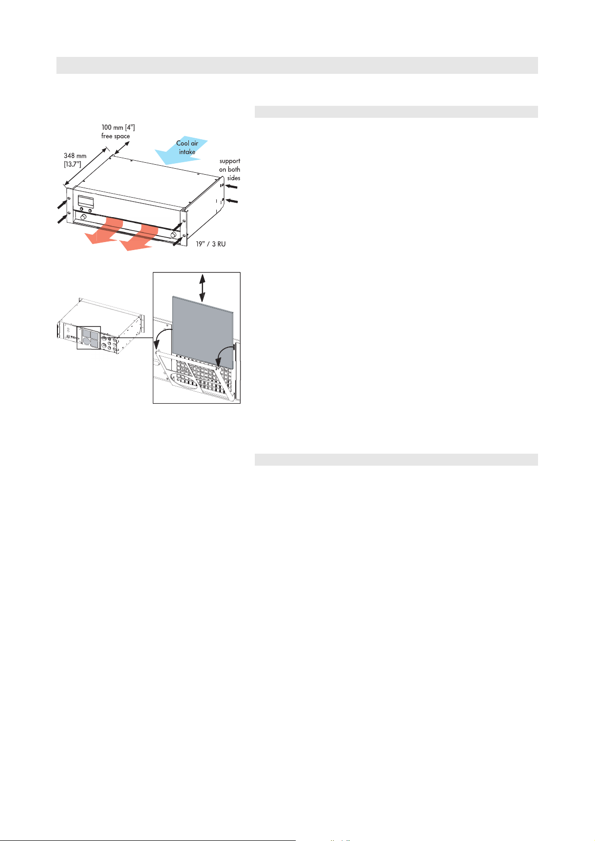
Fig. 20: D12 Installation
Fig. 21: D12 Fan filter exchange
6. Installation and operation
6.1. Installation
D12 amplifier enclosures are designed to fit a standard 19" equipment
rack or cabinet.
When specifying a rack, be sure to allow extra depth (10 cm / 4" is
usually sufficient) to accommodate the cables and connectors at the rear
of the amplifier(s).
When mounting amplifiers into a 19" rack cabinet, provide additional
support using shelves fixed to the inner sides of the cabinet or the
mounting holes provided on the amplifier rear mounted rack ears - do
not just rely on fixing and supporting amplifiers by their front panels.
This advice is particularly important if amplifiers are being racked up for
touring use.
Since the D12 amplifier can generate a lot of heat, please ensure,
whatever the mounting or racking arrangement, that adequate cool
airflow is provided to avoid a build-up of hot air inside the rack leading
to overheating. When setting up the amplifier, do not block or cover the
rear panel air intake or the vents on the front panel of the amplifier –
see Fig. 20.
We advise frequent cleaning of the fan filter to ensure good airflow
through the unit. If the filter is visibly dirty, then it should be cleaned or
replaced – see Fig. 21. Never operate the D12 without a filter. Dust
deposits, especially combined with damp conditions, could cause the
amplifier to malfunction. If amplifiers are installed in cabinets so that
direct access to the rear panel filters is not possible, we recommend
using additional fan modules with front mounted filters that can be
easily replaced without opening the sealed cabinets.
6.2. Operation
6.2.1. Power consumption and power loss
The power required from the mains supply and the waste heat
produced by the amplifiers power loss vary depending on the load
impedance and the signal levels and characteristics (e.g. speech, music).
In practice, the theoretical peak power consumption of a system will
only be sustained for a short period of time. Basing mains current and
air conditioning plant requirements on the peak power consumption of
the sound system would result in a generously over-specified
installation. The key factor in power consumption calculations is the crest
factor (CF) of the music or speech signal - the ratio of peak to
sustainable RMS voltage of the signal.
A crest factor of 2.4 represents 1/3 of the maximum sine output power
and it can be seen as the worst case signal that can be accessed in real
world conditions. A proper power distribution should be able to handle
the current ratings given in the table below (Tab. 8) referring to CF 2.4.
Using the D12 temporarily with well known signals of higher crest
factor, the power distribution can be downsized within the range given
in the table.
D12 Amplifier, Hardware manual (4.9 EN) Page 20 of 28
Page 21

Signal
0 5 10 15 20 2 5 30 3 5 4 0 4 5
0
100
200
300
400
500
600
700
800
900
Ambient Temp. in °C
Max. average output Power [W]
waveform CF Duty P
Highly
2.4 1 : 3.3 800 1230 430 9.2 18.4 20.2 1467 370
compressed
music*
Music with low
3.5 1 : 7 400 640 240 5.3 10.6 11.2 819 206
dynamic range
Music with
5.0 1 : 14 200 360 160 3.2 6.4 7.0 546 138
wide dynamic
range
Tab. 8: D12 Power balance
Key:
CF: Crest factor, Duty: Duty cycle, P
P
: Power loss (thermal power), I
loss
* Maximum practical operation
[W]: Max. average output power (sum of both channels), Pin[W]: Input power (effective power)
out
in (xxxV)
[W] Pin [W] P
out
[A]: Resulting current,
The table gives power figures for various types of signal waveforms.
They were measured on a D12 driving a 4 ohm load (both channels) to
the clipping point of both channels using a sine wave burst signal of
24 dBu with a variable duty cycle. The mains power supply used for the
measurements supplied an ideal sine wave with 230 V/50 – 60 Hz at
an internal resistance of 0.5 ohms (0.12/0.1 ohms for 115/100 V)
equivalent to a mains lead of 20 m (65.6 ft) with a cross section of
1.5 mm2 (6 mm2 / 8 mm2 for 115/100 V).
[W] I
loss
in(230V)
[A] I
in(115V)
[A] I
[A] BTU/hr kCal/hr
in(100V)
D12 Amplifier, Hardware manual (4.9 EN) Page 21 of 28
6.2.2. Operating conditions
The following diagram shows the thermal operating range within which
the technical data will be maintained. The operation beyond this range
is possible for a short time and for thermal reasons this will trigger the
amplifier protection circuit into thermal overload.
Fig. 22: Average maximum total output power vs. ambient
temperature
As explained in section 6.2.1, a worst case signal with a CF of 2.4 is
producing 1/3 of the rated sine output power or 400 watts at 4 ohms
per channel (800 watts total). The thermal management of the D12 is
designed to deliver this power for an unlimited amount of time within an
ambient temperature of up to 35 °C (95 °F). With higher ambient
temperatures, the maximum average output power that can be
delivered without entering thermal protection, is reducing linearly as
shown in the diagram.
Page 22

When using the D12 at its upper temperature limit of 45 °C (113 °F),
the maximum continuous output power is 500 watts total or 250 watts
per channel. Again referring to section 6.2.1 - (Tab. 8) - the unit will
work properly with e.g. 400 watts total when either running 4 ohms
loads when the signal has a CF of 3.5 or running 8 ohms loads if the
worst case signal with a CF of 2.4 needs to be handled.
The maximum possible output power of 2 x 1200 W at 4 ohms, which
for thermal reason could only supplied in a short term (within minutes), is
unaffected by the ambient temperature.
6.2.3. Mains supply
Number of devices per phase conductor when full output power is
required.
Mains supply Number of devices
230 V / 16 A Max. 2
115/100 V / 15 A Max. 1
Tab. 9: Mains supply and number of devices
In the USA and Japan we recommend the operation over two phase
conductors (phase to phase – 240/200 V) or the use of mains leads
with a much higher cross section (min. 4 mm2 / AWG 12).
D12 Amplifier, Hardware manual (4.9 EN) Page 22 of 28
Page 23

7. Technical specifications
Displays
ISP A/B..................................................................Input Signal Present indicator (green)
GR A/B.........................................................................Gain Reduction indicator (yellow)
OVL A/B...........................................................................Overload/Error indicator (red)
MUTE A/B......................................................................Mute/Standby indicator (green)
Liquid Crystal Display (LCD).....................................Graphic display / 120 x 32 Pixel
Controls
POWER...................................................................................................Main power switch
MUTE A/B.........................................................................................Mute/Standby switch
LEVEL/PUSH MENU..........Digital rotary encoder; access to all functions (Channel
A/B) including:
Level control.........................................................................................– 57.5 dB ... +6 dB
Filter configurations................................................................................................................
..........................Up to three loudspeaker specific filter circuits (e.g. CUT/HFA/HFC)
Equalizer...............................................Optional 4-band parametric equalizer/Notch
Delay setting...............................................................................................0.3 - 340 msec.
System setups...........................All current d&b loudspeakers/linear (MAX/MAX12)
Channel coupling..................common access to Delay, Equalizer, Delay+Equalizer
Protection..................................................Operator input inhibit/password protection
Remote control...................................................................................................dbCAN/RIB
Device name..................................................................................15 alphanumeric digits
Display illumination....................................................................Off/On/Timeout 10 sec.
Frequency generator....................................Pink Noise or Sine wave, 1 Hz - 20 kHz
.....................................................................................................Level: – 57.5 dB ... +6 dB
Buzzer..........................................................................Audible signal for error messages
Connectors
INPUT ANALOG CH A / CH B............................................................3 pin XLR female
pin assignment: 1 = GND, 2 = pos. Signal, 3 = neg. Signal
Input impedance.......................................................44 kOhm, electronically balanced
Common mode rejection (CMRR, 20 Hz – 20 kHz)........................................> 63 dB
Maximum input level..............................................................................................+25 dBu
.................................................................................................................+27 dBu @ 0 dBFS
LINK ANALOG CH A / CH B..................................................................3 pin XLR male
pin assignment: 1 = GND, 2 = pos. Signal, 3 = neg. Signal
INPUT DIGITAL AES/EBU.........................................................3 pin XLR female, AES 3
pin assignment: 1 = GND, 2 = Signal, 3 = Signal
Input impedance.........................................................110 ohms, transformer balanced
Sampling..................................................................................48 kHz / 96 kHz / 2 Ch/n
Synchronization.................................Word-Sync: PLL-locked to source (slave mode)
LINK DIGITAL (Output)..............................................................................3 pin XLR male
with 0.5 dB detents
with 0.1 msec. detents
with 1 Hz detents
with 0.5 dB detents
parallel to INPUT
electronically balanced
analog signal buffering (refresh)
Power Fail Relay (Bypass)
OUT A/B...................................................................................................EP5 / NL4 / NL8
dependent on the loudspeaker input version or type
REMOTE...................................................................................................2 x RJ 45 parallel
SERVICE......................................................................................................D-SUB-9 female
D12 Amplifier, Hardware manual (4.9 EN) Page 23 of 28
Page 24

Protection circuits
Mains inrush current limiter................................................................5 A RMS at 230 V
......................................................................................................10 A RMS at 115/100 V
Speaker switch on delay............................................................................Approx. 2 sec.
Overvoltage protection...........................................................................Up to 400 VAC
Self-resetting overtemperature protection...........................................75 °C / 167 °F
Output short and open circuit protection.................................................± 60 A peak
Overload protection amplifier output..................................SOA of the output stage
Audio data (linear setting with subsonic filter)
Rated output power (THD + N 0.1%)..................................2 x 750 W into 8 ohms
both channels are driven
......................................................................................................2 x 1200 W into 4 ohms
both channels are driven
Frequency response (–1 dB)....................................................................28 Hz - 40 kHz
THD+N (20 Hz – 20 kHz).....................................................................................< 0.1 %
IM (SMPTE)...............................................................................................................< 0.1 %
S/N ratio (unweighted, RMS)............................................................................>110 dBr
Damping factor (20 Hz – 1 kHz into 4 ohms).......................................................>200
Crosstalk (20 Hz – 20 kHz)..............................................................................< – 65 dBr
Digital Signal Processing
Sampling rate:.........................................................96 kHz / 27 Bit ADC / 24 Bit DAC
Basic delay..............................................................................................................0.3 msec.
ADC dynamic.........................................................................................................> 110 dB
Input dynamic........................................................................................................> 127 dB
DAC dynamic.........................................................................................................> 110 dB
Power supply
Autosensing switched mode power supply for mains voltages 115/230 V
(optional 100/200 V), 50 - 60 Hz.
Mains connector.......................................................................................PowerCon (blue)
Mains voltage 115/230 V (min./nom./max.)...............98/115/134 V, 50 - 60 Hz
low range
..............................................................................................195/230/265 V, 50 - 60 Hz
high range
Mains voltage 100/200 V (min./nom./max.)...............85/100/117 V, 50 - 60 Hz
..................................................................................................................................low range
...............................................................................................170/200/234 V 50 - 60 Hz
high range
Mains fuse..........................................................................................2 x 10 A Time lag (T)
5 x 20 mm, high breaking capacity
Operating conditions
Temperature range*.........................................................5°C – 35 °C / 41 °F – 95 °F
*sum of average output power of 2 x 400 W (800 W) into 4 ohms for
continuous operation
Temperature range**...................................................5 °C – 45 °C / 41 °F – 113 °F
**reduced output power or short term operation
Humidity (rel.), average...............................................................................................70 %
Dimensions and weight
Height x width x depth.................................................................3 RU x 19" x 353 mm
...............................................................................................................3 RU x 19" x 13.9 "
Weight..........................................................................................................13 kg / 28.7 lb
D12 Amplifier, Hardware manual (4.9 EN) Page 24 of 28
Page 25
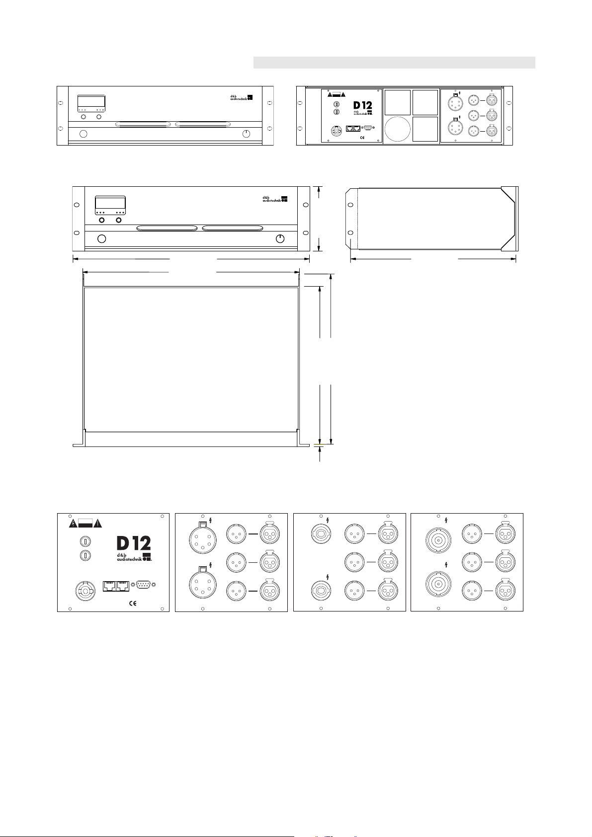
7.1. Technical drawings
D12
LEVEL
PUSH MENU
MUTE
POWER
A
B
ON
OFF
OVLGRISPOVLGRISP
OUT A
OUT B
INPUTLINK
CH B
ANALOG
DIGITAL
AES/EBU
CH A
ANALOG
SERVICEREMOTE
VOLTAGE SEE LABEL
~ 50/60 Hz
1400 W
CAUTION
RISK OF ELECTRIC SHOCK
DO NOT OPEN
www.dbaudio.com
MAINS SUPPLY
RISK OF FIRE - REPLAC E FUSE AS MA RKED
T10A H / 250 V
FUSE
T10A H / 250 V
FUSE
Made in Germany
348 [13.70"]
328 [12.91"]
483 [19.00"]
443 [17.44"]
338 [13.31"]
132 [5.20"]
5 [0.20"]
D12
LEVEL
PUSH MENU
MUTE
POWER
A
B
ON
OFF
OVLGRISPOVLGRISP
SERVICEREMOTE
VOLTAGE SEE LABEL
~ 50/60 Hz
1400 W
CAUT ION
RISK OF ELE CT RIC SHOCK
DO NOT OPEN
www.dbaudio.com
MAINS SUPPLY
RISK OF FIRE - REPLACE FUSE AS MAR KED
T10A H / 250 V
FUSE
T10A H / 250 V
FUSE
Made in Germany
OUT A
OUT B
INPUTLINK
CH B
ANALOG
DIGITAL
AES/EBU
CH A
ANALOG
INPUTLINK
CH B
ANALOG
DIGITAL
AES/EBU
CH A
ANALOG
OUT A
OUT B
OUT A
OUT B
INPUTLINK
CH B
ANALOG
DIGITAL
AES/EBU
CH A
ANALOG
Fig. 23: D12 front view Fig. 24: D12 rear view
Fig. 25: D12 enclosure dimensions in mm [inch]
Fig. 26: D12 mains panel Fig. 27: D12 I/O panel EP5 Fig. 28: D12 I/O panel NL4 Fig. 29: D12 I/O panel NL8
D12 Amplifier, Hardware manual (4.9 EN) Page 25 of 28
Page 26

8. Manufacturer's declarations
8.1. EU declaration of conformity (CE symbol)
This declaration applies to:
- D12, Z2600.000/001
- D12, Z2600.300/301
manufactured by d&b audiotechnik GmbH.
All products of type D12 starting from variant Z2600.000 are included,
provided they correspond to the original technical version and have not
been subject to any later design or electromechanical modifications.
We herewith declare that said products are in conformity with the
provisions of the respective EC directives including all applicable
amendments.
A detailed declaration is available on request and can be ordered from
d&b or downloaded from the d&b website at
8.2. WEEE Declaration (Disposal)
Electrical and electronic equipment must be disposed of separately from
normal waste at the end of its operational lifetime.
www.dbaudio.com.
Please dispose of this product according to the respective national
regulations or contractual agreements. If there are any further questions
concerning the disposal of this product please contact d&b audiotechnik.
D12 Amplifier, Hardware manual (4.9 EN) Page 26 of 28
Page 27

Page 28

D2012.E.04, 02/2014 © d&b audiotechnik GmbH
d&b audiotechnik GmbH, Eugen-Adolff-Str. 134, D-71522 Backnang, Germany, Phone +49-7191-9669-0, Fax +49-7191-95 00 00_______
 Loading...