

Page 1
27S-SUB/27A-SUB Manual (1.2 EN)
Page 2

General information
27S-SUB/27A-SUB Manual
Version: 1.2 EN, 12/2011, D2614.EN .01
Copyright © 2011 by d&b audiotechnik GmbH; all rights
reserved.
Keep this manual with the product or in a safe place
so that it is available for future reference.
When reselling this product, hand over this manual to the new
customer.
d&b audiotechnik GmbH
Eugen-Adolff-Strasse 134, D-71522 Backnang, Germany
T +49-7191-9669-0, F +49-7191-95 00 00
docadmin@dbaudio.com, www.dbaudio.com
Page 3

Contents
1. Safety precautions......................................................... 4
1.1. Information regarding the use of loudspeakers......... 4
2. 27S-SUB/27A-SUB loudspeaker............................... 5
2.1. Product description...................................................... 5
2.2. Connections................................................................. 6
2.3. Operation.................................................................... 7
2.3.1. Controller settings.................................................... 7
2.4. Technical specifications............................................... 8
3. Manufacturer's Declarations...................................... 9
3.1. EU conformity of loudspeakers (CE symbol)............. 9
3.2. WEEE Declaration (Disposal)..................................... 9
d&b 27S-SUB/27A-SUB Manual (1.2 EN) 3
Page 4

1. Safety precautions
1.1. Information regarding the use of loudspeakers
Potential risk of personal injury
Never stand in the immediate vicinity of loudspeakers driven at a
high level. Professional loudspeaker systems are capable of
causing a sound pressure level detrimental to human health.
Seemingly non-critical sound levels (from approx. 95 dB SPL) can
cause hearing damage if people are exposed to it over a long
period.
In order to prevent accidents when deploying loudspeakers on the
ground or when flown, please take note of the following:
– When setting up the loudspeakers or loudspeaker stands,
make sure they are standing on a firm surface. If you place
several systems on top of one another, use straps to secure
them against movement.
– Only use accessories which have been tested and approved
by d&b for assembly and mobile deployment. Pay attention to
the correct application and maximum load capacity of the
accessories as detailed in our specific "Mounting instructions"
or in our "Flying system and Rigging manuals".
– Ensure that all additional hardware, fixings and fasteners used
for installation or mobile deployment are of an appropriate
size and load safety factor. Pay attention to the manufacturers'
instructions and to the relevant safety guidelines.
– Regularly check the loudspeaker housings and accessories for
visible signs of wear and tear, and replace them when
necessary.
– Regularly check all load bearing bolts in the mounting devices.
Potential risk of material damage
Loudspeakers produce a static magnetic field even if they are not
connected or are not in use. Therefore make sure when erecting
and transporting loudspeakers that they are nowhere near
equipment and objects which may be impaired or damaged by an
external magnetic field. Generally speaking, a distance of 0.5 m
(1.5 ft) from magnetic data carriers (floppy disks, audio and video
tapes, bank cards, etc.) is sufficient; a distance of more than 1 m
(3 ft) may be necessary with computer and video monitors.
d&b 27S-SUB/27A-SUB Manual (1.2 EN)4
Page 5

2. 27S-SUB/27A-SUB loudspeaker
2.1. Product description
The 27S-SUB and 27A-SUB are compact high performance
cardioid subwoofers for use with d&b xS-Series and xA-Series
loudspeakers. The cabinets house two long excursion neodymium
drivers in an integrated cardioid setup: a 15“ driver in a bassreflex design facing to the front and a 12” driver in a two chamber
bandpass design radiating to the rear. The arrangement and
tuning provide a cardioid dispersion pattern using a single
amplifier channel.
The 27A-SUB incorporates the same acoustic components as the
27S-SUB, however, the cabinet is equipped with an integrated
rigging system for the design of vertical arrays. The 27A-SUB can
be combined with 10A and 10AL loudspeakers.
The frequency response extends from 40 Hz to 140/100 Hz.
The enclosures are constructed from marine plywood with an
impact resistant black paint finish. The fronts of the cabinets are
protected by a rigid metal grill backed by an acoustically
transparent foam.
The 27S-SUB is equipped with four rubber feet to prevent cabinet
movement and protect the bottom panel against scratching.
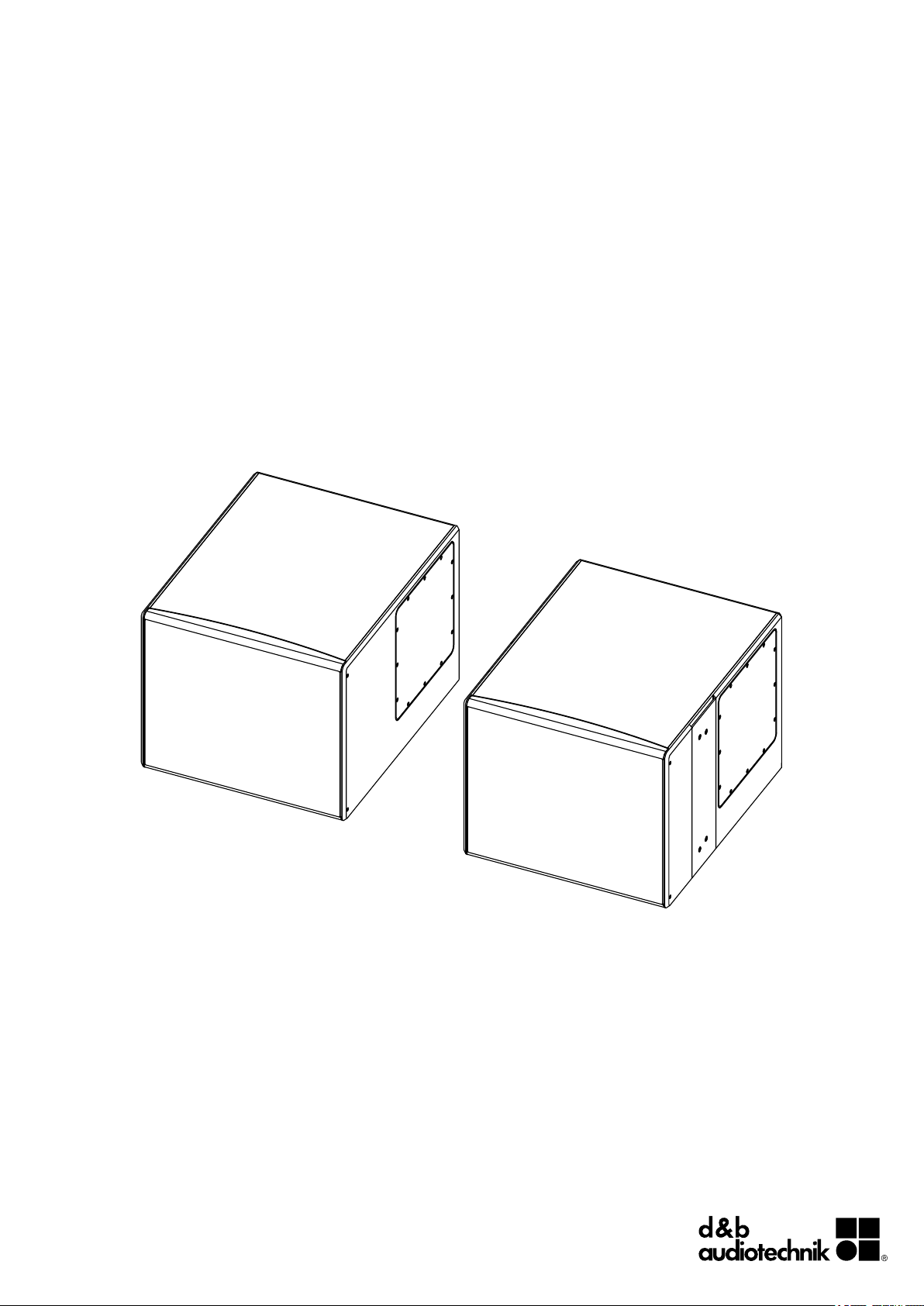
Fig. 1: 27S-SUB/27A-SUB loudspeaker
Rigging examples:
27S-SUB ceiling mounted with Z5410 Horizontal bracket 18S/27S.
10AL/27A-SUB array.
Fig. 2: Cardioid dispersion pattern
The cabinets are Ball Impact Resistant according to DIN 18032-3.
Cardioid dispersion
Cardioid dispersion avoids unwanted energy behind the system
and greatly reduces the reverberant field at low frequencies
providing highest accuracy in low frequency reproduction. 27S
and 27A subwoofers can be used as stand-alone systems or in
stacked or flown combinations with a minimum distance of 60 cm
(2 ft) between adjacent cabinets or to side walls. When set up in
front of walls, the minimum distance from the cabinet rear panel to
the wall is 15 cm (0.5 ft).
27S-SUB rigging components
The 27S-SUB side panels are each equipped with a pair of M10
threads to accept the Z5410 Horizontal bracket 18S/27S. The
threaded inserts are covered by dummy caps in cabinet color. The
caps must be removed before mounting any accessories.
27A-SUB rigging components
27A-SUB cabinets are connected to form a vertical array each
using the Z5418 Connector plates xA-SUB. Up to four 27A-SUB
cabinets can be connected. When integrated at the top of a 10A
or 10AL array, up to two 27A-SUB cabinets can be combined with
up to six 10A/10AL cabinets.
d&b 27S-SUB/27A-SUB Manual (1.2 EN) 5
Page 6
Vertical arrays are supported using the Z5414 Flying bar xA and
the Z5413 Flying bar connector plates xA. For approved
configurations as well as safety and mounting instructions, refer to
the respective rigging manual.
Cabinet options
The weather resistant version (WR) is suitable for outdoor use
(IP34, vertical aiming up to 0°). The cabinets have an impact and
weather protected black PCP (Polyurea Cabinet Protection) finish.
2.2. Connections
The cabinets are fitted with a pair of NL4 connectors and a two
pole screw terminal block (ST). All four pins of both NL4
connectors are wired in parallel. The cabinets use the pin
assignments 2+/2–. Pins 1+/1– are designated to full range
cabinets.
Cabinets with the weather resistant option (WR) are equipped with
a fixed input cable (PG type, H07-RN-F, 2 x 2.5 mm2 (AWG 13),
standard length 5.5 m (18 ft).
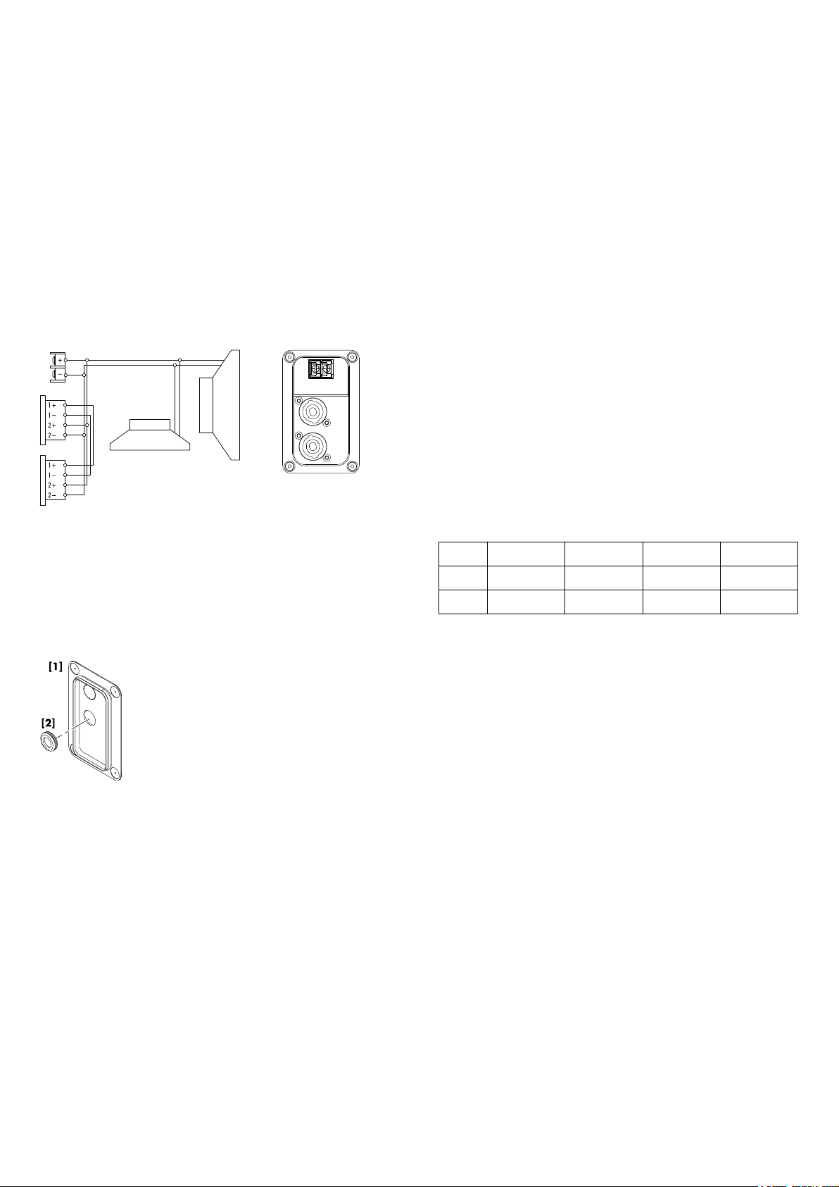
Fig. 3: Connector wiring
Fig. 4: Cover plate and rubber grommet
Pin equivalents of the applicable connector options are listed in the
table below.
NL4
ST
PG
1+ 1– 2+ 2–
n.a. n.a. + –
n.a. n.a. Brown (+) Blue (–)
Fixed cable connection
The 27S-SUB and 27A-SUB loudspeakers are each supplied with
a cover plate [1] and a rubber grommet feed through [2]. For
indoor operation, these items can be used to hide the connector
panel, if required. For unprotected outdoor operation, the
connector panel must be covered, i.e. both items must be used to
achieve an IP degree of protection of IP34.
To install the fixed cable connection, proceed as follows:
Tools required: Philips screw driver (#PH2).
1. Prepare the rubber grommet and the connection cable.
2. Remove the knockout opening in the cover plate and attach
the rubber grommet correspondingly.
3. Insert the connection cable through the rubber grommet and
connect the cable wires to the screw terminal.
Þ Observe the correct polarity!
4. Undo the four screws of the connector panel.
5. Push the cover plate towards the connector panel until it fits
into place.
6. Finally fix the cover plate together with the connector panel
using the four screws.
d&b 27S-SUB/27A-SUB Manual (1.2 EN)6
Page 7

Fig. 5: Installing the fixed cable connection
NL4 connection with cover plate
The two NL4 connector sockets of the cabinet's connector panel
are located in a recess to allow the use of the cover plate [1]
together with NL4 cable connectors, as shown in the graphic
opposite.
Fig. 6: NL4 cable connection with cover plate [1]
Note: Neutrik NL4FC type connectors must be used for this
option.
The cover plate is equipped with two knockout openings to allow
daisy chaining of the loudspeaker.
To use the NL4 connection, proceed in the same manner as
described above in the section entitled Þ "Fixed cable connection"
on page 6.
2.3. Operation
NOTICE!
Only operate d&b loudspeakers with a correctly configured d&b
amplifier, otherwise there is a risk of damaging the loudspeaker
components.
Operation with D6 or D12
Select the controller setup 27S-SUB for 27S or 27A subwoofers.
Within the D12 amplifier it is available in "Dual Channel" and "Mix
TOP/SUB" mode. For combinations with full range systems fed by
a single 4-wire cable "Mix TOP/SUB" mode must be selected.
Up to a total of two 27S-SUB or 27A-SUB loudspeakers can be
driven by each channel of the D6 or D12 amplifiers.
2.3.1. Controller settings
For acoustic adjustment the 100 Hz function can be selected.
100 Hz circuit
If the 100 Hz circuit is selected, the upper operating frequency of
the system is reduced from 140 Hz to 100 Hz.
d&b 27S-SUB/27A-SUB Manual (1.2 EN) 7
Page 8
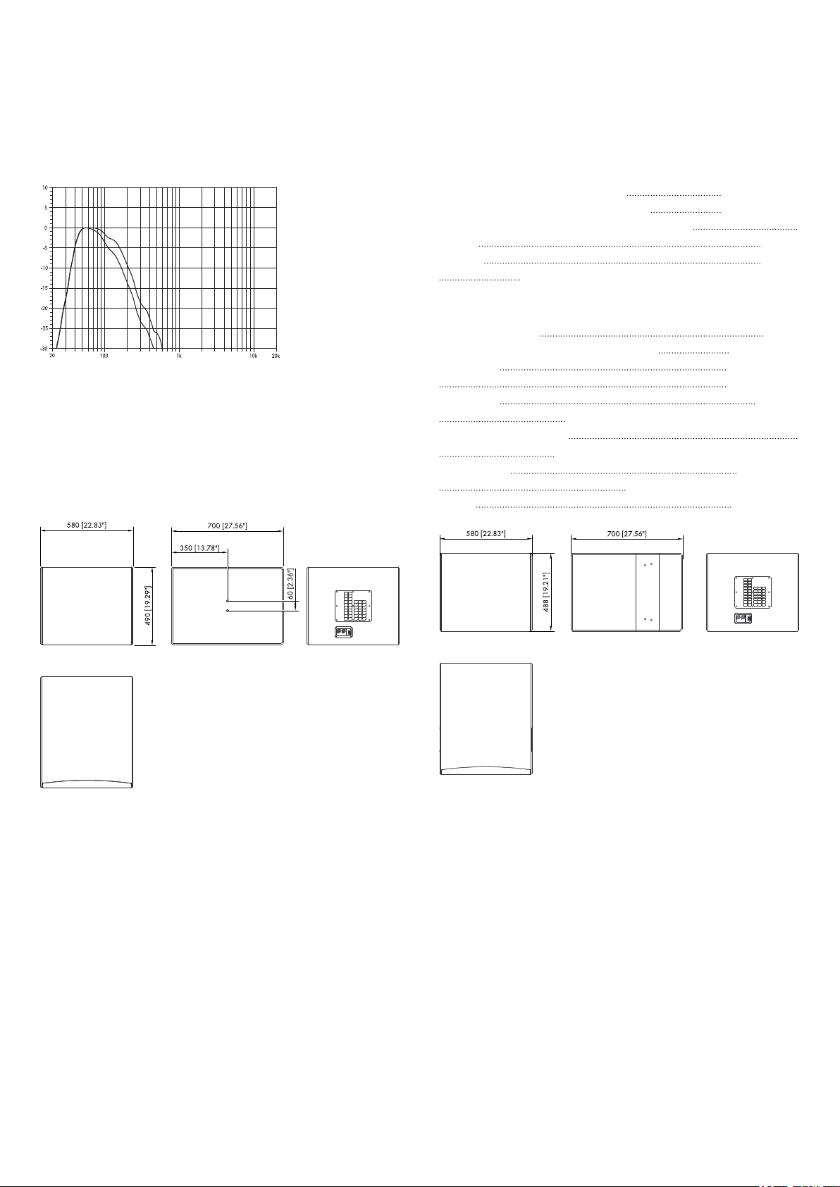
Fig. 7: 27S-SUB/27A-SUB frequency response,
standard and 100 Hz mode
2.4. Technical specifications
27S-SUB/27A-SUB system data
Frequency response (–5 dB standard)
Frequency response (–5 dB 100 Hz mode) 40 Hz - 100 Hz
Max. sound pressure (single cabinet, 1 m, free field)
with D6 128 dB
with D12 131 dB
(SPLmax peak, pink noise test signal with crest factor of 4)
40 Hz - 140 Hz
27S-SUB/27A-SUB loudspeaker
Nominal impedance
Power handling capacity (RMS/peak 10 ms) 500/2000 W
Components 1 x 15“ driver
Connections 2 x NL4
1 x screw terminal (ST - up to 4 mm2/AWG 11)
Optional fixed cable (PG):
H07-RN-F, 2 x 2.5 mm2 (AWG 13), 5.5 m (18 ft)
Pin assignment NL4: 2+/2–
Fixed cable (PG): brown + / blue –
Weight 41 kg (90 lb)
6 ohms
1 x 12“ driver
Fig. 8: 27S-SUB cabinet dimensions in mm [inch]
Fig. 9: 27A-SUB cabinet dimensions in mm [inch]
d&b 27S-SUB/27A-SUB Manual (1.2 EN)8
Page 9

3. Manufacturer's Declarations
3.1. EU conformity of loudspeakers (CE symbol)
This declaration applies to:
d&b 27S-SUB loudspeaker, Z1580
d&b 27A-SUB loudspeaker, Z1581
manufactured by d&b audiotechnik GmbH.
All production versions of these types are included, provided they
correspond to the original technical version and have not been
subject to any later design or electromechanical modifications.
We herewith declare that said products are in conformity with the
provisions of the respective EC directives including all applicable
amendments.
A detailed declaration is available on request and can be ordered
from d&b or downloaded from the d&b website at
www.dbaudio.com.
3.2. WEEE Declaration (Disposal)
Electrical and electronic equipment must be disposed of separately
from normal waste at the end of its operational lifetime.
Please dispose of this product according to the respective national
regulations or contractual agreements. If there are any further
questions concerning the disposal of this product, please contact
d&b audiotechnik.
d&b 27S-SUB/27A-SUB Manual (1.2 EN) 9
Page 10

D2614.EN .01, 12/2011 © d&b audiotechnik GmbH
www.dbaudio.com
 Loading...