

Page 1
24C/24C-E
xC
Manual 1.3 en
Page 2

General information
24C/24C-E Manual
Version: 1.3 en, 02/2015, D2618.EN .01
Copyright © 2015 by d&b audiotechnik GmbH; all rights
reserved.
Keep this manual with the product or in a safe place
so that it is available for future reference.
When reselling this product, hand over this manual to the new
customer.
d&b audiotechnik GmbH
Eugen-Adolff-Strasse 134, D-71522 Backnang, Germany
T +49-7191-9669-0, F +49-7191-95 00 00
docadmin@dbaudio.com, www.dbaudio.com
Page 3

Contents
1. Safety precautions......................................................... 4
1.1. Information regarding the use of loudspeakers......... 4
2. 24C / 24C-E cardioid column loudspeaker........... 5
2.1. Product description...................................................... 5
2.1.1. 24C cardioid column loudspeaker......................... 5
2.1.2. 24C-E cardioid column extender............................ 5
2.1.3. Cardioid dispersion................................................. 6
2.1.4. Dispersion characteristics........................................ 7
2.1.5. Directivity index (dB)................................................ 7
2.1.6. Aiming of the beam................................................. 8
2.2. Connections................................................................. 9
2.3. Operation.................................................................... 9
2.3.1. Controller settings.................................................. 10
2.4. Technical specifications............................................ 11
3. Attaching the 24C-E extender.................................. 13
4. Manufacturer's declarations.................................... 15
4.1.
EU conformity of loudspeakers (CE symbol)........... 15
4.2. WEEE Declaration (Disposal).................................. 15
d&b 24C/24C-E Manual 1.3 en 3
Page 4

1. Safety precautions
1.1. Information regarding the use of loudspeakers
Potential risk of personal injury
Never stand in the immediate vicinity of loudspeakers driven at a
high level. Professional loudspeaker systems are capable of
causing a sound pressure level detrimental to human health.
Seemingly non-critical sound levels (from approx. 95 dB SPL) can
cause hearing damage if people are exposed to it over a long
period.
In order to prevent accidents when deploying loudspeakers on the
ground or when flown, please take note of the following:
– When setting up the loudspeakers or loudspeaker stands,
make sure they are standing on a firm surface. If you place
several systems on top of one another, use straps to secure
them against movement.
– Only use accessories which have been tested and approved
by d&b for assembly and mobile deployment. Pay attention to
the correct application and maximum load capacity of the
accessories as detailed in our specific "Mounting instructions"
or in our "Flying system and Rigging manuals".
– Ensure that all additional hardware, fixings and fasteners used
for installation or mobile deployment are of an appropriate
size and load safety factor. Pay attention to the manufacturers'
instructions and to the relevant safety guidelines.
– Regularly check the loudspeaker housings and accessories for
visible signs of wear and tear, and replace them when
necessary.
– Regularly check all load bearing bolts in the mounting devices.
Potential risk of material damage
Loudspeakers produce a static magnetic field even if they are not
connected or are not in use. Therefore make sure when erecting
and transporting loudspeakers that they are nowhere near
equipment and objects which may be impaired or damaged by an
external magnetic field. Generally speaking, a distance of 0.5 m
(1.5 ft) from magnetic data carriers (floppy disks, audio and video
tapes, bank cards, etc.) is sufficient; a distance of more than 1 m
(3 ft) may be necessary with computer and video monitors.
d&b 24C/24C-E Manual 1.3 en4
Page 5
2. 24C / 24C-E cardioid column loudspeaker
2.1. Product description
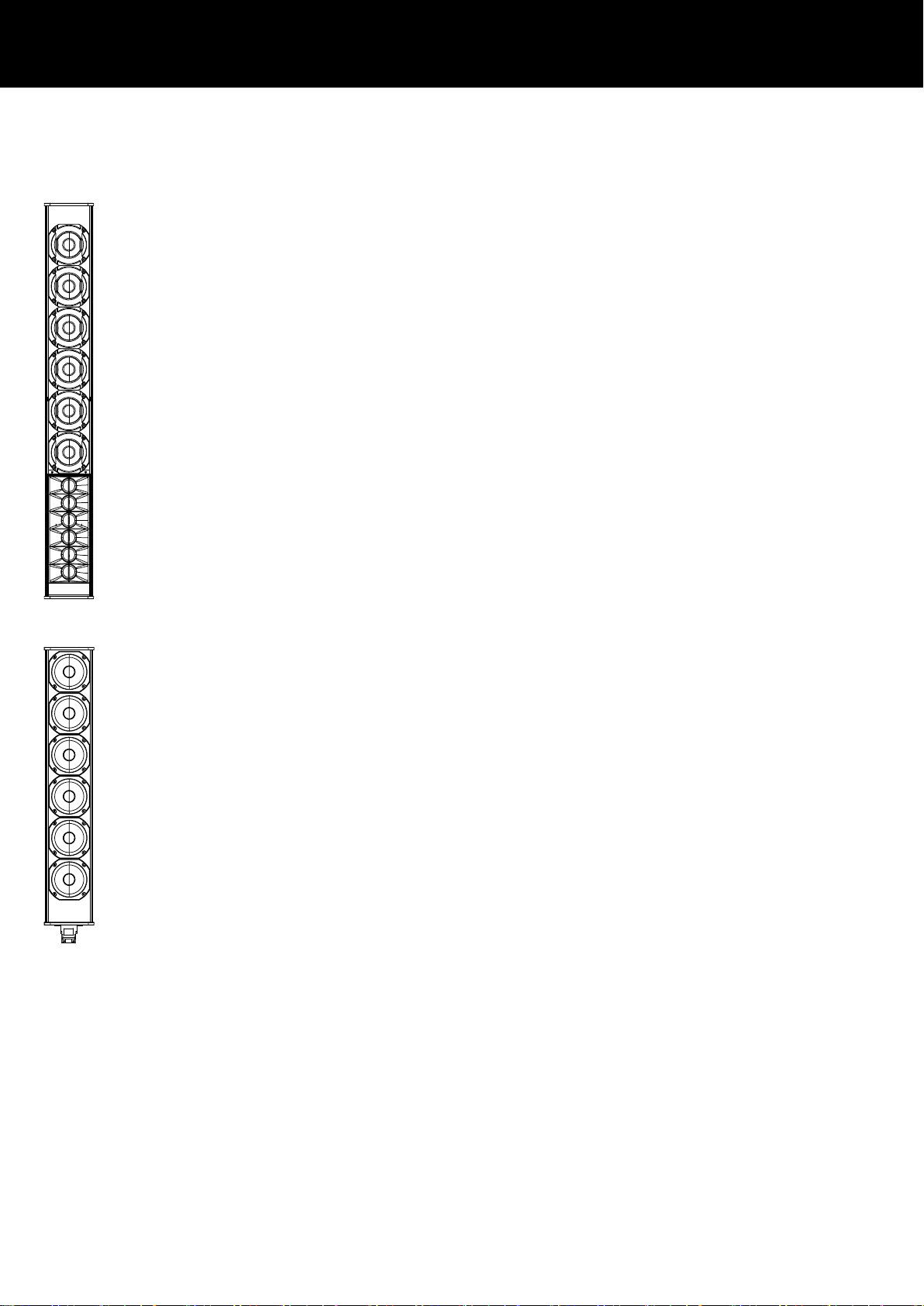
2.1.1. 24C cardioid column loudspeaker
The 24C is a passive 2-way column loudspeaker housing six 4”
neodymium drivers and an HF array comprising six 1.1” dome
tweeters.
The 4" drivers are arranged in a unique cardioid setup radiating
through waveguide elements at the front and damped ports at the
rear of the cabinet. This design provides a constant directivity
pattern of 90° in the horizontal plane with an average broadbad
attenuation to the rear of approx. 18 dB.
In the vertical plane, the beam produced by the low-mid drivers is
tilted downwards by –5° and provides significant directivity down
to 370 Hz.
The HF array has a nominal vertical dispersion of 20° and its main
axis can be adjusted continuously between 0° and –14° (when
using ArrayCalc, adjustment in 1° increments).
The loudspeaker cabinets are based on an extruded aluminum
profile with a metal grill protecting the front of the loudspeaker.
Two continuous rails (8 mm T-slot profiles) are provided at the rear
for attaching a wall mount bracket.
2.1.2. 24C-E cardioid column extender
The 24C-E is a passive column extension to be attached directly to
the 24C. The cabinet houses six 4” neodymium drivers, providing
an extension of vertical directivity down by a further octave to
190 Hz.
The acoustic design is based on the same principles as the 24C,
thus offering the same cardioid dispersion pattern in the horizontal
plane. The extender is electrically connected through the 24C
without the need for an additional amplifier channel.
Note: The 24C-E loudspeaker is not intended to be operated
as a stand-alone system.
d&b 24C/24C-E Manual 1.3 en 5
Page 6
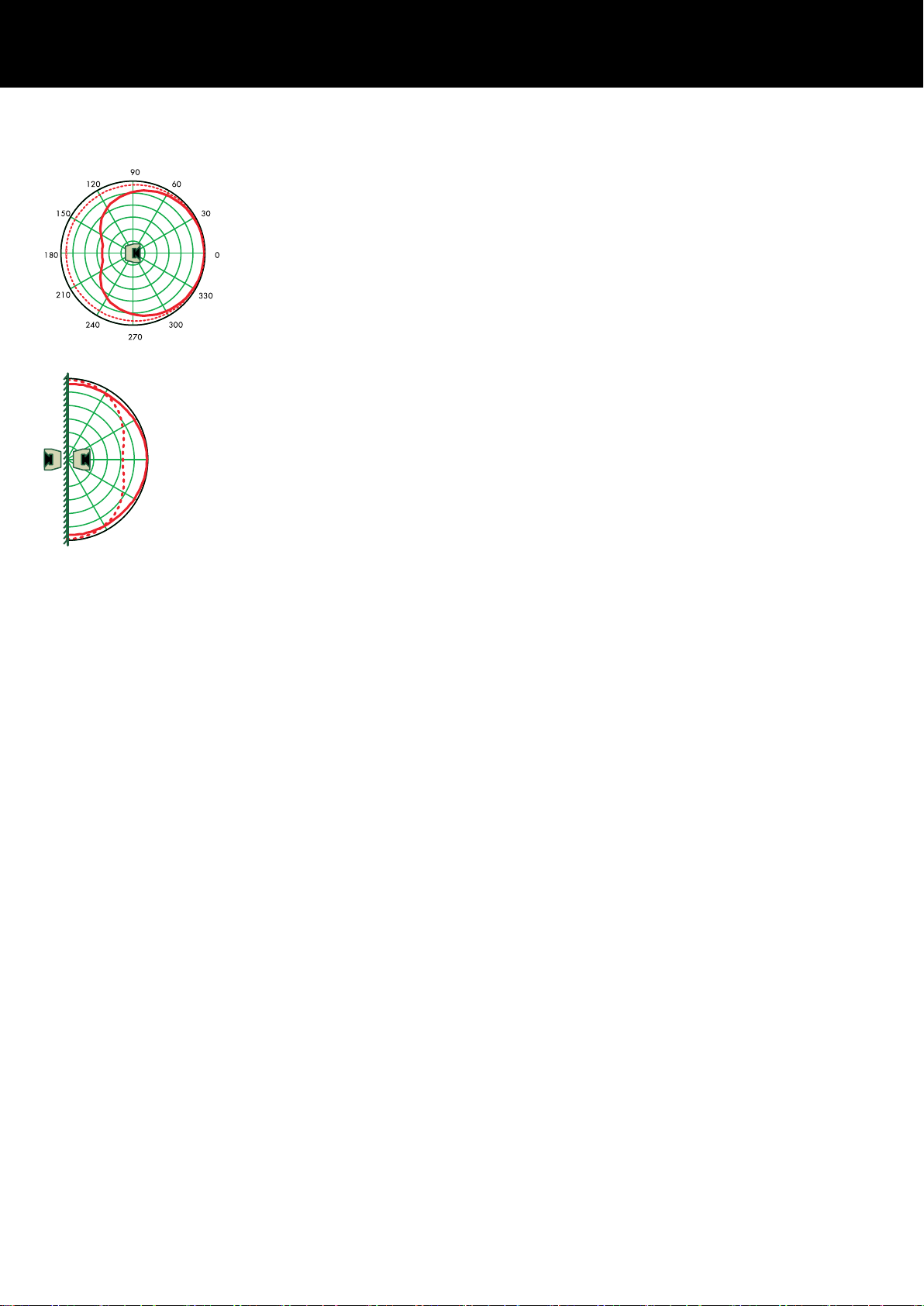
2.1.3. Cardioid dispersion
Due to their dimensions, conventional column loudspeakers
provide no significant horizontal directivity below 2 kHz.
At low and mid frequencies, the resulting polar pattern is almost
omni-directional (dotted line).
The cardioid patterns of the 24C and 24C-E show a much higher
directivity resulting in much less energy radiated into the room
(continuous line).
Typically, column loudspeakers are mounted onto walls or other
hard plane surfaces. Hard surfaces act as an acoustic mirror. That
means, the room is not only covered by the sound of the actual
column loudspeaker but also by the sound produced by its virtual
mirror source from "behind".
In the case of conventional column loudspeakers with their low
horizontal directivity, the mirror source radiates at a similar level as
the loudspeaker itself.
The combination of both sources results in a dipolar characteristic
where the main energy is radiated along the walls (dotted line).
The 24C and 24C-E, however, with their cardioid dispersion
patterns provide an even dispersion characteristic and a useful
directivity when mounted onto a wall.
2.1.3.1. Flush mounting
If architecturally required, xC-Series cabinets may be partially flush
mounted.
Please note that this will render the cardioid ports ineffective and
as a result, may change the dispersion pattern.
In conjuntion with 24C cabinets, care must also be taken to ensure
that the dispersion of the rearmost horn of the HF array is not
obstructed by the edges of the wall recess. Otherwise, this will
create reflections which will have a negative impact on the
frequency response in front of the cabinet. The same applies when
the cabinet is mounted in a corner of the room. Reflections of the
adjacent side walls will cause deviations in both, the frontal
frequency response and the dispersion pattern.
d&b 24C/24C-E Manual 1.3 en6
Page 7
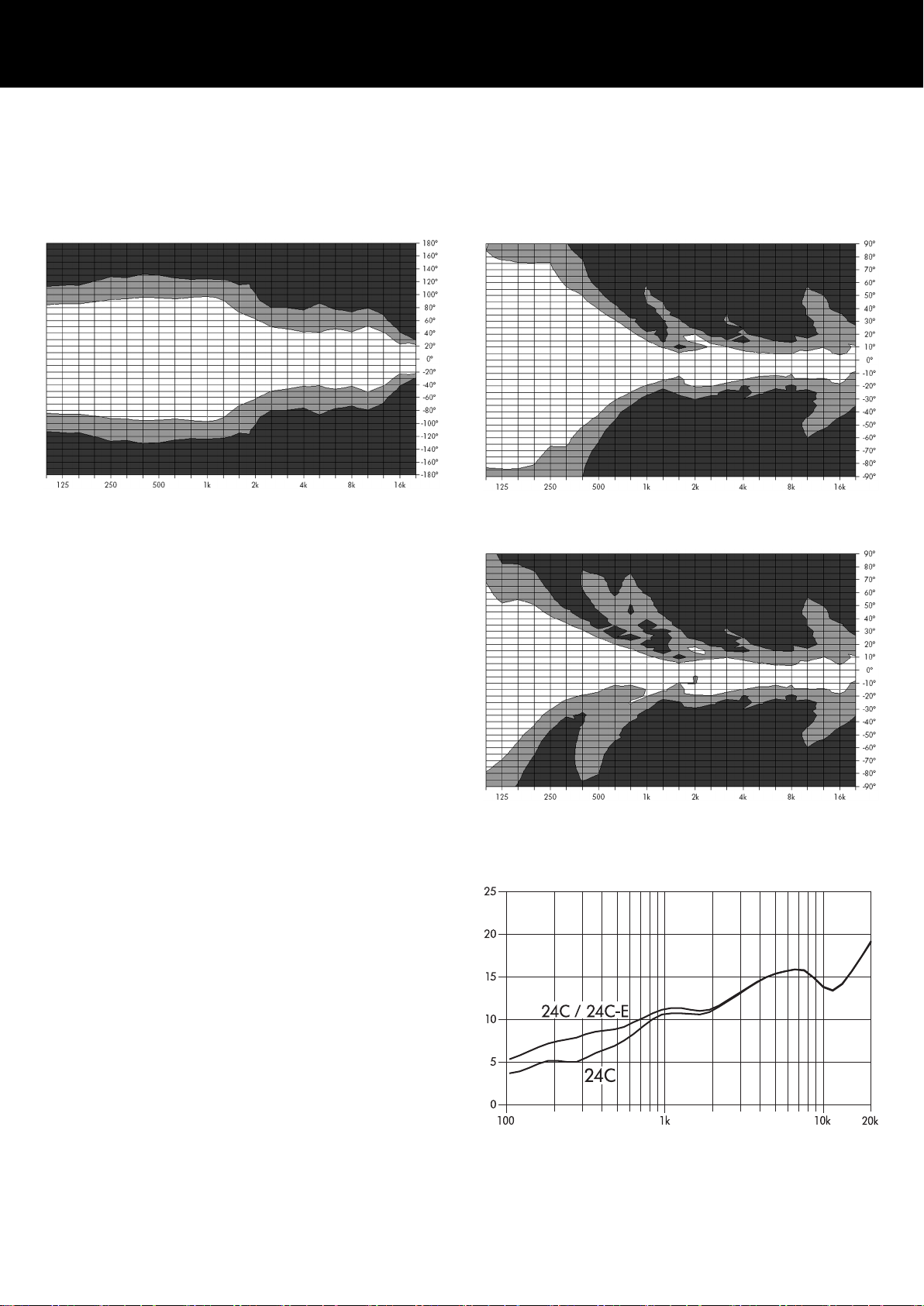
2.1.4. Dispersion characteristics
The following graphs show dispersion angle over frequency of a
single cabinet plotted using lines of equal sound pressure (isobars)
at –6 dB and –12 dB.
Isobar diagram 24C horizontal
Isobar diagram 24C vertical
Isobar diagram 24C with 24C-E vertical
2.1.5. Directivity index (dB)
d&b 24C/24C-E Manual 1.3 en 7
Page 8

2.1.6. Aiming of the beam
The aiming of the beam of the HF array can be adjusted between
0° and –14°.
The DMAX/H scale on the left provides a simple means of
determining the correct setting for a given room geometry. The
assumption here is the listening plane is horizontal and the
loudspeaker column is mounted exactly vertically.
Simply take the maximum distance to be covered (DMAX) and
divide it by the height (H) above the listeners' ears up to the bottom
edge of the cabinet. Set the mark to the respective DMAX/H value.
Example:
A seated audience has a typical ear height of 1.20 m (4 ft)
above ground level. The bottom edge of the loudspeaker is at
2.70 m (9 ft) above ground level, i.e. 1.50 m (5 ft) above ear
level. The maximum distance to be covered is 18 m (60 ft).
The HF beam has therefore to be set to:
18 m / 1.50 m = 12 (60 ft / 5 ft =12)
To aim the beam, proceed as follows:
HF beam set to DMAX/H = 12
Tools required: 10 mm (1/4") wrench/spanner
1. At the rear, slacken the M6 hex head screw.
2. Slide the screw up or down to set the mark above the screw to
the calculated value.
3. Carefully retighten the screw.
d&b 24C/24C-E Manual 1.3 en8
Page 9
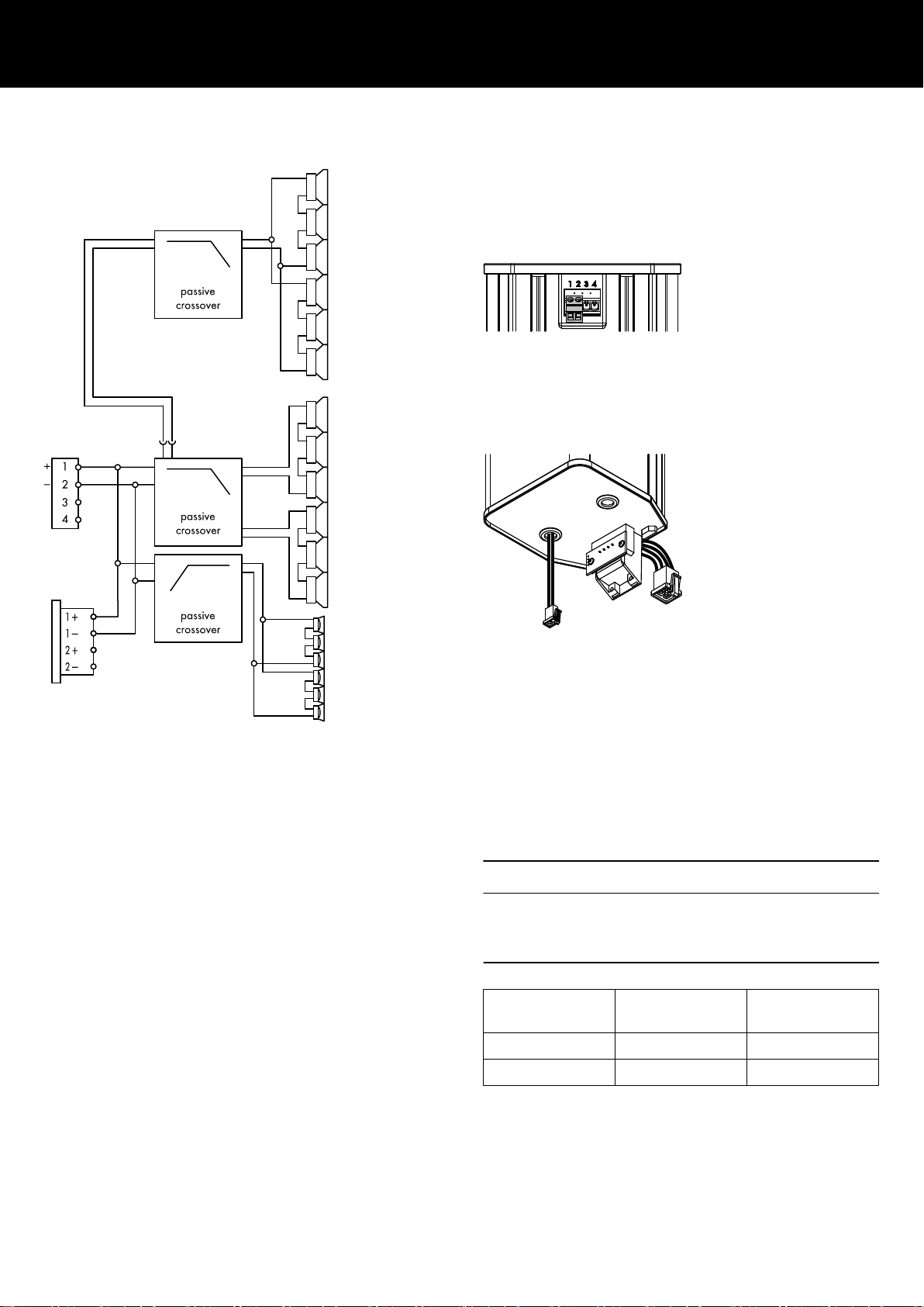
2.2. Connections
24C cabinets are fitted with a 4-pole Phoenix Euroblock connector
block accepting a 2-pole Phoenix Euroblock screw terminal
connector (cross-section up to 4 mm2/AWG 11). The connector
uses the pin assignments 1: + and 2: —. Pins 3 and 4 are not
connected.
In addition, an NL4 M connector is provided using the pin
assignment 1+/1–.
24C-E cabinets are equipped with a fixed cable gland fitted with a
2-pole Mate-N-Lok mini connector. The extender is electrically
connected through the 24C cabinet.
Connector wiring
In addition, 24C-E cabinets are also equipped with the same 4pole Phoenix Euroblock connector block and the corresponding
input connector cable as the 24C cabinets to allow quick and easy
attachment of the extender to the 24C cabinet.
A detailed description of how to attach and connect the extender
is given in Þ Chapter 3. "Attaching the 24C-E extender"
on page 13.
2.3. Operation
NOTICE!
Only operate d&b loudspeakers with a correctly configured d&b
amplifier, otherwise there is a risk of damaging the loudspeaker
components.
Application Setup Cabinets per
channel
24C 24C 2
24C with 24C-E 24C-E 1
For applicable amplifiers, the controller setups are available in
Dual Channel and Mix TOP/SUB mode.
d&b 24C/24C-E Manual 1.3 en 9
Page 10

-5
0
5
10
-10
-15
-20
-25
-30
20
100 1k 10k
20k
Frequency response correction of HFA circuit
2.3.1. Controller settings
For acoustic adjustment the functions CUT, HFA and CPL can be
selected.
CUT circuit
Set to CUT, the cabinet low frequency level is reduced. The
cabinets are now configured for use with actively driven d&b
subwoofers.
HFA circuit
In HFA mode (High Frequency Attenuation), the HF response of the
system is rolled off. HFA provides a natural, balanced frequency
response when a unit is placed close to listeners in near field or
delay use.
High Frequency Attenuation begins gradually at 1 kHz, dropping
by approximately 3 dB at 10 kHz. This roll off mimics the decline
in frequency response experienced when listening to a system from
a distance in a typically reverberant room or auditorium.
Frequency response correction of CPL circuit
CPL circuit
The CPL (Coupling) circuit compensates for different acoustic
properties of the venue. CPL begins gradually around 1 kHz, with
the maximum attenuation below 250 Hz. To achieve a balanced
frequency response, the CPL circuit can be set to dB attenuation
values between 0 and –9.
Positive CPL values create an adjustable low frequency boost (0 to
+5 dB) and can be set when the system is used in full range mode
without subwoofers.
d&b 24C/24C-E Manual 1.3 en10
Page 11

24C frequency response, standard and CUT modes
2.4. Technical specifications 24C system data
Frequency response (–5 dB standard) 110 Hz - 17 kHz
Frequency response (–5 dB CUT mode) 150 Hz - 17 kHz
Max. sound pressure (1 m, free field) 126 dB
(SPLmax peak, pink noise test signal with crest factor of 4)
24C loudspeaker
Nominal impedance
Power handling capacity (RMS/peak 10 ms) 125/600 W
Nominal dispersion angle (h x v) 90° x 20°
Vertical aiming of low-mid beam –5°
Vertical adjustment of HF array 0° to –14°
Components 6 x 4“ driver with neodymium magnet
6 x 1.1“ dome tweeter mounted in vertical horn array
Passive crossover network
Connections 4-pin Phoenix Euroblock and 1 x NL4 M
Pin assignment Phoenix: 1: + / 2: — (3/4: n.c.)
Enclosure Extruded aluminum, metal baffle and front grill
Weight 9 kg (19.8 lb)
Mounting Dual-rail 8 mm T-slot profile at the rear
12 ohms
NL4 M: 1+/1–
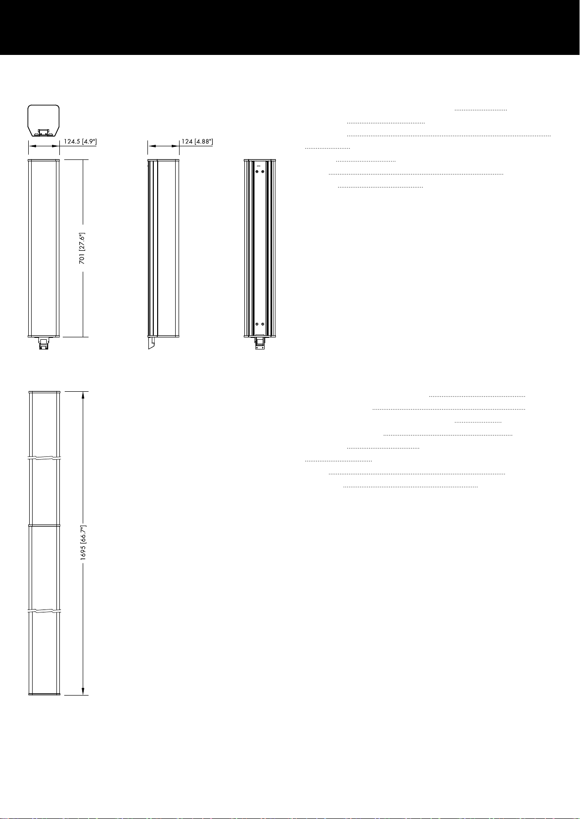
24C cabinet dimensions in mm [inch]
d&b 24C/24C-E Manual 1.3 en 11
Page 12
24C-E loudspeaker
Power handling capacity (RMS/peak 10 ms) 125/600 W
Components 6 x 4“ driver with neodymium magnet
Connections
Fixed cable gland with 2-pole Mate-N-Lok mini through 24C
Enclosure Extruded aluminum, metal baffle and front grill
Weight 7 kg (15.4 lb)
Mounting Dual-rail 8 mm T-slot profile at the rear
24C-E cabinet dimensions in mm [inch]
24C loudspeaker with 24C-E extender
Max. sound pressure (1 m, free field)
Nominal impedance 6 ohms
Power handling capacity (RMS/peak 10 ms) 250/1200 W
Dispersion angle (h x v) 90° x 20°
Components 12 x 4“ driver with neodymium magnet
6 x 1.1“ dome tweeter mounted in vertical horn array
Weight 16 kg (35 lb)
Total height 1695 mm (66.7 inch)
128 dB
d&b 24C/24C-E Manual 1.3 en12
Page 13
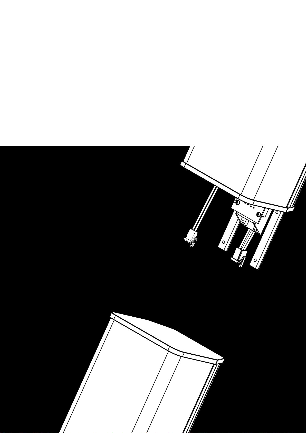
3. Attaching the 24C-E extender
Tools required
– Torx wrench / screwdriver size #TX20
– Torx wrench / screwdriver size #TX15
Remarks
The assembly may be carried out by a single person. However, we
recommend a second person for assistance. Proceed as follows:
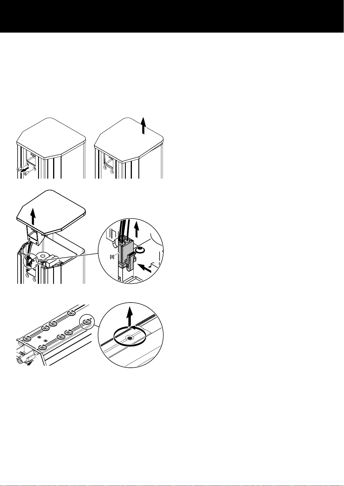
1. Preparing the 24C cabinet
1. At the rear of the cabinet, undo the two countersunk screws
(torx #T20) for the top panel.
2. Slightly lift the front part of the top panel.
3. Lift the back part of the top panel out of its guiding slot.
4. Disconnect the input connector [I] and take off the top panel.
2. Preparing the 24C-E cabinet
1. At the rear of the 24C-E cabinet, slacken the eight fixing
screws (set screws - #T15) of the connecting rails.
d&b 24C/24C-E Manual 1.3 en 13
Page 14

2. Pull out the two connecting rails half their lengths.
3. Retighten the four remaining fixing screws on the extender.
3. Joining the cabinets
1. While a second person renders assistance, insert the
connecting rails of the 24C-E cabinet into the T-slot profiles at
the rear of the 24C cabinet approx. 10 - 20 mm.
2. Reconnect the input connector [I].
3. Push the Mate-N-Lok plug [E] of the extender into the
respective connecting socket, as shown in the graphic
opposite.
4. Fully insert the connecting rails into the T-slot profiles.
Ensure that no connecting wire is crushed between the
Þ
edges of the cabinets.
Ensure that the connecting panel of the extender is fully
inserted.
The connecting panel is fully inserted when the front grill of
the 24C cabinet is properly fitted into the panel and the
threaded inserts [T] are in line with the countersunk drills of
the 24C cabinet.
5. Refit and tighten the two countersunk screws (torx #T20).
6. Tighten the remaining four fixing screws (set screw - torx #T15)
of the connecting rails on the 24C cabinet.
d&b 24C/24C-E Manual 1.3 en14
Page 15

4. Manufacturer's declarations
4.1. EU conformity of loudspeakers (CE symbol)
This declaration applies to:
d&b 24C loudspeaker, Z1700
d&b 24C-E loudspeaker, Z1710
manufactured by d&b audiotechnik GmbH.
All production versions of these types are included, provided they
correspond to the original technical version and have not been
subject to any later design or electromechanical modifications.
We herewith declare that said products are in conformity with the
provisions of the respective EC directives including all applicable
amendments.
A detailed declaration is available on request and can be ordered
from d&b or downloaded from the d&b website at
www.dbaudio.com.
4.2. WEEE Declaration (Disposal)
Electrical and electronic equipment must be disposed of separately
from normal waste at the end of its operational lifetime.
Please dispose of this product according to the respective national
regulations or contractual agreements. If there are any further
questions concerning the disposal of this product, please contact
d&b audiotechnik.
d&b 24C/24C-E Manual 1.3 en 15
Page 16

Page 17

D2618.EN .01, 02/2015 © d&b audiotechnik GmbH
www.dbaudio.com
 Loading...