

Daxten SCOUTUTP Installation Manual

Installation guide

Specifications
Part No’s Switches CPU Adaptors
1018-108 SCOUTutp 8 port Switch 2364-01P SCOUTutp PS/2 CPU adapter
1018-116 SCOUTutp 16 port Switch 2364-01U SCOUTutp USB CPU adapter
2364-01S SCOUTutp SUN CPU adapter
SCOUTutp Height Width Depth Weight
SCOUTutp 8 port 4.15cm / 1.63” 21.5cm / 8.46” 12.20cm / 4.80” 0.92 kg / 2.0 lb
SCOUTutp 16 port 4.15cm / 1.63” 21.5cm / 8.46” 12.20cm / 4.80” 0.92 kg / 2.0 lb
Operating Temperature: 0~40° C ( 32 ~ 104° F)
Storage Temperature: -40~70° C (-40 ~ 158° F)
Humidity: 80% RH non-condensing
Operating Systems DOS, Windows (9X, NT4, 2000, XP, 2003 Server) LINUX, UNIX, QNX,
SGI, FreeBSD, BeOS, Open VMS, Novell, Alpha UNIX, HP UX, SUN
Mouse PS/2, Wheel mouse, Intellimouse, 5-button mouse
Resolution 1600x1200@85Hz
Transmission distance Up to 10m (33ft)
Power supply Internal switching 85-260 VAC 50 / 60 Hz
Connections
System RJ45
Serial RJ11
Local KVM HDD15 / PS/2 - MinDin6 / PS/2 - MiniDin6
CPU Adaptors PS/2 USB SUN
Connections
Video HD15 HD15 HD15
Keyboard/Mouse MiniDin6 USB MiniDin8
System RJ45 RJ45 RJ45
Power From computer’s
Keyboard port
From USB port From computer’s
Keyboard port
Product weight 107g / 0.23lb
Shipping weight 300g / 0.66lb
Dimensions 91 x 41 x 24mm / 3.58 x 1.61 x 0.94”
NOTE: This equipment complies with the requirements of European EMC directive 89/336 EEC in
respect of EN55022 Class B, EN 50082-1 and EN 60555-2.
This equipment has been found to comply with the limits for a Class A digital device, pursuant to
Part 15 of the FCC Rules. These limits are designed to provide reasonable protection against
harmful interference when the equipment is operated in a commercial environment. This
equipment generates, uses, and can radiate radio frequency energy and, if not installed and used
in accordance with the instruction manual, may cause harmful interference to radio
communications. Operation of this equipment in a residential area is likely to cause harmful
interference in which case the user will be required to correct the interference at his own expense.
© Copyright 2004. All rights reserved.
Daxten, the Daxten logo, SCOUTutp and The Brains Behind KVM Switching and Sharing are trademarks of Daxten Industries.
All other trademarks acknowledged.
Revision 1.1

SCOUTutp
Introduction
Thank you for purchasing the SCOUTutp KVM Switch. This product will ensure easy and accurate
control over 8 – 16 PCs from a single console. The SCOUTutp is compatible with PS/2, USB and SUN
style computers with its specific adapters. It has keyboard and mouse emulation for error free bootups and supports a wide variety of mice including the Microsoft Intellimouse. The SCOUTutp supports
high resolutions of up to 1600 x 1200 without any deterioration of the image quality. Switching
between PCs can be accomplished through keyboard Hot Key commands, the front panel or through
the OSD (On-Screen-Display).
Product Features
¾ Allows a user to control 8 - 16 computers from one console.
¾ Supports PS/2, USB and SUN computers through an adapter for each platform
¾ 1U Rack mountable
¾ Distance between console and computer can be up to 10m with simple CAT5 cabling
¾ No drivers or additional software are required for operation.
¾ Keyboard and mouse emulation allows for error free boot-up.
¾ Supports video resolutions of up to 1600 x 1200 @ 85Hz.
¾ Supports VGA, SVGA and XGA monitors.
¾ Keyboard Hot Key, OSD control or the front panel.
¾ Comes with Auto-Scan mode for convenient automatic switching.
¾ Front panel status LEDs give a clear indication of the active PC.
Installation
Before connecting your computers and console devices to the SCOUTutp switch, please ensure that
all devices are powered off.
1. Connecting the console devices with SCOUTutp:
Connect your monitor’s HD 15-pin connector to the SCOUTutp’s Monitor connector on
the rear panel.
Connect your PS/2 keyboard to the PS/2 keyboard connector (purple) and your PS/2
mouse to the PS/2 mouse connector (green) on the rear panel of the SCOUTutp.
2. Connecting the computers with an UTP patch cable and a PS/2 adapter :
Connect the blue HD 15-pin male connector to the VGA port on your computer.
Connect the purple PS/2 (6-pin Mini DIN) keyboard connector to the PS/2 keyboard
port on your computer.
Connect the green PS/2 (6-pin Mini DIN) mouse connector to the PS/2 mouse port on
your computer.
Connect the UTP cable with the PS/2 adapter and the desired SCOUTutp computer
port.
3. Connecting the computers with an UTP patch cable and a USB adapter:
Connect the blue HD 15-pin male connector to the VGA port on your computer.
Connect the USB connector to a USB port on your computer.
Connect the UTP cable with the USB adapter and the desired SCOUTutp computer
port.
4. Connecting the computers with an UTP patch cable and a SUN adapter:
Connect the blue HD 15-pin male connector to the VGA port on your computer.
Connect the SUN connector to the keyboard & mouse port on your computer.
Connect the UTP cable with the SUN adapter and the desired SCOUTutp computer
port.
5. Power up the SCOUTutp
Using the SCOUTutp
Note: Before switching your computers on, please configure non PS/2 computers
emulation type in the OSD!
The SCOUTutp provides three possibilities to select the desired computer. You may use either the
Select button on the unit, the keyboard Hot Key commands or take advantage of the OSD (OnScreen-Display).
You may notice that the mouse cannot be used for around 1 second when the SCOUTutp switches to
another computer. This is normal and is caused by the synchronization process which ensures that
the mouse operates correctly.
Keyboard Hot Key commands
To send Hot Key commands to the SCOUTutp switch, press and release the Ctrl key twice within 2
seconds. Press a command key for the desired effect. The following commands are supported:
First Key Second Key Command Key Confirmation Key Command Result
Ctrl Ctrl
In Auto-Scan mode, the image shown on the monitor will automatically switch to the next computer.
The delay is user definable
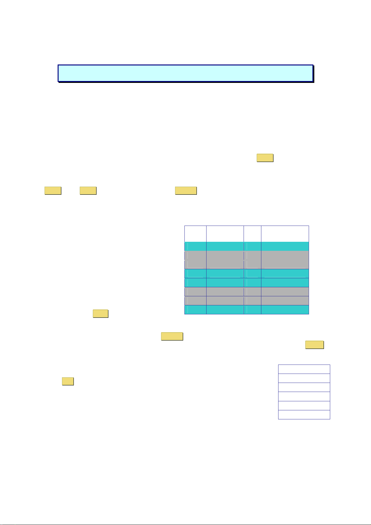
OSD (On-Screen-Display)
To access the OSD, press the Hot Key twice
and the OSD window appears:
Lines with blue text show active computers, lines
with grey text show inactive computers.
To navigate up and down use the UP and
DOWN arrow keys.
To jump from one column to another (in
Settings) use the Tab key.
After you have selected a computer press Enter . A confirmation label appears showing which
computer you accessed. To exit the OSD or return to a previous window within the OSD press ESC .
Note: When you use the OSD you can’t use the keyboard Hot Keys at the same time.
Port number
Enter
Port
No.
01 SUN 01 C
02 PS/2 1 02 C
03 SCOUT 03 S
04 SUN 04 C
05 PS/2 3 05 C
06 USB 06 C
07 USB 07 C
08 PS/2 4 08 C
Computer
OSD Settings
Press F2 and the setting window will appear.
When the OSD is password protected only the administrator has access to this
window.
Switches to the desired PC
No. C = computer
Name
S = switch
blue
grey
grey
blue
blue
grey
grey
blue
OSD Settings
General
Ports
Time
Users
Security
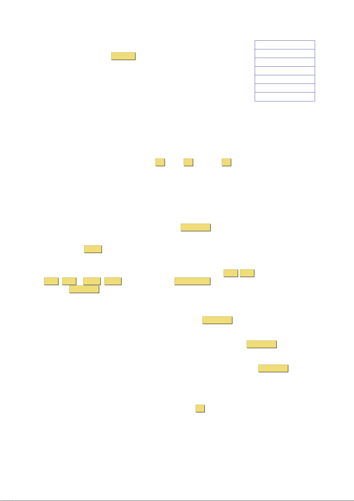
General Settings
Select General and press ENTER , the General Settings window will appear.
From this window you can do the following:
Security
The OSD comes with an advanced password security system with 3 different
security levels. Each security level has different access rights to the system
and have are limited in number as shown below.
General Settings
Security
Hotkey
Autoskip
Serial port
Keyboard language
Switch name
1 x Administrator (Status A)
Set and modify all Passwords and security profiles
Fully access any computer
Access all OSD functions
1 x Supervisor (Status S)
Fully access any computer
Access the following OSD functions only – F4 Scan, F5 Tune and F6 Moving the Confirmation
label.
6 x User (Status U)
Each User has a profile set by the Administrator that defines the access level to different computers.
Activating password protection
Only the Administrator can password-protect or disable the protection of the OSD as follows:
1. Navigate to the Security line and press the Space Bar to toggle between On and Off.
2. The password box appears. Type the Administrators password (default password is
admin).
3. Press Enter
Hot Key
Press the Hot Key and the OSD appears. To change the Hot Key to [Ctrl Ctrl ] (CL on display),
[Ctrl , F11 ], [ Shift , Shift ] (SH on display) or Print Screen.
Press the Space Bar to toggle between the different options. Once selected, press the new Hot Key
to display the OSD in the future.
Autoskip
To access only the active computer lines on the OSD you can use this feature.
To activate the Autoskip toggle between the options with the Space Bar.
Serial port
Serial port ON means the Control Management program can be used. To change the Serial port
settings, navigate to the Serial port line and toggle between the options using Space Bar.
Keyboard language
The default is US English which can be changed to German (DE) or French (FR) as follows:
Navigate to the Keyboard language line and toggle between the options using the Space Bar.
Switch name
You can substitute up to 18 characters in the line. A space constitutes a character. Give each switch’s
OSD a different name.
Factory Default
To return to the factory default Settings you have to press F7 and all changes will be removed.
 Loading...