

Page 1

Galaxy
Cat 5 Video Distribution System
Installation and Operation Manual rev 1.1
TM
Page 2
LIMITED WARRANTY
Daxten warrants the Galaxy™ to be in good working order for one year from the date of purchase from
Daxten or an authorised dealer. Should this product fail to be in good working order at any time during
this one year warranty period, Daxten will, at its option, repair or replace the Unit as set forth below.
Repair parts and replacement units will be either reconditioned or new. All replaced parts become the
property of Daxten. This limited warranty does not include service to repair damage to the Unit
resulting from accident, disaster, abuse, or unauthorised modification of the Unit, including static
discharge and power surges.
Limited Warranty service may be obtained by delivering this unit during the one year warranty period
to Daxten or an authorised repair centre providing a proof of purchase date. If this Unit is delivered by
mail, you agree to insure the Unit or assume the risk of loss or damage in transit, to prepay shipping
charges to the warranty service location, and to use the original shipping container or its equivalent.
You must call for a return authorisation number first. Under no circumstances will a unit be accepted
without a return authorisation number. Contact an authorised repair centre or Daxten for further
information
ALL EXPRESS AND IMPLIED WARRANTIES FOR THIS PRODUCT INCLUDING THE WARRANTIES OF
MERCHANTABILITY AND FITNESS FOR A PARTICULAR PURPOSE, ARE LIMITED IN DURATION TO A
PERIOD OF ONE YEAR FROM THE DATE OF PURCHASE, AND NO WARRANTIES, WHETHER EXPRESS OR
IMPLIED, WILL APPLY AFTER THIS PERIOD. SOME COUNTRIES DO NOT ALLOW LIMITATIONS ON
HOW LONG AN IMPLIED WARRANTY LASTS, SO THE ABOVE LIMITATION MAY NOT APPLY TO YOU.
IF THIS PRODUCT IS NOT IN GOOD WORKING ORDER AS WARRANTED ABOVE, YOUR SOLE REMEDY
SHALL BE REPLACEMENT OR REPAIR AS PROVIDED ABOVE. IN NO EVENT WILL DAXTEN BE LIABLE
TO YOU FOR ANY DAMAGES INCLUDING ANY LOST PROFITS, LOST SAVINGS OR OTHER INCIDENTAL
OR CONSEQUENTIAL DAMAGES ARISING OUT OF THE USE OF OR THE INABILITY TO USE SUCH
PRODUCT, EVEN IF DAXTEN OR AN AUTHORISED DEALER HAS BEEN ADVISED OF THE POSSIBILITY
OF SUCH DAMAGES, OR FOR ANY CLAIM BY ANY OTHER PARTY.
NOTE: This equipment complies with the requirements of European EMC directive 89/336 EEC in
respect of EN55022 Class B, EN 50082-1 and EN 60555-2.
This equipment has been found to comply with the limits for a Class A digital device, pursuant to Part
15 of the FCC Rules. These limits are designed to provide reasonable protection against harmful
interference when the equipment is operated in a commercial environment. This equipment generates,
uses, and can radiate radio frequency energy and, if not installed and used in accordance with the
instruction manual, may cause harmful interference to radio communications. Operation of this
equipment in a residential area is likely to cause harmful interference in which case the user will be
required to correct the interference at his own expense.
© Copyright 2003. All rights reserved.
No part of this manual may be reproduced, stored in a retrieval system, or transcribed in any form or any
means, electronic or mechanical, including photocopying and recording, without the prior written
permission of Daxten.
2
Page 3

Printed in Denmark Revision 1.1
3
Page 4

Page 5
INTRODUCTION
Thank you for choosing the Galaxy ™ system, designed for Distributing and daisy
chaing high-resolution video signals over long distances via CAT 5 cables. By
choosing Galaxy, you have assured that your installation is equipped for the everincreasing demands made in a modern computer-based information environment.
The Galaxy system allows the info-computer to transmit this monitor image to a
number of receiver monitors in large environments such as subway stations, bus
terminals, airports, restaurants, malls, banks etc.
The Galaxy Tx1 is a base unit with one VGA output and one UTP output.
The Galaxy Tx4 is a base unit with one VGA output and four UTP outputs.
The Tx1 and Tx4 can be fitted with different option cards:
• UTP-in Card for up to 125m distance
• UTP-in Card for up to 300m distance
• A skew compensator board
• Sound board on request and requirements
Features
• Up to 300 meters in one line without repeater
• Up to 1000 meters with 10 Galaxy Repeaters in 800 x 600 @ 75 HZ
• Compatible with the Galaxy Rx60 Receiver for building in and the external
Rx60, Rx125 or Rx300 version
• Sound or remote operation of monitors ON/OFF on request
Operation
The Galaxy is simple to operate, but need planning before installation, to obtain the
best picture quality.
Compatibility
This product has been tested with a wide variety of hardware. However, it is
impossible to guarantee correct operation with every monitor currently on the
market.
The Galaxy is compatible with the following equipment:
• Monitor: VGA, SVGA, XGA, SXGA, UXGA
• Computers: all computers using a HD-15 VGA output and standard VGA signals
RGB and two sync signals H/V
3
Page 6
UTP OUT
OUT 1
VGA IN
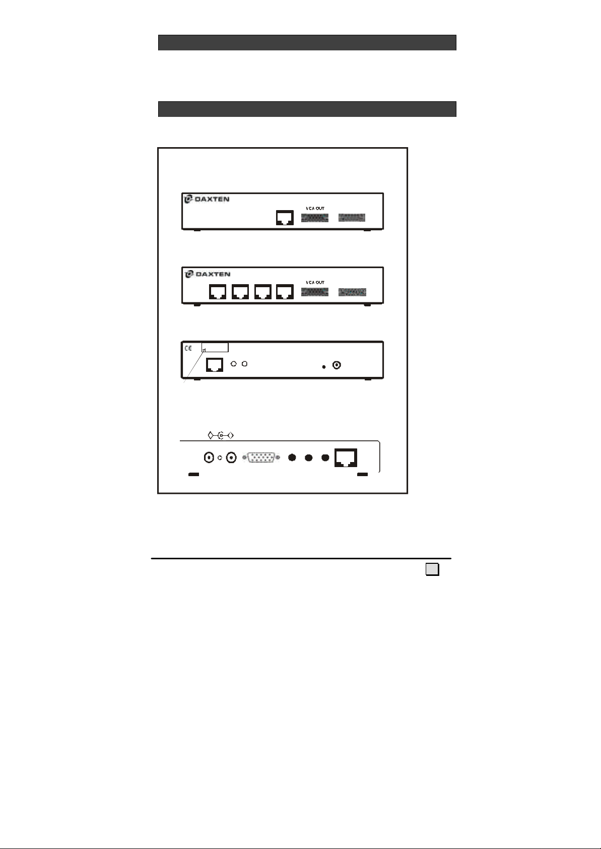
Rear view of Galaxy TX 1and Tx4
UTP IN
9-24 V DC
UTP in
Front view of Galaxy RX 60
GETTING STARTED
This manual describes the Galaxy installation and operation of the Galaxy system.
CONNECTORS ON GALAXY
All versions of the models are listed here
Front view of Galaxy Tx1
Galaxy Tx1
VGA IN
Front view of Galaxy Tx4
Galaxy Tx4
OUT 3 OUT 2OUT 4
EQ GAIN
Distance label
DC
9-20V
- +
VGA out
R G B
Galaxy Rx60 DC jack connectors—There are two DC jack connectors on the
Rx60, both of which can accept power supplies giving between 9-20vdc. The second
jack connector is available for use in contexts where a TFT screen, for example, is
4
Page 7
powered by a 19vdc mains adapter. Since the Rx60 only uses 200ma, the TFT mains
Rx60
A i
n
VGA o
u
t
9-24 V D
C
adapter will normally be able to power the Rx60 as well. This is done by plugging the
DC jack from the TFT mains adapter (possibly with the help of a DC jack adapter)
into one of the Rx60 DC jack connectors. A jack-jack cable, which must be obtained
from a stockist or constructed from components, can then be used to take the 19vdc
current from the Rx60 to the TFT screen. This obviates the necessity of a second
mains adapter for the Rx60.
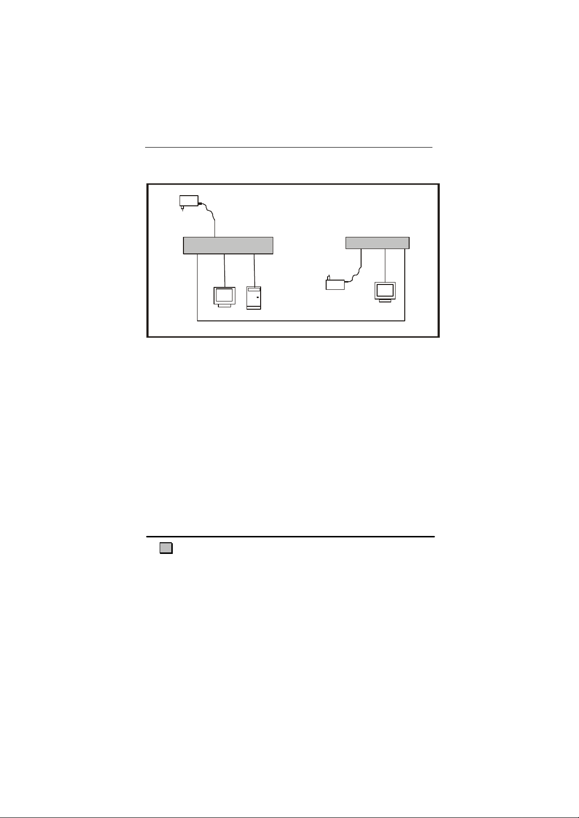
Applications
9- 24
V DC
Tx1
IN
UTP
V GA out
UTP OUT
V G
5
Page 8
Tx1 w/UTPin
V
GA
o
u
t
9-24
9-24 V D
C
Tx4 w/UTPin
Tx4 w/UTPin
Tx1 w/UTPin
Rx60
Rx60
V DC
Tx1
VGA in
VGA out
UTP OUT
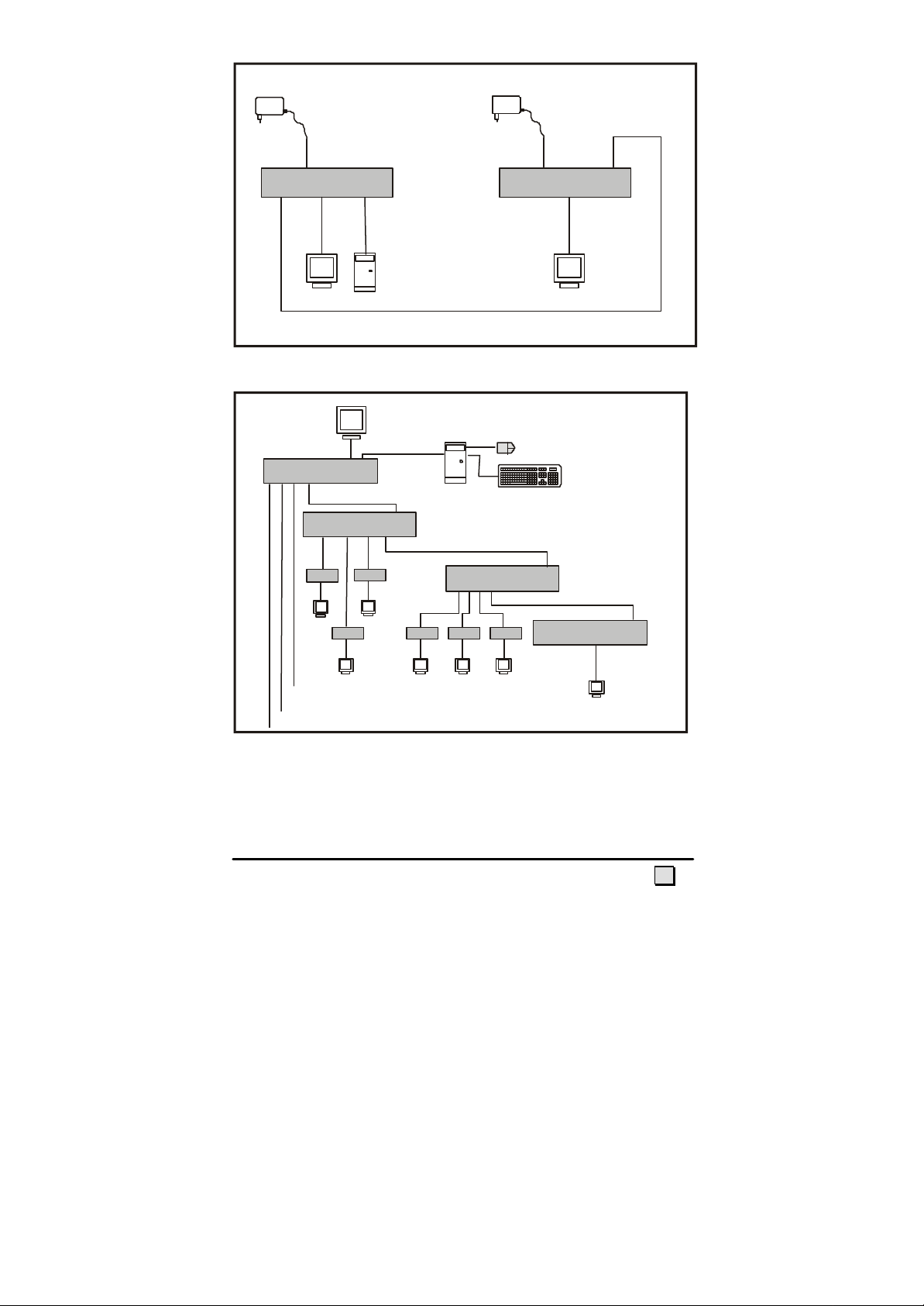
Figure 2: Galaxy Tx1 connected to one Galaxy TX1 with UTP In module
Tx4
IN
UTP
Rx60
Large-scale system
Rx60
Rx60
Rx60
6
Page 9
Voyager 125 Local
UTP
Monitor
UTP in
Tx1 w/UTPin
UTP
OUT
UTP
Voyager 125 Remote
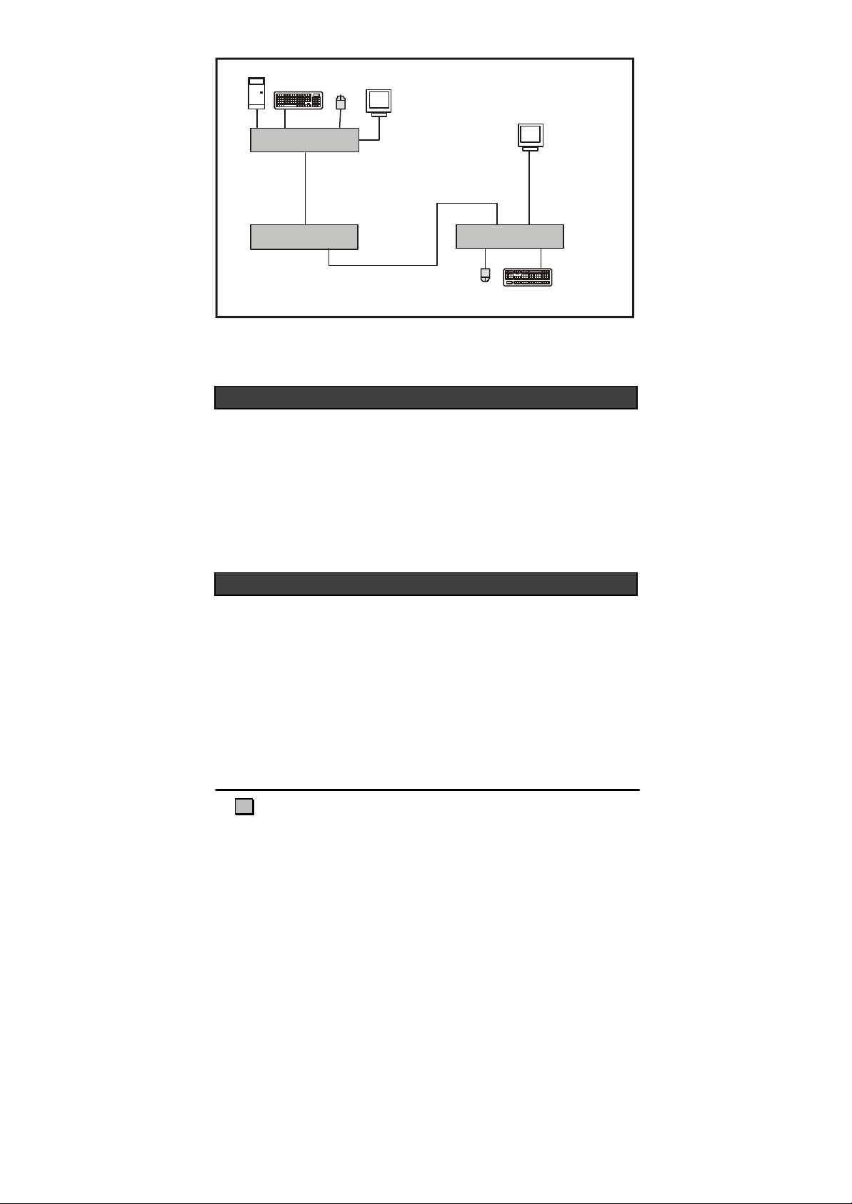
Galaxy Tx1 with UTPin module used as repeater for high resolution 1200 X 1600 over long
BEFORE INSTALLATION
distance in a Voyager 125 system
Galaxy Transmitter and Galaxy receivers.
When planning large installations please chose the right boxes and configuration.
When working with Daisy chains please make a drawing with cable lengths of your
system and give the boxes a numbers so it is possible to locate the boxes on the
drawing. Write down the configuration for the box if it contains a delayline so you
can put in a spare box with the right settings.
PROCEDURE FOR INSTALLATION
Begin installation from the info-computer.
Connect a Galaxy Tx1 or Tx4 (without UTP-in module) to the Info-PC.
Put on a still test image on the info-computer.
A) Connect a Rx60 receiver to the first Galaxy. Connect a monitor to the Rx60;
adjust the R G B for the best picture.
B) OR Connect a Tx1/4 RepeaterStation or a Rx125/300; adjust the EQ and
Gain for the best picture.
The Galaxy products are made in many versions for special requirements: With and
7
Page 10
without UTP in modules, with and without delay lines.
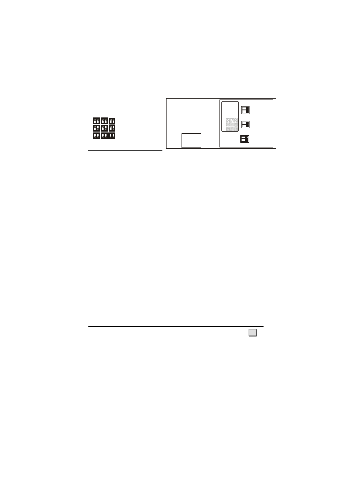
R G B 200-300 M 100-200 M 0-100 M
The UTP in modules differ in equalizing: the 125M module work with UTP lines up
to 125M. For longer distances use the 300M Version with UTP-in for distances
between 125 and 300 m
The 125M version has no inside distance switches.
The 300 version has inside switches for distance adjustment.
Galaxy Repeater station TX1/TX4 300M and Rx300
Please Notice! The distance of the cat5 cable is set by micro switches inside the
Galaxy Repeater 300M/Rx300.
R G B
200-300 M
100-200 M
0-100 M
8
Page 11

As default the distance is set to maximum 300 M. Changes in distance settings are
made inside the Tx Repeater/Rx300.
If the picture has visible vertical shadows it can be improved by adding internal or
external delay line.
To get the highest picture quality connect a monitor direct to the Tx units to
calibrate the EQ and Gain before moving on to the next repeater or receiver box.
After installation adjustments should only be carried out on the monitor settings and
Rx60/125/300 ends otherwise the pictures on the other boxes will change.
TROUBLE SHOOTING
Video
No picture on the Tx1.
1) Is the Green LED lit on the unit? No power, no transmission
2) Bad picture quality with very long transmission lines—Daxten can, on special
order deliver Cat 5E cable optimized for VGA transmission. Adding a delay
line (skew delay compensator) will also help.
3) Is this receiver fitted with an UTP-in card ? Add one.
4) Is the transmitter first unit working? Check local out.
5) Check the cables.
6) No picture will be showed if you use the VGA input on a Tx fitted with an
UTP-in Module.
7) Check the UTP cabling if you have problems with the colours.
8) If the picture shakes and contains noise you have to isolate the problem by
removing the UTP cables to some of the UTP units in order to find the line
and box with the problems. Check the ground. Call an electric technician with
grounding skills and test equipment for proper grounding.
9) The UTP Cabels are made the same way as used for networking
10) None of the cables for the Information system can be used to carry other
data or be connected to any networking equipment.
11) Noisy picture if ground problems occur over long distance. These problems
are solved by experiments with grounding the housings or adding ground loop
isolators. If the voltage potential is large enough, your equipment won’t be
able to handle the excess voltage and one of your ports will be damaged. You
can’t test for ground loops. You don’t know you have one until picture fails.
A ground loop is a current across a conductor, created by a difference in
potential between two grounded points, as in two buildings connected by a run
of data lines. When two devices are connected and their potentials are
different, voltage flows from high to low by travelling through the UTP
9
Page 12
cable.
SERVICE INFORMATION
How long distance is it possible to make one line?
The Tx1 and Tx4 has been tested with 900 meters without delaylines at 800x600.
To go long distance you need a delay-line compensator to restore the signal.
In information systems it is common to work in low resolution. Users are in distance
of the display and need larger types. Daylight makes it difficult to work with
monitors and displays outdoor. Using smaller displays needs larger types. Try reading
your information in two meters is it readable?
ADDING A DELAYLINE
If you are running long distance and high resolution pictures with small text you
might see that Black don’t turn into White. The texts on the monitor have small
shadows
Put on a test image on the central computer. The best test picture is made of red
green and blue lines above each other. If the 3 colour lines do not match on the
monitors you need delay-line compensating equipment.
The improvement can be made using an internal or external skew compensator.
The Tx1 and Tx4 repeaters can use an internal compensator type Galaxy-TXSK.
Maintenance and repair
The units do not contain any user-serviceable parts inside. Any malfunction of the
unit should be reported to a factory-authorised repair centre for service. Any
discrepancies in the operation of the unit according to this manual should be reported
to the Technical Support Department of Daxten.
Technical support
If you cannot determine the nature of a problem, please call Daxten and ask for
Technical Support.
If possible call from a phone located near the unit - we may be able to solve your
problem directly over the phone. If we cannot solve your problem, and the fault is
supposed to be in the unit, we will issue a Return Material Authorisation (RMA)
number that must appear on the outside of all returned products. The unit should be
10
Page 13

double-packed in the original container, insured, and shipped to the address given to
you by our Technical Support representative.
11
Page 14
APPENDIX A. GENERAL SPECIFICATIONS
Galaxy Tx1
Size 215 x 105 x 44 mm (8.46 x 4.13 x 1.73 in.)
Weight 0.80Kg (1.77lbs)
Power Consumption Max. 700mA with UTP-in module
Recommended Input Power Regulated DC 12V/1,3A or 9V/2A
Galaxy Tx4
Size 215 x 105 x 44 mm (8.46 x 4.13 x 1.73 in.)
Weight 0.80Kg (1.77lbs)
Power Consumption Max. 700 mA with UTP-in module
Recommended Input Power Regulated DC 12V/1,3A or 9V/2A
Galaxy Rx60
Size 160 x 65 x 28 mm (6.30 x 2.56 x 1.10 in.)
Weight 0.35 Kg (0.77lbs)
Power Consumption Max. 120 mA
Recommended Input Power Regulated DC 12V/1,3A or 9V/2A
Please note that these specifications are subject to change without prior notice.
12
Page 15

Unit 5 Distribution Centre
Shannon Free Zone
Shannon, Co. Clare
Ireland
www.daxten.ie
Tel: +353 (0) 61 23 4000
Fax: +353 (0) 61 23 4099
•
Künstlergasse 11/4
A-1150 Wien
Österreich
www.daxten.at
Tel: +43 (0)1 879 77 65
Fax: +43 (0)1 879 77 65 30
•
C/Florian Rey, 8
50002 Zaragoza
España
www.daxten.com.es
Tel: +34 902 197 662
Fax: +34 976 201 633
•
www.daxten.com
1579 Lexington Road
Green Oaks, IL 60048
Tel: +1 847 816 1337
Fax: +1 847 816 4558
USA
www.daxten.us
•
Salzufer 16, Geb. B
10587 Berlin
Deutschland
www.daxten.de
Tel: +49 (0) 30 8595 37-0
Fax: +49 (0) 30 8595 37-99
•
B.P 04 - 77
Route de Cheptainville
91630 Marolles en Hurepoix
France
www.daxten.fr
Tel: +33 (0)1 64 56 09 33
Fax: +33 (0)1 69 14 88 34
•
4 Harp Business Centre
Apsley Way
London NW2 7LW
United Kingdom
www.daxten.co.uk
Tel: +44 (0) 20 8438 3800
Fax: +44 (0) 20 8438 3899
•
Seebahnstr. 231
8004 Zürich
Schweiz
www.daxten.ch
Tel: +41 (0) 43 243 32 11
Fax: +41 (0) 43 243 32 16
•
Udviklingsparken
Sønderhøj 46
8260 Viby J
Denmark
www.daxten.dk
Tel: +45 8734 5610
Fax: +45 8734 5611
•
 Loading...