

Page 1

Installer/User Guide
LongView
®
1000
Page 2

Page 3

LongView® 1000
Installer/User Guide
Avocent, the Avocent logo, The Power of Being There and LongView are
registered trademarks of Avocent Corporation or its affiliates. All other
marks are the property of their res pective owners.
© 2005 Avocent Corporation. All rights reserved. 590-550-501B
Page 4

USA Notification
W arning: Changes or modifications to this unit not expressly approved by the party responsible for compliance
could void the user’s authority to operate the equipment.
Note: This equipment has been tested and found to comply with the limits for a Class A digital device,
pursuant to Part 15 of the FCC Rules. These lim its are designed to provide reasonable pro tection against
harmful interference when the equipment is operated in a commercial environment. This equipment generates,
uses and can radiate radio frequency energy and, if not installed and used in accordance with the instruct i on
manual, may cause harmful interference to radio communications. Operation of this equipment is a residential
area is likely to cause harmful interference, in whi ch case the user will be req uired to correct the inte rference at
his/her own expense.
Canadian Notification
This digital apparatus do es not exceed Cla ss A limits for radio n oise emissions from digital ap paratus set out i n
the Radio Interference Regulations of the Canadian Department of Communications.
Le présent appareil numérique n’émet pas de bruits radioélectriques dépassant les limites applicables aux
appareils numériques de la classe A prescrites dans le Réglement su le brouillage radioélectrique édicté par le
Minstére des Co mmunications du Canada.
Japanese Approvals
Safety and EMC Standards
EN55022 Class A, EN 55024, EN 61000-3-2, EN 61000-3-3, EN60950, FCC 47C FR Part15 Class A, CSA
C22.2 No. 60950, IEC 60950, FCC 15 Class A, UL 60950 third edition, VCCI Class A
Page 5

TABLE OF CONTENTS
Chapter 1: Product Overview.............. ...... ....... ...... ....... ...................................... ....... ..... 1
Features and Benefits ........................................................................................................................1
Compatibility with Peripherals..........................................................................................................1
Safety Precautions .............................................................................................................................2
Chapter 2: Installation ..... ....... ...... ....................................... ...... ....... ...... ....... ...... ....... ..... 3
Getting Started.......................................... ...... ...... .............................................................................3
Mounting options........................................................................................................................3
Connecting the local keyboard, monitor and mouse ..................................................................3
Connecting power.......................................................................................................................6
Chapter 3: Operations ..... ....... ...... ....................................... ...... ....... ...... ....... ...... ....... ..... 7
About Your LongView 1000 Extender ...............................................................................................7
Configuring keyboard layout and emulation for the receiver
via the OSD.................................................................................................. ...... ...... ..........................8
Configuring keyboard layout and emulation for the transmitter
via the OSD.................................................................................................. ...... ...... ..........................8
Configuring your OSD hotkey sequence.....................................................................................9
Activating OSD Timeout.............................................................................................................9
Displaying system information...................................................................................................9
Upgrading Your LongView 1000R Receiver and Transmitter
via Bootloader................................ ...... ..... .......................................................................................11
Activating bootloader...............................................................................................................12
Bootloader features .............................................................................. ...... ...... ........................13
iii
Appendices..................................................................................................................... 19
Appendix A: Technical Specifications......................................................................................19
Appendix B: Technical Support ................................................................................................21
Appendix C: Troubleshooting...................................................................................................22
Page 6

iv LongView 1000 Installer/User Guide
Page 7

CHAPTER
Product Overview
1
Features and Benefits
The Avocent LongView® 1000 extender, which utilizes the LongView 1000R receiver and an
AMIQDM module (transmitter), allows PS/2 and USB keyboard, video and mouse (KVM)
peripherals to work seamlessly from up to 1000 feet away from your server. Standard UTP cabling
makes installation simple and keeps costs low. The LongView 1000R receiver can be rack
mounted, desk mounted or mounted on the back of your monitor.
1
Its industry-stan dard desi gn makes t he LongVie w 1000 ex tender compat ible w ith virtual ly any P C,
display technology and operating system. Installation requires no new drivers or software.
Figure 1.1: LongView 1000R Receiver
Compatibility with Peri phe rals
The LongView 1000 extender is compatible with the following peripherals:
• Keyboard - The LongV iew transmitter and receiver support standard PS/2 and USB keyboards.
• Mouse - The LongView transmitter and receiver support 2-button PS/2 and USB mice. Mice
that have more than two buttons work with the reduced functionality of a 2-button mouse.
• V ideo - The LongView 1000 extender supports VGA, SVGA, XGA and UXGA resolutions up
to 75
Hz refresh rate. Both CRT and LCD monitors with standard 15-pin high density
connectors are
supported.
Page 8

2 LongView 1000 Installer/User Guide
• Audio - Speakers are supported on the receiver side of your LongView 1000 extender,
provided the transmitter has been connected to the sound card of your PC with the provided
audio cable.
Safety Precautions
To avoid p ot ential video and/or keyboard problems when using Avoc ent products:
• If the building has 3-phase AC power, ensure that the server and monitor are on the same
phase. For best results, they should be on the same circuit.
To avoid potentially fatal shock hazard and possible damage to equipment, please observe the
following precautions:
• Do not use a 2-wire extension cord in any Avocent product configuration.
• Test AC outlets at the server and monitor for proper polarity and grounding.
• Use only with grounded outlets at both the server and monitor. When using a backup
Uniterruptible Power Supply (UPS), power the server and the LongView transmitter off the
same supply.
NOTE: The AC inlet is the main disconnect.
Page 9

CHAPTER
Installation
2
Getting St arted
Before installing your LongView 1000 extender system, refer to the list below to ensure that you
have all the items necessary for installation.
Needed for the LongView 100 0 ext e n de r system
• LongView 1000R receiver (supplied)
• System specific AMIQDM module (sales option dependent, contact Avocent)
• External Power Supply (supplied)
• IEC power cord (supplied)
• LongView 1000 Quick Installation Guide (supplied)
3
Mounting options
The LongView 1000R receiver features the following mounting options, allowing you to easily
adapt to most work environments:
• Under desk mounting via the horizontal mounting bracket
• Monitor mounting via the mounting plate accessory
• Rack mounting via the rack mount kit
NOTE: Mounting accessories are ordered separately. Contact Avocent for more information.
Connecting the local keyboard, monitor and mouse
The following instructions will enable you to connect your LongView 1000 extender system.
WARNING: To reduce the risk of electric shock or damage to your equipment -
Disconnect the power from the extender by unplugging the power supply from the electrical outlet.
Page 10
4 LongView 1000 Installer/User Guide
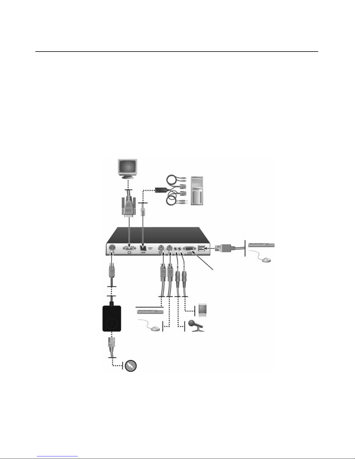
To connect the LongView 1000R receiver:
1. Select a convenient location for your LongView 1000R receiver.
2. Plug your keyboard, monitor and mouse cables into the appropriate ports on the back of
the LongView 1000R receiver.
3. Insert one end of a UTP cable into the LINK port on the rear of the LongView 1000R receiver.
4. Route the UTP cable to the AMIQDM module at the remote server, up to 1000 feet (300
meters) away and connect them together.
AMIQDM Module
LongView 1000R Receiver
USB Port
Serial Port
External
Power
Supply
Local Peripher a ls
Figure 2.1: LongView 1000R Receiver and AMIQDM Module Installation
Page 11
Chapter 2: Installation 5
K
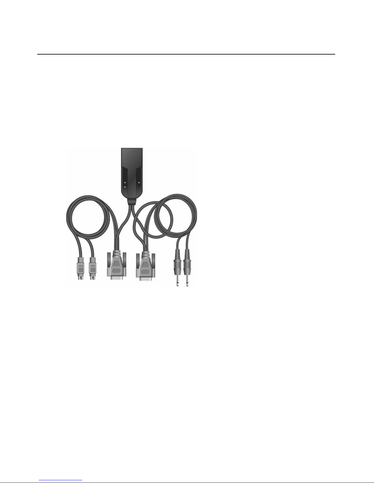
To connect the AMIQDM module:
1. Power down the remote se rver.
2. Connect the AMIQDM module keyboard, monitor and mouse connectors to the appropriate
ports on the back of the server.
3. Connect the AMIQDM module s erial and audio co nnectors int o the appropr iately labe led ports
on the back of the server, if desired.
4. Power up the server.
eyboard, Mouse
Figure 2.2: PS/2 AMIQDM Module
Video
Serial
Mic
Audio
Page 12

6 LongView 1000 Installer/User Guide
Connecting power
The LongView 1000R receive r f eatures an ex ter nal power supp ly with a 4-pin miniDIN connector.
A DC port is located on the rear of the LongView 1000R receiver.
NOTE: Use only an Avocent-supplied power supply.
To connect power to the LongView 1000R receiver:
1. Plug the external power supply’s 4-pin miniDIN connector into the DC port on the
LongView 1000R receiver.
2. Connect the detachable IEC power cord into the power supply.
3. Plug the IEC power cord into an appropriate wall outlet.
Page 13

CHAPTER
Operations
3
About Your LongView 1000 Extender
While the default s etti ngs on your LongVi ew 1000 ex tender wil l work with mo st s ystems, you may
choose to change settings to better fit your extender system. Internal settings such as keyboard
layout, emulation and hotkey sequ ences can be configured via the On-Screen Display (OSD), while
Flash upgrades are available via the bootloader function. The OSD also displays your system
settings and information about your connected transm itter .
NOTE: Table 3.1 lists available hotkey options to access the OSD.
7
Figure 3.1: Configuration Screen
Page 14

8 LongView 1000 Installer/User Guide
Configuring keyboard layout and emulation for the receiver
via the OSD
To change your keyboard layout and/or emulation:
1. Activate the OSD by pressing the hotkey sequence. If you are activatin g the OSD f or the
first time, any of the sequences in Table 3.1 will activate the display. Ensure the Config tab
is selected.
Tab le 3.1: OSD Hotkey Sequences
Hotkey Sequences (all sequences are default until selected)
Print Screen Alt - Alt (L)
Ctrl - Ctrl ( L - R) Alt - Alt (R)
Ctrl - Ctrl ( L) Shift - Shift (L - R)
Ctrl - Ctrl ( R) Shift - Shift (L)
Alt - Alt (L - R) Shift - Shift (R)
Scroll - Scroll
2. Click th e Local radio button to change keyboard settings for the LongView 1000R receiver.
3. Use the Layout drop-down menu to scroll to and select your desired country.
4. Select the type of keyboard you are using from the Emulation drop-down menu. The LongView 1000R receiver supports standard, Chyron Duet and Pinnacle FAK keyboard emulation.
5. Click Apply to save settings, or click Close to exit without saving changes.
Configuring keyboard layout and emulation for the transmitter
via the OSD
To change your keyboard layout and/or emulation:
1. Activate the OSD by pressing the hotkey sequence. Ensure the Config tab is selected.
2. Click th e Remote radio button to change settings for the remote transmitter.
3. Use the Layout drop-down menu to scroll to and select your desired country.
The PS/2 AMIQDM supports standard and Pinnacle FAK. The Emulation drop-down menu is
greyed out if a USB or Sun AMIQDM is attached to the receiver and the Remote radio button
is selected.
Page 15

Configuring your OSD hotkey sequence
To change the hotkey sequence that activates your OSD:
1. Activate the OSD by pressing the default or your currently configured hotkey sequence.
Ensure the Config tab is selected.
2. Select your desired hotkey sequence from the OSD Hotkey drop-down menu.
The following table lists selectable hotkey sequences available to activate the OSD.
Activating OSD Timeout
The LongView 1000R receiver can be configured to log out users after 15 minutes of inactivity.
To activate OSD Timeout:
1. Activate the OSD by pressing the hotkey sequence. Ensure the Config tab is selected.
2. Click th e OSD Timeout checkbox at the bottom-left corner of the screen.
Displaying system information
Chapter 3: Operations 9
To display system information:
1. Activate the OSD by pressing the hotkey sequence.
2. Click on t he Info tab.
3. Click th e Local radio button for information about the LongView 1000R receiver; click the
Remote radio button for information about the transmitter.
NOTE: The distance between the LongView 1000R receiver and remote transmitter is shown at the bottom of
the screen.
Page 16

10 LongView 1000 Installer/User Guide
Figure 3.2: Local System Information
Figure 3.3: Remote System Information
Page 17

Figure 3.4: No Device Connected
Chapter 3: Operations 11
Upgrading Your LongView 1000R Receiver and Transmitter
via Bootloader
The LongView 1000 extender system can be upgraded through the serial port. All terminal
commands are accessed through a terminal or PC running HyperTerminal
or equivalent.
To access the Terminal Applications menu:
Connect a terminal or PC running terminal emulation software to the serial port on the back panel
of the LongView 1000R receiver using a null modem cable. The terminal should be set to 57600
baud, 8 data bits, no parity, 1 stop bit and no flow control .
®
emulation software
Page 18

12 LongView 1000 Installer/User Guide
Figure 3.5: Com1 Properties
Activating bootloader
To activate bootloader:
1. Activate the OSD by pressing the hotkey sequence. Ensure the Config tab is selected.
2. Click th e Invoke checkbox in the bottom-right corner of the screen.
3. Click th e Call button.
The screen closes and the LongView 1000R receiver bootloader OSD is displ ayed. The term inal
menu is now available on the serial port.
Page 19

Figure 3.6: Bootloader Menu: No Connected Device
Chapter 3: Operations 13
Figure 3.7: Active Bootloader Menu
Bootloader features
You can select several bootloader options using the terminal menu keyboard.
Resetting the LongView 1000R receiver from the terminal menu
Once bootloader is active, you can exit the menu and reset the device by typing 0.
Page 20

14 LongView 1000 Installer/User Guide
LongView 1000R receiver upgrade via XMODEM
Option 1 allows you to program th e bootloader or the ap plication of the LongView 100 0R receiver.
The update file has to be sent via XMODEM from the terminal software after this option is chosen.
The LongView 1000R receiver will verify that the transferred file is valid for the device after it has
received the first six XMODEM blocks. If a wrong file is sent, the update is cancelled. During the
transfer, the terminal will provide a progress displa y. After the tran sfer, the f l ashed data is check ed
and the device reboots.
The LongView 1000R receiver may need both application and boot code updated. The update
release notes will specify whether one or both files are needed. Always update the boot code
followed by the application.
Figure 3.8: Boot or Application Upgrade of the LongView 1000R Receiver
NOTE: You can also visit www.avocent.com to access upgrade files.
Page 21

Figure 3.9: OSD During XMODEM Up date
Chapter 3: Operations 15
NOTE: Figure 3.9 will display during an XMODEM update via the serial console of the LongView 1000R receiver.
The boot and application codes must be updated separately using the XMODEM. The percentage complete
shows the amount for the file being transferred.
T ransmitter boot and application upgrade via XMODEM
Option 2 allows you to program the boot and application of the connected transmitter. The update
file has to be sent via XMODEM from the terminal software after this option is chosen.
Figure 3.10: Upgrade Transmitter Boot or Application Code
Page 22

16 LongView 1000 Installer/User Guide
The OSD screen in Figure 3.11 will appear when a connected transmitter is being updated. Up to
three files (boot, application and/or FPGA) can be sent to the transmitter. The update release notes
will say which files are needed. Always update the boot code before the application. The
percentage bar displays the percentage complete for a particular file.
Figure 3.11: Updating a Local Transmitter
T ransmitter FPGA upgrade via XMODEM
Option 3 allows you to program the FPGA code of the connected transmitter. The update file has to
be sent via XMODEM from the terminal software after this option is chosen. See Figure 3.12.
Figure 3.12: Upgrade Transmitter FPGA
Page 23

Displaying information about connected devices
Type ? to display the System Information of the connected transmitter.
Chapter 3: Operations 17
Figure 3.13: Transmitter Information Screen
Page 24

18 LongView 1000 Installer/User Guide
Page 25

APPENDICES
Appendices
Appendix A: Technical Specifications
Table A.1: Long View 1000 Extender Product Specifications
Extension Por ts
19
Number
Connectors
User Ports
Number
Type
Connectors
Dimensions
H x W x D 27 x 210 x 188 mm (1.06 x 8.27 x 7.40 in)
Weight
Heat Dissipation
Power Consumption
AC-input power
AC-input current rating
AC-frequency
1
RJ-45 switch interconnect
PS/2: 1; USB : 1 (with two conn ec tors); Serial: 1; VGA video: 1
PS/2, USB a nd VGA video
6-pin mini DIN, PS/2 keybo ard and mouse; USB Type A, USB keyboard and
mouse;15HDD female: VGA; 9-pin D-Shell, Serial; 3.5mm audio jacks, line out and mic
1Kg (2.20 lb) without packaging, cables, power supply and literature
90 K
25 W
25 W maximum
A
50/60 Hz
Temperature
Humidity
Supported Hardware
Peripherals
Video Resolution
0° to 40° Celsius (32° to 104° Farenheit) operating
-20° to 50° Celsius (-4° to 122° Farenheit) nonoperating
0 to 95% noncondensing operating
PS/2 keyboard and mouse, USB keyboard and m ouse, speakers, microphone, serial
devices (ma x baud rate of 38 ,400 baud)
1280 x 1024 w i t h 1000 feet of UTP from serv er to user; 1600 x 1200 with 100 feet of
UTP from server to user
Page 26

20 LongView 1000 Installer/User Guide
Table A.1: Long View 1000 Extender Product Specifications (Co ntinue d)
Supported Hardware
Sync Types
Safety and
EMC Standards
Separate horizontal and vertical; sync on green (as used on SGI
and HP9000); composite
EN55022 Class A, EN55024, EN 61000-3-2, EN 61000-3-3, EN60950, FCC 47CFR
Part15 Class A, CSA C22.2 No. 60950, IEC 60950, FCC 15 Class A, UL 60950 third
edition, VCCI Class A
Page 27

Appendix B: Technical Support
Our Technical Support staff is ready to assist you with any installation or operating issues you
encounter with your Avocent product. If an issue should develop, follow the steps below for the
fastest possible service.
To resolve an issue:
1. Check the pertinent section of this manual to see if the issue can be resolved by following the
procedures outlined.
2. Check our web site at www.avo cent.com /sup por t to search the knowledge base or use the online service request.
3. Call the Avocent Technical Support location nearest you.
Appendices 21
Page 28

22 LongView 1000 Installer/User Guide
Appendix C: Troubleshooting
Table C.1: Troubleshooting the LongView 1000R Receiver
No power status light on LongView 1000R receiver
Verify that the power supply is plugged in correctly.
Ensure that the power cable from the Avocent-supplied power supply is securely
plugged into the LongView 1000R receiver.
No video on monitor attached to LongView 1000R receiver
Verify that the monitor attached to the LongView 1000R receiver has power.
Ensure that the video cable from the monitor is securely plugged in to the correct
connector on the LongView 1000R receiver.
Ensure that the video cable from the AMIQDM module is securely plugged in to
the correct connector on the server.
Verify that the server is powered.
Cycle power to the LongView 1000R receiver. An informational message should
appear on the monitor for a brief moment. If the message does not appear, check
the monitor by plugging the video cable from the monitor directly into the server to
verify that the monitor is working and that the server is generating active video. If
this is functioning, check that the display settings for your server are set no higher
than a resolution of 1024 x 768 at 60 Hz refresh rate. If the monitor does not
function correctly, replace it.
As a last check, plug the video cable from the monitor directly into the server to
verify that the monitor is working and that the server is generating active video. If
this is functioning, check that the display settings for your server are set no higher
than a resolution of 1024 x 768 at 60 Hz refresh rate. If the monitor does not
function correctly, replace it.
No mouse or keyboard operation from peripherals attached to LongView 1000R receiver
Ensure that the mouse and keyboard operation cables are connected to the
correct PS/2 or USB ports on the LongView 1000R receiver. Match the connector
color codes (green is mouse and purple is keyboard).
Ensure that the mouse and keyboard cables from the AMIQDM module are
connected to the correct PS/2 or USB ports on the server. Match the connector
color codes (green is mouse and purple is keyboard).
Retest the mouse and keyboard by connecting them directly to the server and
rebooting. If one does not function correctly, replace the nonfunctioning peripheral.
Page 29

Table C.1: Troubleshooting the LongView 1000R Receiver (Continued)
No audio from speakers attached to LongView 1000R receiver
Ensure that the audio cable is securely plugged into the line out port of the server
(should be color-coded green).
Ensure that the speaker cable is securely plugged into the line out port of the
LongView 1000R receiver.
Retest the speakers by connecting them directly to the server. If they do not
function correctly, replace them.
Ensure speakers are powered.
Poor video quality on monitor attached to LongView 1000R receiver
Ensure that the video cable from the monitor is securely plugged in to the correct
connector on the LongView 1000R receiver.
Ensure that the video cable from the AMIQDM module is securely plugged in to
the correct connector on the server.
Appendices 23
Page 30

24 LongView 1000 Installer/User Guide
Page 31

Page 32

 Loading...