

Page 1
S
OLAR POWER
K
IT
FOR W
This manual describes how to install the Solar Power Kit for Wireless Weather
Stations. The power kit enables wireless stations to be stand-alone units that
combine transmitter and renewable power source in one weather-resistant
shelter, thereby eliminating the need to run a cable to a power outlet or to
replace batteries regularly.
This kit is designed for three applications: one, transforming an ordinary
Wireless Weather Station into a solar-powered station; two, transforming an
EZ-Mount Weather Station into a solar-powered and wireless station; and
three, transforming a standard Monitor or Wizard station into a solar-powered
and wireless station. For these last two applications, the SensorLink™ Transmitter and Receiver (#7610 and #7611) must be purchased separately.
CAUTION:
C
OMPONENTS
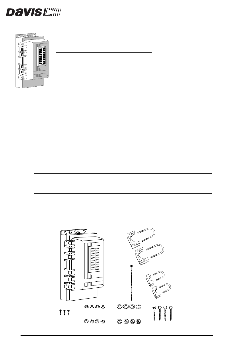
The Solar Power Kit includes the following components. Please be sure you
have all listed components before beginning.
Please note that while we have made every attempt to design and manufacture a safe product,
Davis Instruments cannot assume liability for any injury or damage caused directly or indirectly by the
installation or use of this product.
IRELESS WEATHER STATIONS
#6 x 1/2" (12.5 mm)
Screws
1/4" Flat Washers
1/4" Hex Nuts
Shelter
5/16" Flat Washers
5/16" Hex Nuts
Cable
Tie
2 1/4" U-Bolts
and Saddles
1 1/2" U-Bolts
and Saddles
1/4" Lag Screws
Product # 7709
Page 2

OOLS AND MATERIALS NEEDED
T
You may need the following tools and materials for this installation:
✦
Adjustable Wrench or 5/16” Wrench
Medium Flat Head Screwdriver
✦
✦
Medium Phillips Screwdriver
✦
Electrical Tape, Cable Clips and /or Cable Ties
Compass or Local Area Map
✦
L
OCATION
T
IPS
The following tips should help you find the best possible location and position
for your Solar Power Kit. If necessary, reposition your station to permit the
solar panel sufficient access to the sun’s rays.
The solar panel works best when the surface of the panel receives full sunlight.
✦
Mount the panel away from fences, buildings, trees or other obstructions
that may cast shadows over the panel.
The panel should be mounted facing south in the Northern Hemisphere and north
✦
in the Southern Hemisphere for maximum sun exposure.
NSTALLING
I
There are three procedures for installing the solar power kit, depending on
your current installation:
Page 2 Solar Power Kit
THE
S
OLAR
For standard (i.e., non-wireless, non-EZ) installations
✦
Use the solar power kit shelter to protect the transmitter from the elements. To transform a standard station into a solar-powered wireless
station, see “Installation for Standard Stations” on page 3.
For EZ-Mount installations
✦
Replace the EZ-Mount’s field case door with the power kit door and then
install the transmitter. See “Installation for EZ-Mount and Wireless Stations” on page 5 for details.
For Wireless installations
✦
Simply replace your current field case door with the power kit door. See
“Installation for EZ-Mount and Wireless Stations” on page 5.
P
OWER
K
IT
Page 3
NSTALLATION
I
FOR
TANDARD
S
TATIONS
S
To transform a standard station, follow these steps:
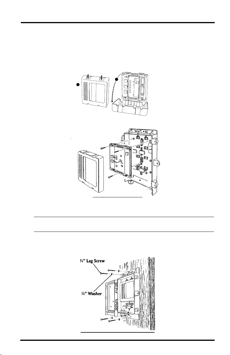
1. Open the shelter door using a flat head screwdriver.
2. Remove the cover from the transmitter by pushing down on the tabs at the top until
you can remove the tabs from the slots.
A
B
Base
Cover
3. Install the transmitter using the three #6 x 1/2” (12.5 mm) screws, as shown below.
#6 x 1/2" (12.5 mm)
Screws
I
NSTALLING
THE
T
RANSMITTER
4. Mount the shelter against a wall or post, on a small pipe, or on a large pipe.
CAUTION: Remember to face the solar panel south in the Northern Hemisphere (or north in the
Southern Hemisphere) for maximum sun exposure.
Wall or Post
✦
Attach the shelter to the mounting surface in the desired location using
the lag screws and 1/4" flat washers as shown below.
M
Installation for Standard Stations Page 3
OUNTING
P
OWER
K
W
IT
ON
A
ALL
P
OR
OST
Page 4

✦
Small Pipe - 3/4” to 1 1/4” (19 to 31 µm)
Use the 1-1/2" U-Bolts and saddles, and the 1/4" washers and hex nuts
as shown below.
OUNTING
M
✦
Large Pipe - 1 1/2” to 2 3/8” (38 to 60 mm)
P
OWER
IT
ON
A
MALL
K
IPE
S
P
Use the 2-1/4" U-Bolts and saddles, and the 5/16" washers and hex nuts
as shown below.
M
OUNTING
P
OWER
K
L
IT
ON
P
A
ARGE
IPE
5. Remove and label the cables from your existing junction box and insert them into the
appropriate jacks in the transmitter.
Refer to the SensorLink manual for instructions and illustrations.
6. Secure any exposed cables with electrical tape, cable clips and/or cable ties so they do
not whip about in the wind.
7. Continue with the transmitter and receiver installation using your SensorLink manual.
Page 4 Solar Power Kit
Page 5

NSTALLATION
I
To transform an EZ-Mount or Wireless station, follow these steps:
1. Unscrew and open the doors on your station field case and solar power kit shelter
with a flat head screwdriver.
2. Remove both doors by slipping them free of their hinges, as shown below.
Angle the door at about a 45 degree angle as shown. Then press firmly and
evenly to push the hinge pins from their cradles. Note: You may have to use
quite a bit of pressure.
3. Attach the solar power kit door to the field case, as shown below.
Again, positioning the door at a 45 degree angle from the base, squeeze the
door’s cradles around the base’s pins by pressing in hard with your thumbs
and holding the base still with your fingers.
FOR
EZ-M
OUNT
AND
W
IRELESS
TATIONS
S
4. If the transmitter is not yet installed, see steps 2-4 on page 3 to install the transmit-
ter in the field case. Once the transmitter is installed, refer to “Powering the Transmitter” on page 6.
Installation for EZ-Mount and Wireless Stations Page 5
Page 6

OWERING
P
1. Remove all power from the transmitter (i.e., AC and battery).
2. Run the power cord from the gel cell battery to the transmitter as shown below.
3. Refer to your Wireless Weather Station or SensorLink installation manual to complete
THE
the installation and test your reception.
RANSMITTER
T
Gel Cell Battery
* Rechargeable
Power
Plug
SensorLink
Transmitter
Page 6 Solar Power Kit
Page 7

NDERSTANDING
U
You may be interested to know something of how the kit operates. Aside from
the installation hardware, the kit consists of three key elements—solar panel,
battery, and regulator circuit:
Solar Panel
✦
Converts solar energy to electrical energy. The unit provided is rated at
0.5 Watts. It provides about 50 mA of current in bright sunshine
(1000 W/m2). In 2 hours it will provide enough power to operate an a
SensorLink transmitter for 10 days.
Note:
You can clean the solar panel with a water spray, or with a soft cloth and soapy water followed by a clean water rinse.
Battery
✦
The kit is designed to use the 1.2 Amp-Hour battery provided, but any
6-volt rechargeable battery may be used. The 1.2-Amp-Hour battery,
when fully charged, can supply power to operate a SensorLink
transmitter for 300 days without recharging, assuming an average
temperature of 68˚F (20˚C). It will run for about 250 days at 32˚F (0˚C)
and about 200 days at -4˚F (-20˚C).
CAUTION:
is capable of generating flammable gas. No spark, flame, or lighted cigarette should be allowed in
the vicinity.
✦
Regulator Circuit
In order to increase the efficiency and life of the battery, the circuit limits
the voltage to which the battery is charged, and it adjusts this voltage
according to the temperature at the rate of negative 7.5 mV per ˚C. This
ensures that the battery is fully charged for the conditions, but never
over-charged.
THE
S
OLAR
The battery is sealed, but it should be assumed that it (and any other rechargeable battery)
P
OWER
K
IT
Understanding the Solar Power Kit Page 7
Page 8

ROUBLESHOOTING
T
While the Solar Power Kit is designed to provide years of trouble-free operation, occasional problems may arise. If you experience a problem, please check
the troubleshooting tips below before calling technical support.
Solar panel fails to power station and battery is over 5 years old
✦
As the battery ages, it will lose capacity and may completely discharge. If
this is the case, simply replace the battery. (Do not incinerate the used battery; it may burst. Arrange for proper recycling in your locality.)
Solar panel fails to power station and battery is less than 5 years old
✦
If the solar kit fails to power the station, try the following:
Make sure the panel is not being shaded from the sun.
Open the solar panel shelter and check that the wire connections are secure
and that battery is free from corrosion and excessive deposits on the
terminal.
Clean the solar panel using a water spray, or a soft cloth and soapy water
followed by a clean water rinse.
Check the battery’s voltage with a voltmeter; the battery must have at least
5.5 V to power the station. (More than 6 V indicates an adequately-charged
battery.) Try exposing the kit (with console unplugged) to ample sunlight for
a week, or use a charger designed to recharge a 6 V gel cell battery.
If, after checking this troubleshooting guide, you are unable to solve the
problem, please call our technical support team at (510) 732-7814 for assistance
(M-F, 7 am–5:30 pm PST). Please do not return your unit for repair without
prior authorization.
Product Number: 7709
Davis Instruments Part Number: 7395-304
Solar Power Kit For Wireless Weather Stations
Rev. A Manual (1/18/99)
Controlled online: Weather Manuals/Accessories/Solar Power Kit for Wireless
This product complies with the essential protection requirements of the EC EMC Directive 89/336/EC.
© Davis Instruments Corp. 1999. All rights reserved.
SensorLink is a trademark of Davis Instruments Corp.
3465 Diablo Avenue, Hayward, CA 94545-2778
510-732-9229 • Fax: 510-732-9118
E-mail: info@davisnet.com • www.davisnet.com
 Loading...