

Page 1
S
OLAR
ND
A
6.5-A
The Solar Power Kit is designed to provide power to any Davis weather
station.
CAUTION: Davis Instruments assumes no liability for any injury or damage caused directly or indirectly by
the installation or use of this product.
P
OWER
MP
-H
OUR
K
ATTERY
B
IT
Product # 7708
Page 2

The solar power subsystem comprises three units:
✦
Solar Panel
Converts solar energy to electrical energy. The unit provided is rated at
10 Watts. It provides about 600 mA of current in bright sunshine
(1000 W/m
2
). In 1
∫ hours it provides power to operate the station for
more than 24 hours.
✦
Battery
A battery is not included in the kit. You may wish to provide your own.
The kit is designed to use the 6.5 Amp-hour Battery (7711), but any 12volt rechargeable battery may be used. The 6.5-Amp-Hour battery, when
fully charged, can supply power to operate the station for eight days
without recharging, assuming an average temperature of 68˚F (20˚C). It
will run for about seven days at 32˚F (0˚C) and about five days at -4˚F
(-20˚C).
✦
Regulator Circuit
The regulator circuit performs three functions, designed to increase the
efficiency and life of the battery:
Temperature-Compensated Voltage Limit
✦
The circuit limits the voltage to which the battery is charged, and it
adjusts this voltage according to the temperature at the rate of 28
mV per degree C. This ensures that the battery is fully charged for
the conditions, but never over-charged.
Load Disconnect
✦
The circuit disconnects the battery from the weather station if the
battery voltage drops below approximately 10.8 Volts. This ensures
that the battery is not deep-discharged, an event which shortens
battery life.
Re-Connect
✦
When the battery voltage has risen about 0.7 Volt above the disconnect voltage, the circuit re-connects it to the station. This ensures
that the battery is in the process of recharging before the load is
restored. The re-connect causes the station to reset and restart if the
standby battery was drained.
The regulator circuit also contains terminals (B3 and B4) to facilitate the
use of the Alarm Output Module in switching power to accessories (for
example a radio) to minimize power consumption.
CAUTION: The battery (#7711) is sealed, but it should be assumed that it (and any other rechargeable
battery) is capable of generating flammable gas. The battery should be located in a vented
space, if possible. No spark, flame, or lighted cigarette should be allowed in the vicinity.
Page 2 Solar Power Kit
Page 3
C
OMPONENTS
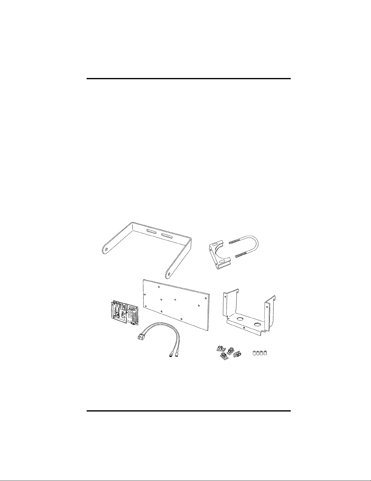
The Solar Power Kit includes the following components. Please make sure that
you have all the listed components before continuing.
✦
Solar Panel
✦
Solar Panel Bracket
2-1/4” U-Bolt
✦
✦
U-Bolt Saddle
✦
Regulator Circuit Assembly
Battery Cover Plate
✦
✦
Battery Mounting Bracket
✦
Battery Cable
Solar Panel Mounting Accessories
✦
Four End Caps
✦
✦
Four Rubber Sealing Tubes
Components Page 3
Page 4
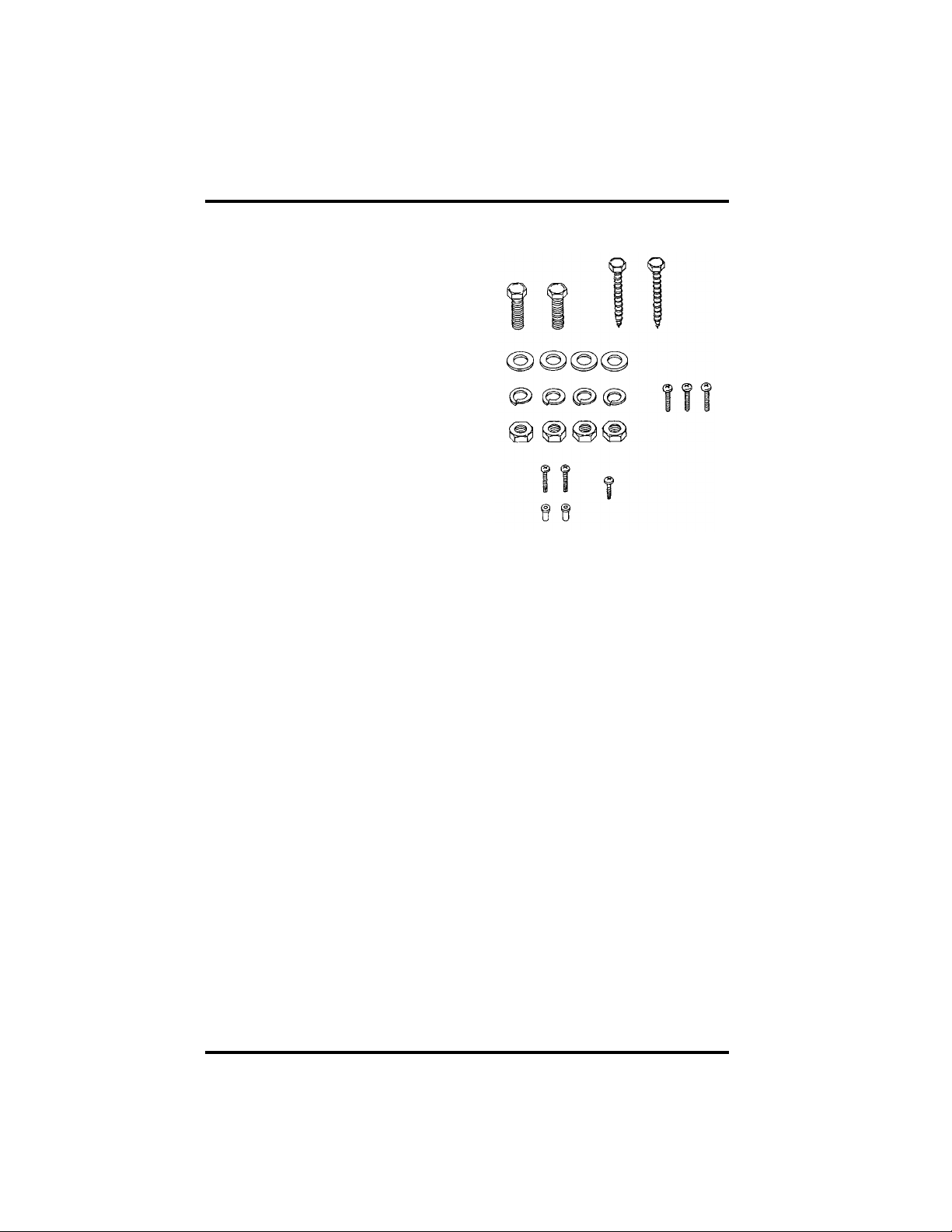
Installation Kit Hardware
✦
Two 5/16-18 x 3/4” (19
✦
mm) Machine Screws
✦
Two 1-1/2” (4 cm) Lag
Screws
✦
Four 5/16” Flat Washers
Four 5/16” Split Lock
✦
Washers
Four 5/16” Stainless Steel
✦
Hex Nuts
✦
Three #6-32 x 1/2” (12.5
mm) Machine Screws
Two #4-40 x 1/2” (12.5
✦
mm) Machine Screws
Two Nylon Screw
✦
Insulators
✦
One #6 x 1/2” (12.5 mm)
Sheet Metal Screw
T
OOLS
You may need some of the following tools and materials in order to install the
Solar Power Kit.
M
AND
✦
Battery
The kit is designed to use the 6.5-Amp-Hour Battery (Davis
Product #7711), but you may use any 12-volt rechargeable battery.
✦
Medium Phillips Screwdriver
Adjustable Wrench or 1/2” Wrench
✦
Protractor
✦
To adjust solar panel to the correct tilt angle.
✦
Magnetic Compass, Map of Local Area, or Watch
To align solar panel to south in the Northern Hemisphere (or north in
Southern Hemisphere). The watch may be used to set the panel facing
the sun at solar noon.
✦
Voltmeter
To check battery voltages.
ATERIALS
N
EEDED
FOR
I
NSTALLATION
Page 4 Solar Power Kit
Page 5

L
ABELING
Use the label sheets provided with your station to mark the battery cables
before you begin installation. Doing this now will help prevent confusion during the installation and if you ever need to disconnect the cables at a later date.
L
OCATION
The following tips should help you find the best possible location for your
solar panel:
Y
✦
Place one BATTERY/B2 label over both wires of the battery cable so the BATTERY
side of the label is nearest the end of the cable with individual slide connectors.
Place one BATTERY/B2 label onto the cable so the B2 side of the label is near the
plastic connector.
✦
Place the C1/CONSOLE PWR/P1 labels onto the power adapter cable, when
instructed to do so in “Connecting to the Regulator” on page 12.
Place the SOLAR PANEL/B1 label over both wires of the solar panel cable with B1
✦
near the connector.
T
✦
The solar panel works best when the surface of the panel receives full sunlight.
Mount the panel away from fences, buildings, trees or other obstructions that
may cast shadows over panel.
The panel should be mounted facing south in the Northern Hemisphere and north
✦
in the Southern Hemisphere.
✦
The optimum tilt angle for the panel (measured from the horizontal) is determined from the site latitude, and may be found from the table below.
OUR
IPS
C
ABLES
S
L
ITE
ATITUDE
0˚ to 4˚ 10˚
5˚ to 20˚ latitude + 5˚
21˚ to 45˚ latitude + 10˚
46˚ to 65˚ latitude + 15˚
65˚ to 75˚ 80˚
Labeling Your Cables Page 5
R
ECOMMENDED
T
A
ILT
NGLE
Page 6

I
NSTALLING
THE
B
ATTERY
The instructions below explain how to install the 6.5-Amp-Hour Battery (Davis
Product # 7711).
Installing the Battery in the Complete System Shelter
Follow the instructions below to mount the battery in the Complete System
Shelter (CSS). Note that if you have already mounted the console into the CSS,
you will need to remove it before installing the battery.
1. Slide the individual connectors from the battery cable onto to the battery terminals.
Be sure to connect the red wire to the positive (red) terminal and the black
wire to the negative (black) terminal.
A
TTACHING
B
ATTERY
C
ABLE
2. Secure the battery support bracket to the CSS using the #6 x 1/2” (15 mm) sheet
metal screw as shown below.
Begin by placing the hooks of the support bracket into the slots in the rear
panel of the CSS and pulling the bracket down to seat it.
3. Place the battery on the support bracket with the terminals towards the right.
P
B
LACING
ATTERY
INTO
C
OMPLETE
S
YSTEM
S
HELTER
Page 6 Solar Power Kit
Page 7

Installing the Battery in other shelters or locations
1. Connect the battery cable harness wires to the battery terminals (see illustration
“Attaching Battery Cable” on page 6.)
Be sure to connect the red wire to the positive (red) terminal and the black
wire to the negative (black) terminal.
2. Place the battery on a horizontal surface.
NSTALLING
I
THE
EGULATOR
R
IRCUIT
C
The instructions below explain how to install the regulator circuit in the Complete System Shelter (CSS).
1. Align the spacer posts at each corner of the regulator circuit over the holes in the bat-
tery cover plate.
Make sure to orient the regulator circuit so the words printed on the circuit
board are right side up.
2. Using firm but gentle pressure, push the charge circuit assembly down until the
spacer posts are firmly seated in the holes.
3. If you plan to mount the station console in the CSS, insert the #4-40 x 1/2” (15 mm)
screws into the nylon insulators and attach to the battery cover plate as shown below.
Do not use the self-tapping screws and nylon insulators supplied with the
CSS. The point on the self-tapping screws may inadvertently puncture the
battery. If the battery is installed in the CSS you must use the #4-40 x 1/2”
(15 mm) screws and nylon insulators supplied with the battery.
A
TTACHING
R
EGULATOR
C
IRCUIT
AND
C
ONSOLE
S
CREWS
B
C
TO
ATTERY
OVER
P
LATE
Installing the Regulator Circuit Page 7
Page 8

4. Attach the battery cover plate over the battery using the #6-32 x 1/2” (15 mm)
machine screw as shown below.
M
OUNTING
A
THE SOLAR PANEL
TTACHING
B
ATTERY
C
OVER
P
LATE
The solar panel may be mounted on the side of a wooden post or wall or on a pipe
with outside diameter between 2” and 2-1/2” (51mm and 64mm). The instructions
below take you through the procedure required to install the solar panel.
Mounting on a Wood Surface
1. Attach the mounting bracket to the surface using 1-1/2” (4 cm) lag screws as shown below.
Make sure that the solar panel will be facing south if mounting in the Northern Hemisphere or facing north if mounting in the Southern Hemisphere.
MOUNTING ON A WOOD SURFACE
Page 8 Solar Power Kit
Page 9

Mounting on a Pipe
1. Hold the mounting bracket and U-bolt saddle against the pipe and slide the ends of
the U-bolt through the holes in the saddle and the back of the mounting bracket so
that the U-bolts wrap around the pipe.
2. Secure the mounting bracket to the pipe using a 5/16” flat washer, a 5/16” split lock
washer and a 5/16” hex nut on each end of the U-bolt.
Make sure that the solar panel will be facing south if mounting in the Northern Hemisphere or facing north if mounting in the Southern Hemisphere.
MOUNTING ON A PIPE
Mounting the Solar Panel Page 9
Page 10

Attaching the Solar Panel to the Mounting Bracket
The solar panel is designed to pivot on the 5/16” screws.
1. Loosely attach the 5/16-18 x 3333////4444” (2 cm) screws, two 5/16” flat washers, two 5/16” split
lock washers, and two 5/16” stainless steel hex nuts to the mounting bracket as shown
below.
Do not tighten completely.
2. Slide the heads of the 5/16-18 x 3333////4444” (2 cm) screws into the channel on the sides of the
panel as shown below.
Slide the screw heads up the channel until they are at the middle of the
panel.
ATTACHING MOUNTING BRACKET TO PANEL
Page 10 Solar Power Kit
Page 11

3. Place a rubber tube into each end cap and insert end caps into the solar panel frame.
The tubes should just sit within the end cap. Do not force them all the way
into the end cap.
INSERTING TUBES AND END CAPS
4. Find the optimum tilt angle for the panel using the table in “Location Tips” on page 5.
5. Using a protractor, adjust the tilt angle of the panel until the angle the panel makes
with the horizontal matches the optimal tilt angle.
TILT ANGLE
6. Tighten the hex screws on the mounting bracket until the solar panel is securely held
at this angle.
Mounting the Solar Panel Page 11
Page 12

CONNECTING TO THE REGULATOR
Follow the instructions below to connect the solar panel, battery, and console to
the regulator circuit.
Connecting the Solar Panel and Battery to the Regulator Circuit
1. Route the cable from the solar panel to the regulator circuit and connect to plug B1.
If you have mounted the regulator circuit in the Complete System Shelter
(CSS), you will need to route the solar panel cable into the CSS through the
cable boot in the base of the shelter as shown below.
2. Route the cable from the battery to the regulator circuit and connect to plug B2.
CONNECTING CABLES TO THE REGULATOR CIRCUIT
3. Use a voltmeter to check the battery voltage appearing on the battery test points on
the regulator circuit.
See “Test Points” on page 13.
Page 12 Solar Power Kit
Page 13

Connecting the Console to the Regulator Circuit
1. Cut the power adapter cable to remove the adapter.
You will use the connector end of the power adapter cable. If you plan to
mount the regulator and the console in the Complete System Shelter (CSS),
you will need only 9” (23 cm) of cable attached to the connector. If you plan
to mount the regulator and the console elsewhere, you may prefer a longer
cable.
2. Place one C1/CONSOLE PWR/P1 label onto the power adapter cable so the C1 side of the
label is nearest the connector end of the cable. Place a second C1/CONSOLE PWR/P1
label onto the power adapter cable so the P1 end is nearest the cut end of the cable.
3. Strip approximately 5/16” (8 mm) of insulation from the wires on the power adapter
cable and insert at P1 Power on the regulator circuit.
Insert the wire with the white stripe into the terminal labelled “WHITE.”
Insert the black wire (no stripe) into the terminal labelled “BLACK.”
4. Connect the jack at the other end of the cable to connector C1 underneath the console.
If you have mounted the console outside the CSS, you will need to route this
cable out of the CSS through the cable boot in the base of the shelter.
MAINTENANCE INSTRUCTIONS
Ensure that the solar panel surface is free from dust and foreign matter. These
may be removed using a clean water spray, or a soft cloth and soapy water followed by a clean water rinse. Do not use harsh chemicals on the panel surface.
Test Points
Four test points, located near the bottom edge of the regulator circuit board
facilitate use of a voltmeter to check the operation of the solar panel subsystem.
✦ Test Point 4, identified by “GND” and the symbol is GROUND.
✦ Test Point 1, identified by the SUN symbol, carries the SOLAR PANEL OUTPUT VOLT-
AGE.
✦ Test Point 3, identified by the BATTERY icon, carries the BATTERY VOLTAGE.
✦ The voltage between Test Points 2 and 3, is generated by the CHARGING CURRENT
through 1 Ohm, so the voltage in millivolts is equal to the battery charging current
in milliamps.
Maintenance Instructions Page 13
Page 14

6.5-AMP-HOUR BATTERY INFORMATION
The 12 Volt, 6.5-Amp-Hour Battery is used to provide primary power to any of
the Davis weather stations when external power is not available.
Specifications
✦ Type: Sealed Lead-Acid
No maintenance is required.
✦ Temperature:
✦ Storage: 5˚ to 104˚ F (-15˚ to 40˚ C)
✦ Discharge: 5˚ to 122˚ F (-15˚ to 50˚ C)
✦ Charge: 32˚ to 104˚ F (0˚ to 40˚ C). If the battery is charged at
temperatures below 32˚F (0˚C), hydrogen and oxygen gases may be
discharged at the safety vent. No flame, spark, or lighted cigarette
should be permitted nearby.
✦ Storage Time (50% Capacity):
✦ 16 Months at 77˚F (25˚C) and relative humidity of 55±30%
✦ 4 Months at 104˚F (40˚C) and relative humidity of 55±30%
Page 14 Solar Power Kit
Page 15

Care and Handling
✦ Removing the Battery
If you need to remove the battery, the holes in the bottom of the battery
mounting bracket enable you to lift and slide the battery from below.
✦ Disassembling
Do not disassemble the battery. The strong acid electrolyte may burn
your skin.
✦ Shorting
Do not short the battery. This can burn out the connections and could
damage the equipment.
✦ Disposing
Do not incinerate. Batteries may burst if thrown into fire. Arrange for
proper recycling in your locality.
✦ Keep the Battery Clean
Wipe the battery with a dry cloth or, if necessary, use a water dampened
cloth. Never use oil, gasoline, thinner, or other petrochemicals.
✦ Locate in a Vented Enclosure if Possible
Do not permit spark, flame, or lighted cigarettes in the vicinity of the battery.
✦ Handling a Broken Battery
If the battery is accidentally broken and electrolyte (sulfuric acid) leaks
out, wipe it up with a cloth, neutralize the acid with some available alkaline substance such as ammonia solution or baking powder. In the event
electrolyte contacts skin, immediately flush with flooded water and consult a doctor.
6.5-Amp-Hour Battery Information Page 15
Page 16

Product Numbers: 7708 & 7711
Davis Instruments Part Number: 7395-086
Solar Power Kit & 6.5-Amp Hour Battery
Rev. B Manual (2/20/02)
This product complies with the essential protection requirements of the EC EMC
Directive 89/336/EC.
© Davis Instruments Corp. 2002. All rights reserved.
 Loading...