

Page 1
HORT
S
ODEM PAIR
M
The Short Range Modem Pair (simply referred to as the SR Modems in this
manual) allows you to transmit data from Davis’ WeatherLink® data loggers
(which are attached to a station console) over twisted-pair cable to a PC at a
distance of up to 7 miles (11 km).
-R
ANGE
CAUTION:
C
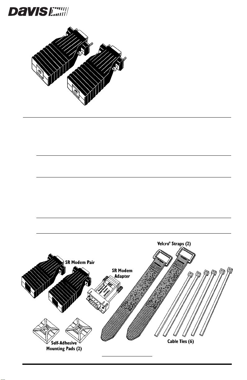
OMPONENTS
The SR Modem includes the components shown below. Please make sure that
you have all the listed components before continuing.
Note:
Please note that we have made every attempt to provide a safe product, but Davis
Instruments assumes no liability for any injury or damage caused directly or indirectly
by the installation or use of this product.
Not shown below is the hardware and manual supplied with the SR Modems. You will need
them to complete the installation, however.
SR M
ODEM COMPONENTS
Product #7875
Page 2

22
19
OOLS AND MATERIALS NEEDED FOR INSTALLATION
T
In addition to the components listed above, you may need the following tools
and materials. Please be sure you have everything you need before beginning
the installation.
Rev. D (or later) WeatherLink Data Logger
✦
All GroWeatherLinks, Health WeatherLinks, and Energy WeatherLinks
use the Rev. D (or later) WeatherLink data logger. If you intend to attach
the SR Modem to Davis’ Perception
Wizard II-S
®
or W eather Monitor II
®
, Weather Wizard III
®
, you need to be sure that you have a
®
, Weather
Rev. D (or later) WeatherLink. Check the manufacturing code on the
underside of the WeatherLink; if it begins with the letter(s) L, LB, or LC,
contact Davis for information on swapping your W eatherLink for the latest version.
2-Twisted-Pair Cable
✦
You will need a length of 2-twisted-pair cable to run between the
SR Modems. Consult the table below to determine the maximum cable
run for either 22 or 19 AWG cables.
AWG
M
AXIMUM
C
ABLE
R
UN
4 Miles (6.4 km)
7 Miles (11 km)
✦
Small Screwdriver
✦
Wire Cutter
Wire Stripper or Knife
✦
L
ABELLING
Y
OUR
C
ABLES
Before beginning the installation, consult your WeatherLink user’s guide for
instructions on labeling the WeatherLink cables.
Page 2 Short-Range Modem Pair
Page 3
NSTALLING
I
THE
HORT
S
R
ANGE
M
ODEM
P
AIR
The SR Modem needs to be installed in a protected location, such as the Complete System Shelter (Davis Product # 7724).
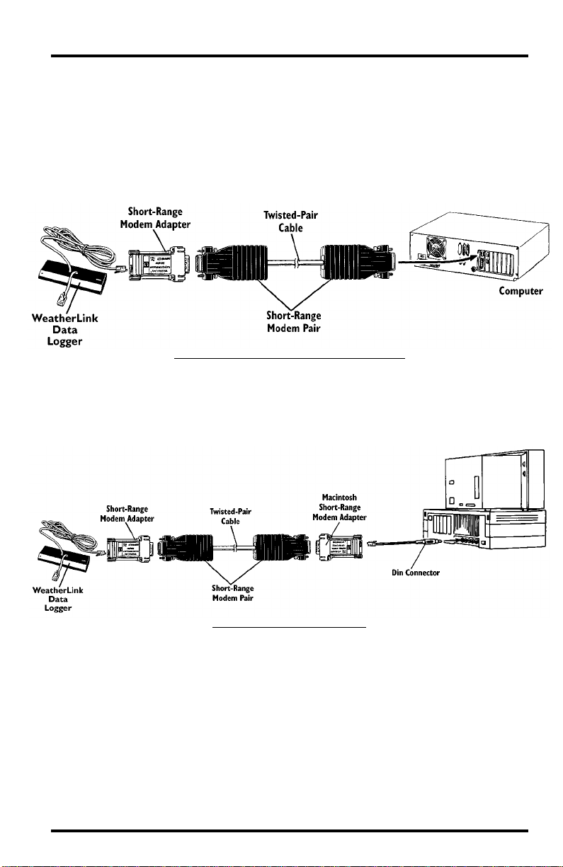
Typical Windows™-Based Computer Connection
The illustration below shows a typical SR Modem connection to a Windowsbased computer.
T
Typical Macintosh
W
YPICAL
®
Connection
INDOWS
-B
ASED
C
OMPUTER
C
ONNECTION
The illustration below shows a typical SR Modem connection to a Macintosh
computer.
T
YPICAL
M
ACINTOSH
C
ONNECTION
Installing the Short Range Modem Pair Page 3
Page 4

Installing the SR Modem in the Complete System Shelter (CSS)
The instructions below will take you through the procedure for installing the
SR Modem into the CSS. If not installing in the CSS, you will need to adapt the
instructions to suit your individual needs.
1. Remove the back panel from the CSS (consult the CSS instruction for instructions).
2. Slide four of the cable ties through the holes in the panel as shown below.
Loosely join the cable ties in back of the panel. Do not tighten yet.
3. Slide the Velcro straps under the cable ties on the front of the panel as shown
below.
4. Secure the Velcro straps in place by tightening the cable ties.
Cut off any excess cable tie.
A
TTACHING
V
ELCRO
S
TRAPS
TO
CSS P
ANEL
5. Pass one end of the twisted-pair cable through the strain relief in the base of the
CSS.
6. Attach the twisted pair cable to the terminal block on one of the SR Modems.
Consult the manual supplied with the SR Modem itself for instructions. If
desired, you may ignore the instructions r egarding installing the captiv e scr ews
and saddle washers in the SR Modem. The captive screws and saddle washers
are not necessary (though all subsequent illustrations show them installed).
Note that we do not recommend connecting the drain wire to ground; cut off
any excess drain wire. For greatest communication range, use unshielded
cable. If shielding is desired (for noise suppression), ground the drain wire
at the computer end of the connection only.
Page 4 Short-Range Modem Pair
Page 5

7. Attach the SR Modem Adapter to the SR Modem.
A
TTACHING
SR M
ODEM
A
DAPTER
SR M
TO
THE
ODEM
8. Secure the SR Modem and SR Modem Adapter to the CSS Panel by placing
them on top of the Velcro straps and tightening the straps as shown below.
S
ECURING
SR M
ODEM
9. Place a self-adhesive mounting pad onto the CSS panel below the SR Modem,
allowing at least 1” (25 mm) as shown below.
10.Position the twisted-pair cable over the mounting pad as shown below.
Installing the Short Range Modem Pair Page 5
Page 6

11.Slide a cable tie into the mounting pad and secure the twisted-pair cable to the
mounting pad by tightening the cable tie.
Cut off any excess cable tie.
S
ECURING
T
WISTED
-P
C
AIR
ABLE
12.Reattach the CSS panel to the CSS and insert the console mounting screws into
the panel (consult the CSS instruction for instructions).
13.Plug the WeatherLink cable into the SR Modem Adapter.
14.Attach the second self-adhesive mounting pad onto the CSS panel as shown
below.
A
TTACHING
W
EATHER
L
C
INK
ABLE
15.Connect the WeatherLink to the console and attach the console to the CSS
panel (consult the necessary manuals for instructions).
Page 6 Short-Range Modem Pair
Page 7

16.Bundle the excess W eatherLink cable together and position the b undle o ver the
mounting pad as shown below.
17.Slide a cable tie into the mounting pad and secure the WeatherLink cable to the
mounting pad by tightening the cable tie.
Cut off any excess cable tie.
S
ECURING
W
EATHER
L
C
INK
ABLE
18.Go to the other end of the twisted-pair cable and attach the twisted pair cable
to the terminal block on the second SR Modem. Consult the manual supplied
with the SR Modem itself for instructions. If desired, you may ignore the
instructions regarding installing the captive screws and saddle washers in the
SR Modem. The captive screws and saddle washers are not necessary (though
all subsequent illustrations show them installed).
Note that we do not recommend connecting the drain wire to ground; cut off
any excess drain wire. For greatest communication range, use unshielded
cable. If shielding is desired (for noise suppression), ground the drain wire
at the computer end of the connection only.
Installing the Short Range Modem Pair Page 7
Page 8

19.Plug the second SR Modem into an available serial port on your PC.
C
ONNECTING
S
ERIAL
P
ORT
TO
Installing the SR Modem in the Multi-Purpose Shelter
Consult the Multi-Purpose Shelter manual for mounting instructions. You will
still need to use the manual supplied with the SR Modem itself for instructions
on connecting twisted-pair cable to the terminal blocks.
Using Surge Protectors with the Short-Range Modem Pair
The SR modems contain 600 Watt surge protectors. If the cable run between
modems is exposed to lightning-induced or other surges, you may want to add
additional surge protectors at one or both ends of the cable. Two Surge Protectors (Davis Product # 7767) housed in a Small Surge Protector Shelter
(Davis Product #7768) are well-suited for this. If the cable is exposed, we suggest the use of one pair of surge protectors where the cable enters the building
containing the computer.
Product Numbers: 7875
Davis Instruments Part Number: 7395-088
Short-Range Modem Pair
Rev. C Manual (7/7/99)
This product complies with the essential protection requirements of the EC EMC
Directive 89/336/EC.
© Davis Instruments Corp. 1998. All rights reserved.
VELCRO is a registered trademark of Velcro Industries, Manchester, NH.
 Loading...