

Page 1
EATER
H
FOR C
OR MULTI-PURPOSE SHELTER
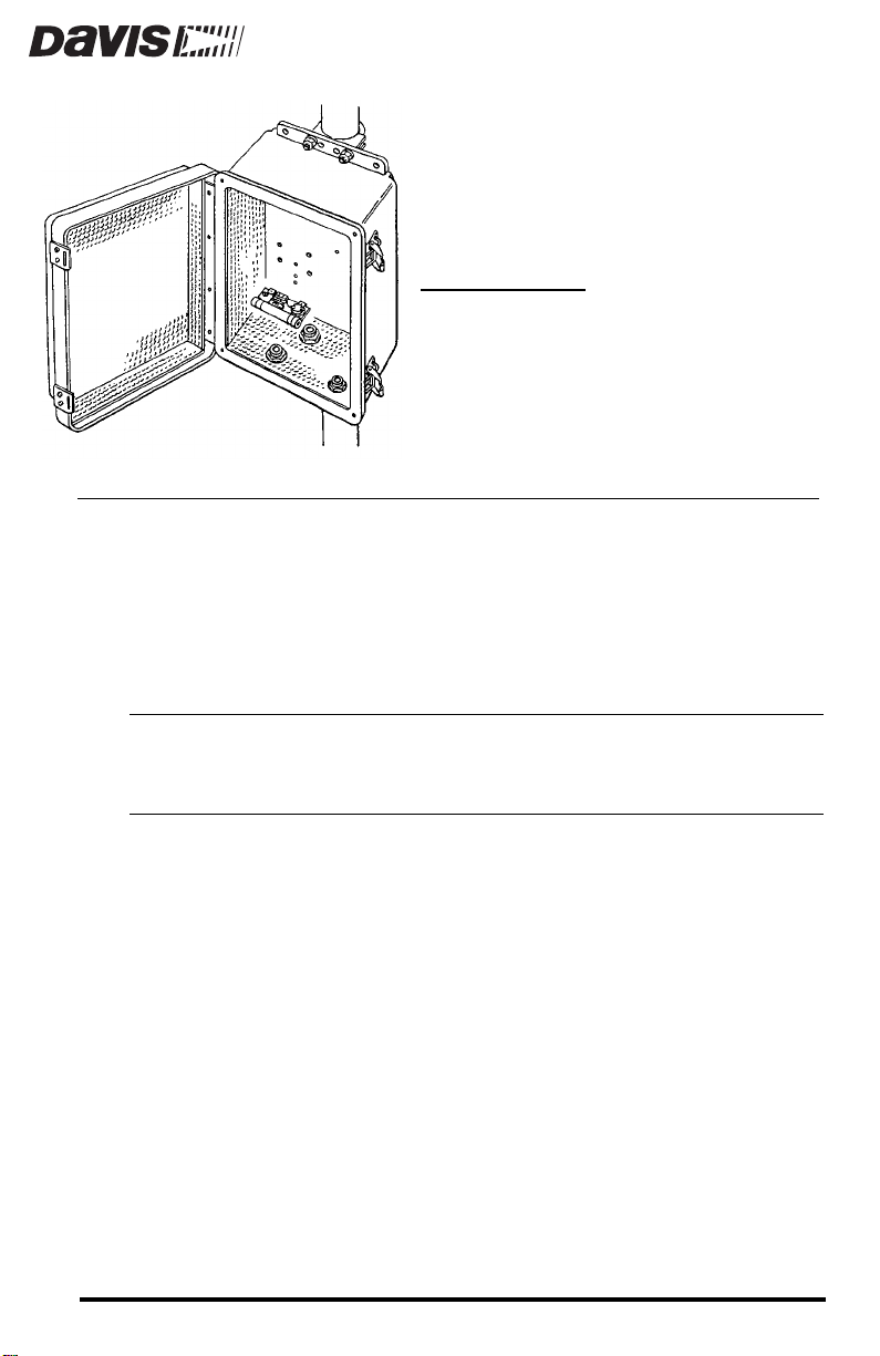
The heater may be used with the Complete System Shelter (CSS) or the MultiPurpose Shelter (MPS). Used with either shelter, it will protect the contents of
the shelter from damage due to cold weather or condensation. Use the heater if
you expect temperatures below 0˚F (-18˚C) or condensation.
Please note that we have made every attempt to design and manufacture a safe
product, but Davis Instruments assumes no liability for any injury or damage
caused directly or indirectly by the installation or use of this product.
CAUTION:
Although the nominal heater voltage is not hazardous, a short in the wall transformer
could cause hazardous voltage to appear on the heater wires. For safety, you should
always turn the heater’s power unit to the “OFF” position before opening the shelter.
We also recommend that you unplug the wall transformer before opening the shelter.
OMPLETE SYSTEM SHELTER
Product #7726, 7730
Page 2
OMPONENTS
C
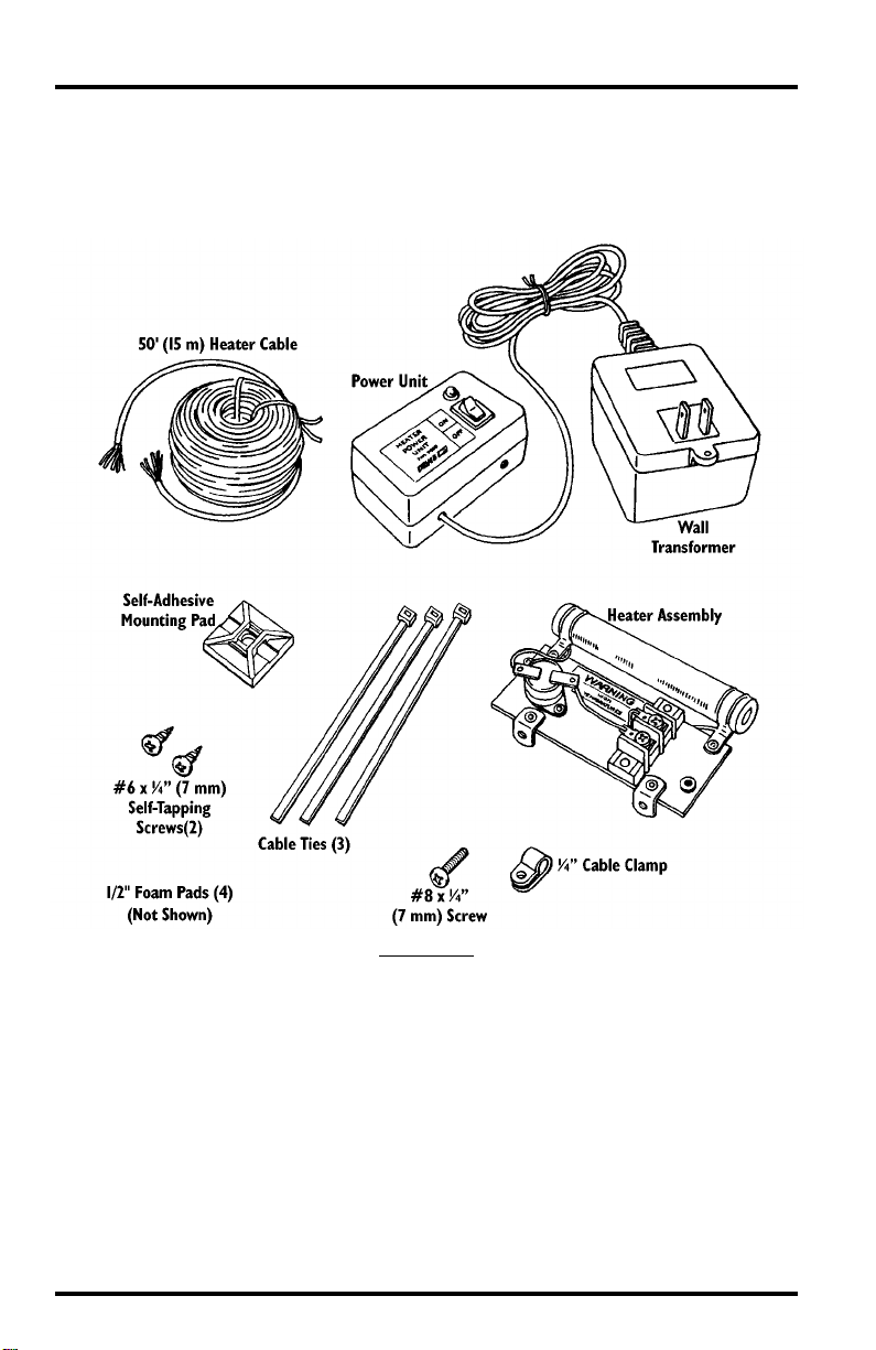
The heater includes components pictured below as well as the insulation blankets pictured on the following page. Please make sure you have all listed components before continuing.
OMPONENTS
C
Page 2 Heater
Page 3
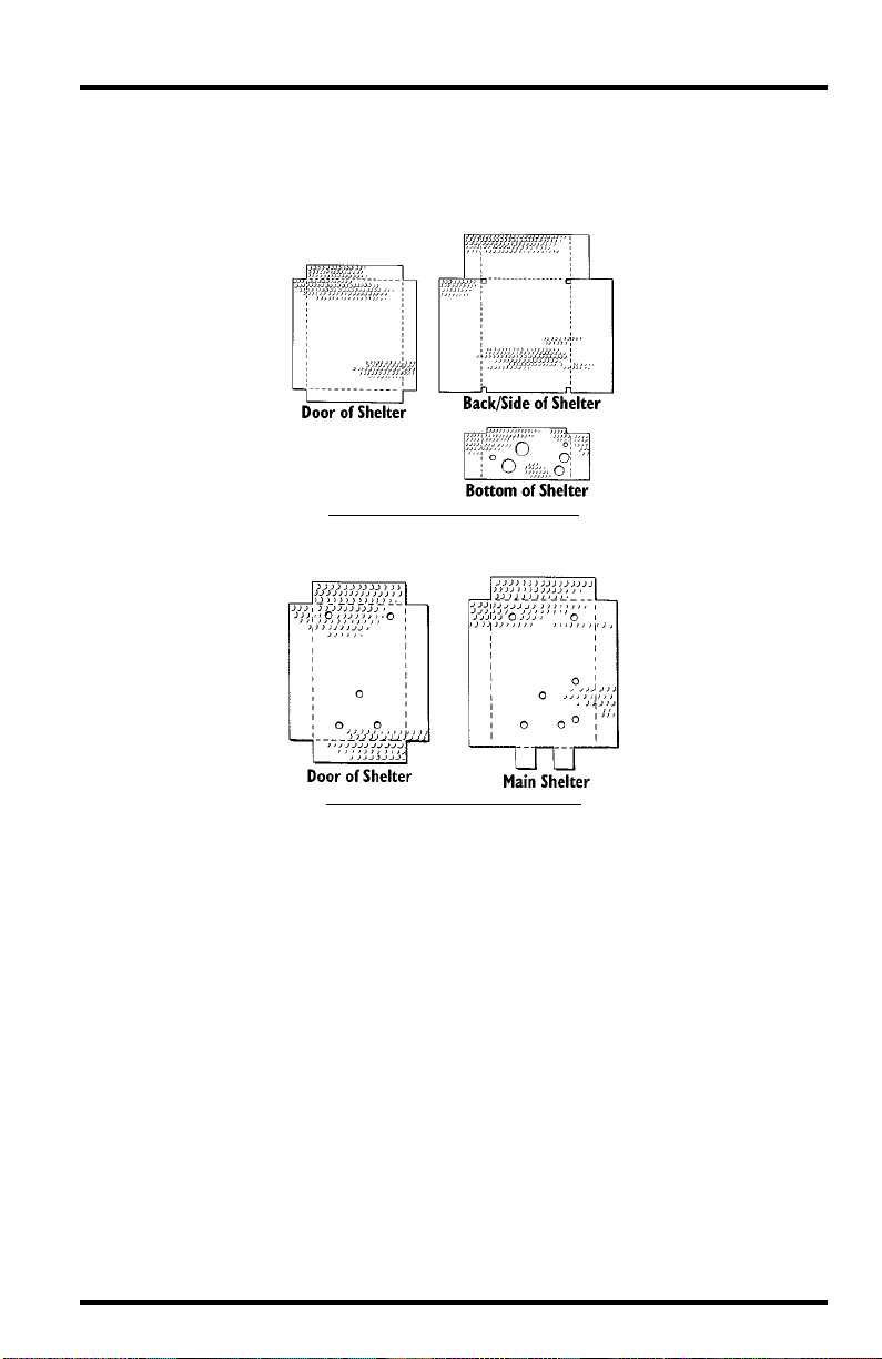
Insulation Blankets
Included in your heater package will be the insulation blankets appropriate for
either the Complete System Shelter or the Multi-Purpose Shelter, as pictured
below.
CSS H
EATER INSULATION BLANKETS
MPS H
EATER INSULATION BLANKETS
T
OOLS
AND
M
ATERIALS
In addition to the components listed above, you will need some of the following tools and materials. Please be sure you have everything you need before
beginning the installation.
Medium Phillips Screwdriver
✦
Wire Cutter
✦
✦
Wire Stripper or Knife
Cable Clips or Weather-Resistant Cable Ties
✦
Tools and Materials Needed for Installation Page 3
N
EEDED
FOR
I
NSTALLATION
Page 4

)
Choosing Cable for the Heater
The heater comes with a 50-foot (15 m) length of 22 gauge, two twisted-pair
cable. When using this cable, the red and white wires are joined and used as
one wire and the two black wires are joined and used as one wire. You may use
22 gauge, two-twisted pair wire in this manner for cable lengths up to 120 feet
(36 m). If you want to use single pair cable, use the following table to determine the minimum wire size for the desired length of cable run.
ENGTH
OF
ABLE
L
C
R
UN
Up to 60 feet (18 m) 22AWG (0.50 mm
60-100 feet (18-30 m) 20AWG (0.75 mm
100-160 feet (30-50 m) 18AWG (1.0 mm
160-250 feet (50-80 m) 16AWG (1.50 mm
INIMUM
M
W
IRE
2
)
IZE
S
2
)
2
)
2
If the heater cable is routed with a system signal cable, be aware that for cable
runs over 50 feet (15 m), you need to do at least one of the following to prevent
the heater cable’s voltage from interfering with sensor voltages.
✦
Use twisted pair for the heater cable or the signal cable.
Use shielded cable for the heater cable or signal cable (shield must be
✦
grounded).
✦
Keep the heater cable and the signal cable separated by several inches (at
least 8 cm) over most of the length of the cable run.
Page 4 Heater
Page 5

NSTALLING
I
THE
NSULATION
I
LANKETS
B
AND
EATER
H
Follow the instructions below to install the insulation blankets and the heater
in the appropriate shelter.
Installing in the Complete System Shelter
1. Remove the panel from the back of the CSS.
Consult your CSS manual for instructions.
2. Crease and fold the CSS insulation blankets as shown below.
Make sure the adhesive strips on the blanket are on the back of the blanket
(the side not shown below).
C
REASE
AND
F
OLD
CSS I
NSULATION
B
LANKETS
3. Try inserting the blank ets into the CSS to mak e sur e they fit. Adjust the folding
as necessary to make them fit.
4. Once you are sure the blankets will fit, remove the backing from the adhesive
strips on the insulation blankets and secure the blankets in the CSS.
Make sure the blankets do not cover the four screw holes in the corner of the
CSS.
I
NSTALLING
B
LANKET
INTO
CSS
Installing the Insulation Blankets and Heater Page 5
Page 6

5. Reattach the panel to the back of the CSS as shown below.
R
EATTACH
P
ANEL
B
ACK
OF
CSS
TO
6. Attach the heater to the panel using the #6 screws as shown below.
A
H
EATER
TO
CSS
TTACH
Installing in the Multi-Purpose Shelter
1. Crease and fold the MPS insulation blankets as shown below.
Make sure the adhesive strips on the blanket are on the back of the blanket
(the side not shown below).
C
F
REASE
AND
OLD
MPS I
NSULATION
B
LANKETS
Page 6 Heater
Page 7

2. Try inserting the blank ets into the MPS to make sur e they fit. Adjust the f olding
as necessary to make them fit.
3. Once you are sure the blankets will fit, remove the backing from the adhesive
strips on the insulation blankets and secure the blankets in the MPS.
I
NSTALLING
B
LANKET
INTO
MPS
4. You may install the heater in one of three locations in the MPS, as shown below.
Secure the heater to the MPS using the #6 screws.
Consult your MPS manual to determine the best mounting location for the
heater in your case.
R
OUTING
THE
H
EATER
I
NSTALLING
C
H
THE
ABLE
EATER
MPS
IN
THE
Follow the instructions below to route the heater cable from the heater to the
power unit.
Attaching Heater Cable to Heater
1. Route the cable into the shelter through one of the cable boots at the base of the
shelter.
2. If using the provided cable, twist the Red & White wires together to create a
single wire and twist the two Black wires together to create a single wire.
The bare wire may simply be cut off.
Routing the Heater Cable Page 7
Page 8

3. Bend each bare wire into a U-shape and secure each one under a screw head on
the terminal block as shown below.
It does not matter which wire goes to each screw as long as only one wire
goes to each screw.
A
TTACHING
CABLES
TO
T
ERMINAL
B
LOCK
4. Secure the cable to the heater assembly by placing the π ” cable clamp over the
cable and securing it to the heater assembly as shown below.
S
ECURING
C
ABLE
H
EATER
A
SSEMBLY
TO
Page 8 Heater
Page 9

5. For strain relief, attach the self-adhesiv e mounting pad to the wall of the shelter
and use a cable tie to secure the heater cable, as shown below.
S
ECURING
H
EATER
C
I
NSIDE
S
HELTER
ABLE
Routing the Cables
Route the heater cable to the location at which you plan to plug in the wall
transformer/power unit. To prevent fraying or cutting of the cable where it is
exposed to weather, it is very important that you secure it so it doesn’t whip
about in the wind. Use cable clips or weather resistant cable ties to secure the
cable outside the shelter. Place clips or ties approximately every 3 to 5 feet
(1 to 1.6 m). Do not use metal staples or a staple gun to secure cables. Metal staples—especially when installed with a staple gun—have a tendency to cut the
cables.
Note:
If your cable run extends more than 50 feet (15 m), keep the heater cable and any signal
cable separated by at least a few inches, as discussed in “Choosing Cable for the Heater”
on page 4.
Attaching Cable to Power Unit
1. Remove the base of the power unit by removing the four screws in the base.
2. Loosen the screw heads on the terminal block.
You will eventually secure the heater cable wires underneath these screw
heads.
3. Using wire strippers or a knife, strip 3/8” (10 mm) of insulation from the heater
cable wires.
4. Feed the cable through the hole in the power unit.
5. If using the provided cable, twist the Red & White wires together to create a
single wire and twist the two Black wires together to create a single wire.
The bare wire may simply be cut off or connected to ground if you wish to
make use of the shield in the cable.
Routing the Heater Cable Page 9
Page 10

6. Bend each bare wire into a U-shape and secure under a screw head on the terminal block, as shown below.
It does not matter which wire goes to each screw as long as only one wire
goes to each screw.
P
OWER UNIT TERMINAL BLOCK
7. To provide strain relief for the cable, place a cable tie around the cable just
inside the hole through which this cable is running as shown below.
You may need to cut off the excess cable tie in order to close the power unit.
P
ROVIDING STRAIN RELIEF
8. Replace the base of the power unit.
9. You may now plug the wall transformer into an outlet.
10.To insure that the heater is working, you may want to set the power unit to the
“ON” setting and then go to the Rain Collector to insure that the heater element is hot.
DO NOT TOUCH THE HEATER ELEMENT OR ANY METALLIC PORTION OF THE HEATER.
You should be able to feel the heat at a short dis-
tance from the heater element.
Page 10 Heater
Page 11

SING THE HEATER
U
You may switch the heater on and off from the power unit.
✦
OFF
When the heater is off, the indicator light on the power unit is also off.
ON
✦
When the heater is set to “ON,” the indicator light on the power unit is
also on.
The heater assembly includes a thermostat switch. If the temperature at the
thermostat reaches 80˚F (27˚C) the thermostat will interrupt power to the
heater element. When the temperature at the thermostat drops to about 50˚F
(10˚C) power flow to the heater element will be resumed.
L
OCATION OF THERMOSTAT
Using the Heater Page 11
Page 12

Product Numbers: 7726, 7730
Davis Instruments Part Number: 7395-097
Complete System Shelter Heater, Multi-Purpose Shelter Heater
Rev. B Manual (7/7/99)
Controlled Online: Weather:Accessories:Shelter Heaters
This product complies with the essential protection requirements of the EC EMC Directive 89/336/EC.
© Davis Instruments Corp. 1998. All rights reserved.
3465 Diablo Avenue, Hayward, CA 94545-2778
510-732-9229 • Fax: 510-732-9188
E-mail: info@davisnet.com • www.davisnet.com
 Loading...