

Page 1
UV S
ENSOR
FOR S
I
P
The UV Sensor is a precision instrument that detects ultraviolet (UV) radiation
at wavelengths of 290 to 390 nanometers. The spectral response is closely
matched to the Erythema Action Spectrum, defined by McKinlay and Diffey
(1987) and internationally recognized as the radiation that is most responsible
for causing redness of the human skin.
Avoid touching the small white diffuser at the top of the sensor.
on this surface will degrade the sensitivity of the sensor. To remove any oil
present, clean the diffuser with a clean swab and ethyl (denatured) alcohol. Do
NOT use rubbing alcohol.
Note:
It should be noted that sunburn is not the only consequence of exposure to UV radiation. Skin cancers,
cataracts, and damage to the immune system are caused by UV. Exposure to UV should be minimized.
The sensor is made up of the following components:
✦
Shield
The outer shell shields the sensor body from thermal radiation and provides a path for convection cooling of the body, minimizing heating of
the sensor interior. It provides a cutoff ring for cosine response, a level
indicator, and fins to aid in aligning the sensor with the sun’s rays.
Body, housing the following components:
✦
✦
Cap
Retains the diffuser and filter
Diffuser
✦
Provides (with gasket) a weather-tight seal and excellent cosine response.
✦
Filter
With multiple hard-oxide coatings, the filter pr ovides the Erythema
Action spectral response. It is stable in the presence of heat and humidity.
✦
Detector
The semiconductor diode, with the filter , responds only to radiation in the
region of interest.
✦
Amplifier
Converts the detector current into a 0 to +2.5V signal.
Cable
✦
The standard version of the sensor includes an attached standard 40'
(12 m) cable. The industrial version includes a 16' (5 m) shielded cable.
The V antage Pr o version includes a standar d 3' (0.9 m) cable.
TANDARD
NDUSTRIAL
,
, & V
ANTAGE
RO WEATHER STATIONS
Any skin oil
Product # 7841, 7843, 6490
Page 2
OUNTING
M
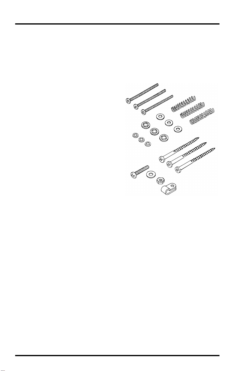
Please make sure you have all components listed below before continuing.
ARDWARE
H
✦
Shield
Body with cable attached
✦
✦
Mounting hardware
Enables installation and
leveling of the sensor.
Three #6-32 x 1-1/2"
✦
(38 mm) machine screws
Three springs
✦
✦
Three #6 flat washers
✦
Three #6 screw retainers
Three #4 screw retainers
✦
✦
Three wood screws
One #8-32 x 3/4" (19 mm)
✦
machine screw
✦
One #8-32 hex nut
One #8 flat washer
✦
✦
One 3/16" (5 mm) cable
clamp
T
OOLS
AND
M
ATERIALS
Y ou may need some of the following tools and materials in or der to complete your
installation. Please be sure you have everything you need before beginning.
✦
Medium Phillips screwdriver
✦
Center punch or nail (if mounting on wood surface)
Drill with 7/8" (22 mm) and #36 (2.7 mm) drill bits (if mounting on wood surface)
✦
✦
Wire cutters and stripper (industrial version only)
Page 2 UV Sensor
N
EEDED
Page 3

ONTENTS
C
Standard and Industrial Versions: Installation.............................. 3
Testing the Sensor.......................................................................... 3
Installing the Sensor....................................................................... 4
Typical Standard Installation......................................................... 4
Typical Industrial Installation........................................................ 5
Mounting on the Sensor Mounting Arm......................................... 6
Mounting on the Sensor Tilting Bracket........................................ 7
Mounting on a Wood Surface.......................................................... 10
Routing Sensor Cable..................................................................... 10
Vantage Pro Version: Installation on the Sensor Mounting Shelf.. 12
Testing the Sensor.......................................................................... 12
Accessing the SIM........................................................................... 12
Securing the Sensor on the Shelf.................................................... 13
Routing Sensor Cable..................................................................... 14
If You Are Going to Install the Solar Radiation Sensor................. 15
Maintaining the Sensor.................................................................. 15
Technical Support.......................................................................... 16
S
PECIFICATIONS
For detailed technical information on the UV sensor, call Technical Support
(510) 732-7814 to request a specification sheet, or download it from our website:
http://www.davisnet.com/support/weather/
S
TANDARD
Testing the Sensor
1. Attach the sensor cable to the connector S3 on the sensor interface module, or “SIM”.
Consult the System Installation manual for instructions.
2. Press UV on the Health EnviroMonitor to make sure you are getting a UV reading.
Consult the Health EnviroMonitor manual for instructions on displaying UV.
3. Shade the sensor and make sure the reading drops.
Contents Page 3
AND
A
ARE
VAILABLE
I
NDUSTRIAL
V
ERSIONS
: I
NSTALLATION
Page 4
Installing the Sensor
Follow the instructions in this section to install your sensor. Before you begin,
consult the System Installation manual for instructions on labeling the UV sensor cable.
✦
For scientific measurements you may mount the sensor on the Sensor Mounting
Arm (SMA) or any level surface.
✦
For measurements where the immediate effect on human health is of interest, we
recommend that you mount the sensor such that its axis is aligned with the sun’s
rays at solar noon.
This maximizes the mid-day readings and provides what is probably a
more accurate measure of the UV that people are exposed to. The Sensor
Tilting Bracket #7706 is designed for this purpose.
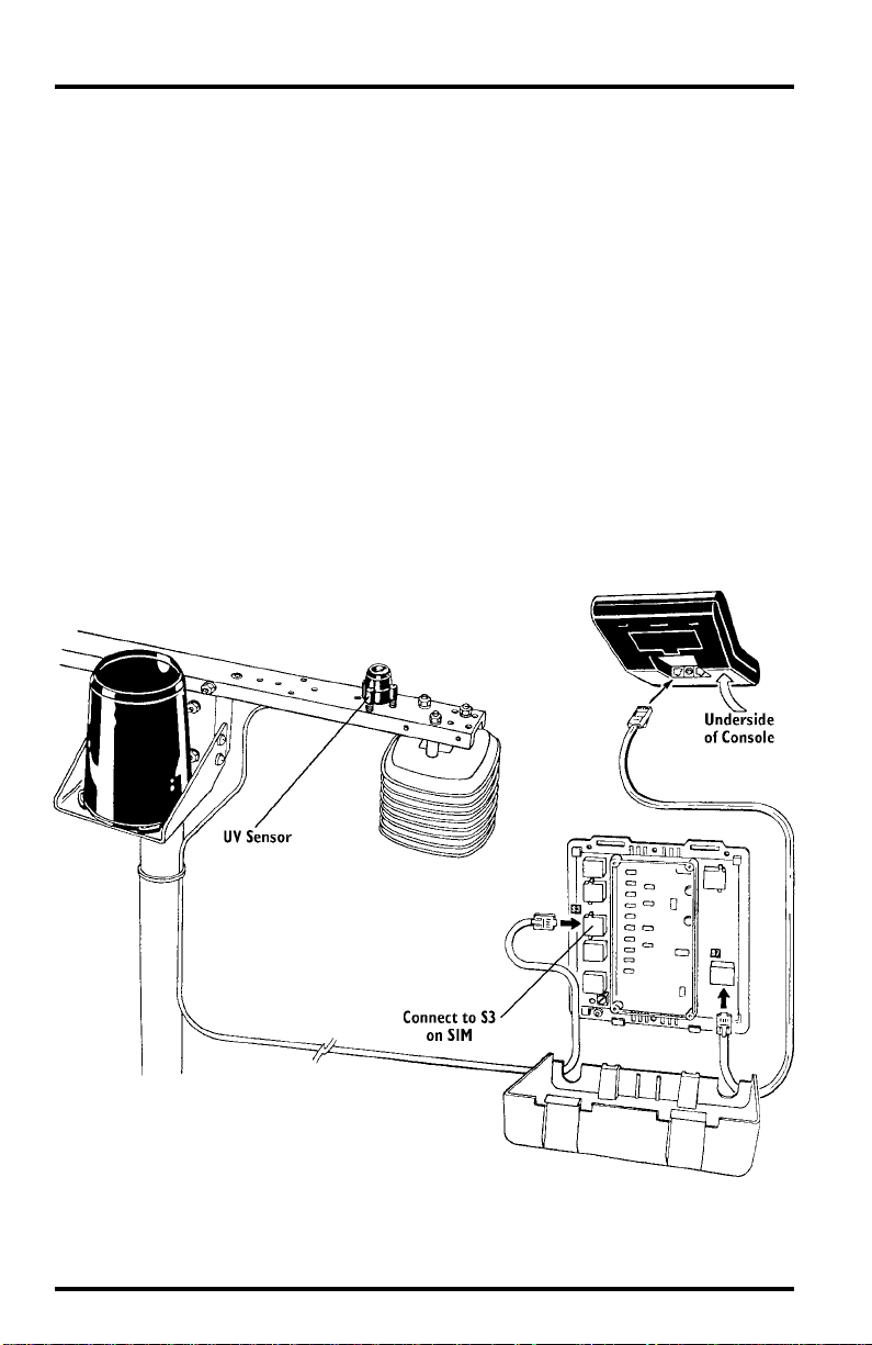
Typical Standard Installation
The illustration below shows typical standard UV installation. The sensor cable
attaches to connector S3 on the sensor interface module (SIM).
T
YPICAL
S
TANDARD
I
NSTALLATION
Page 4 UV Sensor
Page 5
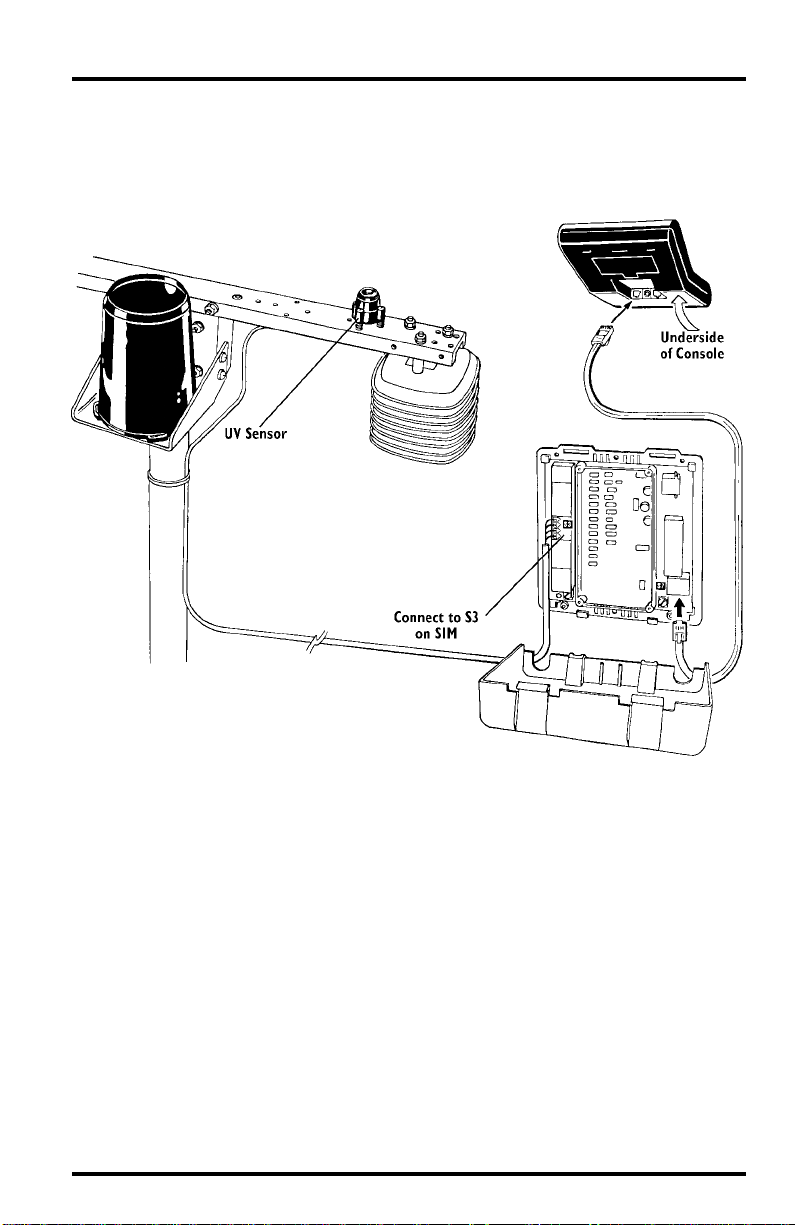
Typical Industrial Installation
The illustration below shows typical industrial UV installation. The sensor
cable attaches to connector S3 on the sensor interface module (SIM).
T
YPICAL
I
NDUSTRIAL
I
NSTALLATION
Standard and Industrial Versions: Installation Page 5
Page 6

Mounting on the Sensor Mounting Arm
Follow the instructions below to mount the sensor on the Sensor Mounting Arm (SMA).
1. Route the sensor cable through the large hole in the mounting arm if desired.
2. Place the shield onto the body as shown below.
LACING
HIELD
ONTO
P
S
ODY
B
3. Place a flat washer over the end of each screw and insert it into the body.
4. Place a spring over the end of each screw and hold the springs in place using a #6
screw retainer.
5. Secure the sensor to the mounting arm by driving the screws into the appropriate
holes as shown below.
OUNTING
THE
ENSOR
ON
M
UV S
THE
SMA
Page 6 UV Sensor
Page 7

6. Using the bubble level on the sensor as a guide, adjust the sensor until it is level by
tightening or loosening the screws as necessary.
7. Secure the sensor cable to the underside of the mounting arm using the 3/16" cable
clamp, #8-32 x 3/4" screw, #8 hex nut, and #8 flat washer as shown below.
S
ECURING
S
ENSOR
C
ABLE
Mounting on the Sensor Tilting Bracket
Follow the instructions below to mount the sensor on the Sensor Tilting
Bracket. Do not install the bracket onto the mounting arm until instructed to do
so below.
1. Route the sensor cable through the large hole in the bracket if desired.
2. Place the shield onto the body as shown below.
LACING SHIELD ONTO BODY
P
Standard and Industrial Versions: Installation Page 7
Page 8

3. Place a flat washer over the end of each screw and insert it into the body.
4. Place a spring over the end of each screw and hold the springs in place using a #6
screw retainer.
5. Secure the sensor to the sensor tilt bracket by driving the screws into the appropriate
holes as shown below.
If mounting the sensor on the tilting bracket in a location under 46˚ latitude
or in a situation which requires the angle of the tilting bracket to be less than
28˚, you will need to use the standoffs supplied with the tilting bracket. Consult the Sensor Tilting Bracket manual for details.
OUNTING THE
M
ENSOR ON THE SENSOR TILTING BRACKET
UV S
6. Position the Sensor Mounting Arm so it is pointed in the direction of the sun at solar noon.
Solar noon occurs halfway between sunrise and sunset; consult your local paper
or the W eatherLink
®
software for sunrise and sunset times. To correctly align
the arm, screw a mounting screw part way into any of the sensor’s screw positions on the mounting arm and rotate the arm until the shadow from the screw
is parallel to the edge of the sensor arm at solar noon.
7. Attach the bracket to the mounting arm as described in the Sensor Tilting Bracket
instruction manual.
If you are installing both the solar radiation and the UV sensor on the sensor
tilting bracket, make sure you mount the solar radiation sensor on the sensor tilting bracket before attaching to the sensor mounting arm.
Page 8 UV Sensor
Page 9

8. If necessary, adjust the position of the sensor by tightening or loosening the levelling
screws.
When pointed directly at the sun, the shadows from the alignment fins
should appear as shown in the illustration below.
F
INAL SENSOR POSITIONING
9. Secure the sensor cable to the underside of the mounting arm using the 3/16" cable
clamp, #8-32 x 3/4" screw, #8 hex nut, and #8 flat washer as shown below.
ECURING SENSOR CABLE
S
Standard and Industrial Versions: Installation Page 9
Page 10

Mounting on a Wood Surface
Follow the instructions below to mount the sensor on a wood surface.
1. Using the template printed at the bottom of this page, mark the location of the necessary pilot holes.
2. Using a drill with a #36 (2.7 mm) drill bit, drill pilot hole in the marked locations. If
necessary, bore a hole through the mounting surface using a 7/8" (22 mm) drill bit so
the bottom of the sensor can sit inside of it and the sensor cable can run to the other
side.
3. Route the sensor cable through the hole in the wood if desired.
4. Place the shield onto the body as shown below.
PLACING SHIELD ONTO BODY
5. Place a flat washer over the end of each screw and insert it into the body.
6. Place a spring over the end of each screw and hold the springs in place using a #4
screw retainer.
Use the template below to center-punch or mark pilot holes before drilling.
UV SENSOR MOUNTING HOLES TEMPLATE
Page 10 UV Sensor
Page 11

7. Secure the sensor to the mounting surface by driving the screws into the appropriate
holes as shown below.
MOUNTING THE UV SENSOR ON A WOOD SURFACE
8. Using the bubble level on the sensor as a guide, adjust the sensor until it is level by
tightening or loosening the screws as necessary.
9. Secure the sensor cable to the mounting surface. Y ou may use the provided 3/16" cable
clamp, #8-32 x 3/4" screw, #8 hex nut, and #8 flat washer if possible.
Routing Sensor Cable
To prevent fraying or cutting of the
cable where it is exposed to weather,
secure it so it doesn’t whip about in
the wind. Use cable clips or weather
resistant cable ties to secure the
cable. Place clips or ties approximately every 3 to 5 feet (1 to 1.6 m).
Do NOT use metal staples or a staple
gun to secure cables. Metal staples—
especially when installed with a staple gun—have a tendency to cut the
Cable Clip
Cable Tie
cables.
Note:Try not to tug on the cable in such a way as to loosen the connections between cables. Also,
make sure the sensor cable is not so taut that connections loosen or pull free due to the
strain. Many sensor problems occur because cable connections come loose.
Standard and Industrial Versions: Installation Page 11
Page 12

VANTAGE PRO VERSION : INSTALLATION ON THE MOUNTING SHELF
Follow these instructions to mount the UV sensor on the shelf. The shelf has
two large holes, to hold a UV sensor and a solar radiation sensor. It doesn’t
matter which hole you use first.
Testing the Sensor
On Vantage Pro’s Integrated Sensor Suite (ISS), the sensor interface module, or
SIM, is inside the radiation shield. (The SIM is where the sensors connect with
the rest of the weather station). You need to remove the radiation shield plates
to access the SIM and test the UV sensor. Take your console with you.
On the rain collector side of your ISS, underneath the white mounting base is
the radiation shield. It consists of several white plastic plates.
Accessing the SIM
1. Remove the wing nuts, lock
washers and flat washers.
2. Remove the first three plates
of the radiation shield.
Y ou should now be able to
see the SIM.
3. Plug the UV sensor cable into the receptacle labeled “UV” on the SIM.
Hold the sensor body with
white diffuser pointed
upward. Do NOT touch
the diffuser. If you do,
clean it after mounting.
(See “Maintaining the Sensor” on page 15.)
4. On your console, press the “UV” key to see the reading.
Shade the sensor with
your hand — the value
should drop.
5. Unplug the sensor cable from the SIM.
Sensor
Interface
Module
(SIM)
Antenna
deployment
hole (used on
Wireless only)
Mounting Base
Open Plate
Open Plate
Closed Plate
Do not put the shield plates
#8 Flat Washer
back on yet. You’ll have to
plug the sensor cable into the
SIM again, once you have
mounted the sensor.
#8 Lock Washer
#8 Wing Nut
Page 12 UV Sensor
Page 13

Securing the Sensor on the Shelf
1. Remove the rain collector cone: turn it counter-
clockwise until the latches allow you to lift it up
and off.
2. Place the sensor shield onto the sensor body as
shown here.
3. Route the sensor cable down through one of the
large holes in the mounting shelf.
4. Place a flat washer over the end
of each screw and insert it into
the body.
5. Place a spring over the end of
each screw and hold the
springs in place using a #6
screw retainer.
6. Secure the sensor to the
mounting shelf by driving the
screws into the appropriate
holes as shown.
7. Using the bubble level on the
sensor as a guide, adjust the
sensor until it is level by tightening or loosening the screws.
Note:Final leveling of the sensor(s) should be done with the ISS mounted in its operating location.
Vantage Pro Version: Installation on the Mounting Shelf Page 13
Page 14
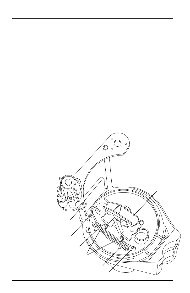
Routing the Sensor Cable
Route the sensor cable through the base of the rain collector and out through a
hole, then connect it to the SIM inside the radiation shield. (This step requires
that the radiation shield is open. If it is not, remove the shield plates now as
shown in “Accessing the SIM” on page 12.)
See the illustration below as you follow these instructions.
1. Tie the sensor cable to the shelf support tube.
Use one of the plastic 4" cable ties provided with the sensor mounting shelf
to keep the cable in place. (#1 in illustration.)
2. Squeeze the cable down into the cable notch on the circular edge of the rain collector
base. The cable needs to be wedged down into the notch so it will come up inside the
rain collector cone when the cone is put back on.
3. Route the cable down and out through the hole in the base.
Plug the cable into the receptacle labeled “UV" in the SIM, to see how much
slack will be left in the cable as you secure it inside the rain collector.
4. In the rain collector base, loop up the slack in the cable. Using the two cable clamps in
the base, secure one loop.
Tie the remaining loops of cable together with cable ties #2 & 3 as shown.
When securing
the sensor cable(s)
inside the rain collector base, the
goal is to ensure
that the cables do
not interfere with
the tipping
bucket mechanism of the rain
collector.
Cable Tie #1
Tipping Bucket
Cable Notch
Cable Tie #2
Cable Clamps
Cable Tie #3
NOTE: Route sensor cable(s) out through this hole
Page 14 UV Sensor
Page 15

5. Cut off the ends of the cable ties.
6. Put the rain collector cone back on the base, turning it clockwise until the latches
hold it in place. Be sure that it does not squeeze the sensor cable where it goes
down into the notch and up inside the cone.
Don’t put the cone back on if you’re going to install the solar radiation sensor at this time.
7. Clean the sensor as instructed in “Maintaining the Sensor” on page 15.
If You Are Going to Install the Solar Radiation Sensor
If you’re installing the solar radiation sensor also, use the same testing and
installation procedure completed for the UV sensor. In the rain collector base,
the cable clamps have room to secure one loop of the UV sensor cable and one
loop of the solar radiation sensor cable.
Reassembling Radiation Shield
Consult the illustration on page 12.
1. Slide the two open plates over the threaded studs.
2. Slide the single closed plate over the threaded studs.
3. Place a flat washer, lock washer and wing nut over one of the studs.
Tip: temporarily place a wing nut on one of the studs to hold the plates as
you place washers and a wing nut on another stud.
4. Finger-tighten the wing nut.
5. Repeat #3. and #4. until all three wing nuts are secure.
MAINTAINING THE SENSOR
For the most accurate readings, clean the diffuser after mounting, and then
periodically. Use ethyl alcohol (NOT rubbing alcohol).
Due to the sensitivity of ultraviolet radiation sensors it is common practice for
manufacturers to recommend re-calibration after a period of time. Here at
Davis Instruments we have seen approximately 2% drift per year on the readings from these sensors. For applications demanding higher accuracy, the sensors should be calibrated once every year.
Contact Technical Support (510) 732-7814 about returning your sensor for calibration.
Maintaining the Sensor Page 15
Page 16

TECHNICAL SUPPORT
Before calling Technical Support (510) 732-7814 regarding a problem with your
sensor, carefully check all cable connections from the sensor to the console.
Cable connections account for a large portion of the potential problems. Connections should be firmly seated in the jacks and plugged in straight. If you
think a connection may be faulty, try jiggling the cable while looking at the display. If a reading appears intermittently on the display as you jiggle the cable,
the connection is faulty.
Product Numbers: 7841, 7843, 6490
Davis Instruments Part Number: 7395.095
UV Sensor, Standard, Industrial, & Vantage Pro versions
Rev. C Manual (1/12/01)
This product complies with the essential protection requirements of the EC EMC
Directive 89/336/EC.
Copyright ©2000 Davis Instruments Corp. All rights reserved.
 Loading...