

Page 1
Product numbers 6331 & 6332
USER
MANUAL
Sensor
Transmitter
Davis Instruments, 3465 Diablo Avenue, Hayward, CA 94545-2778 U.S.A. • 510-732-9229 • www.davisinstruments.com
R
Page 2

FCC Part 15 Class B Registration Warning
This equipment has been tested and found to comply with the limits for a class B digital device, pursuant to
Part 15 of the FCC Rules. These limits are designed to provide
reasonable protection against harmful interference in a residential installation. This equipment generates,
uses and can radiate radio frequency energy and, if not installed and used in accordance with the
instructions, may cause harmful interference to radio communications. However, there is no guarantee that
interference will not occur in a particular installation.
If this equipment does cause harmful interference to radio or television reception, which can be determined
by turning the equipment off and on, the user is encouraged to try to correct the interference by one or more
of the following measures:
• Reorient or relocate the receiving antenna.
• Increase the separation between the equipment and receiver.
• Connect the equipment into an outlet on a circuit different from that to which the receiver is
connected.
• Consult the dealer or an experienced radio/TV technician for help.
Changes or modifications not expressly approved in writing by Davis Instruments may void the user's authority to operate this equipment.
Page 3
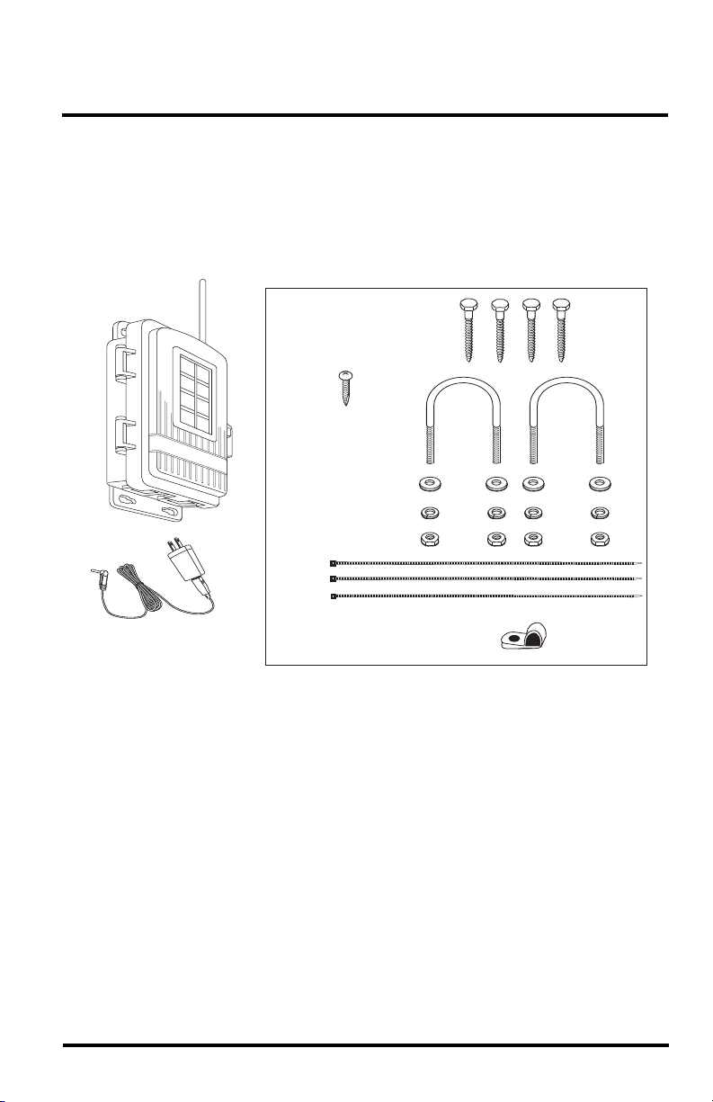
SENSOR TRANSMITTERS
1/4" Flat Washers
1/4" Lock Washers
1/4" Hex Nuts
U-Bolts
1/4" x 1-1/2" Lag Screws
8"
Cable
Ties
AC Adapter
(AC model only)
#6 x 1/2" (3.5 x 12 mm)
Self-Threading Screw
Cable Clamp
SOLAR-POWERED AND AC-POWERED
The Sensor Transmitter enables you to create a customized wireless sensor station that
can communicate directly with your Vantage Pro2 console, Vantage Connect, or
WeatherLink Live. Each transmitter can support up to five different sensors. It comes in
two versions: Solar-powered or AC-powered for indoor installations.
Components
The Sensor Transmitter includes the following components and mounting hardware:
Tools for Setup
In addition to the kit, you will need some or all of the following materials:
• Adjustable wrench or 7/16" wrench
• Compass or local area map
• Ballpoint pen or paper clip (small pointed object of some kind)
• Drill and 3/16" (5 mm) drill bit (if mounting on a vertical surface)
• Carpenter’s level (if mounting on a vertical surface)
Steps in installing your Sensor Transmitter
• Prepare the Sensor Transmitter and plug in the sensor(s)
• Set the transmitter ID using DIP switches
• Choose a location for the Sensor Transmitter
• Install sensors and test transmission from the proposed mounting location
• Mount the Sensor Transmitter
1
Page 4
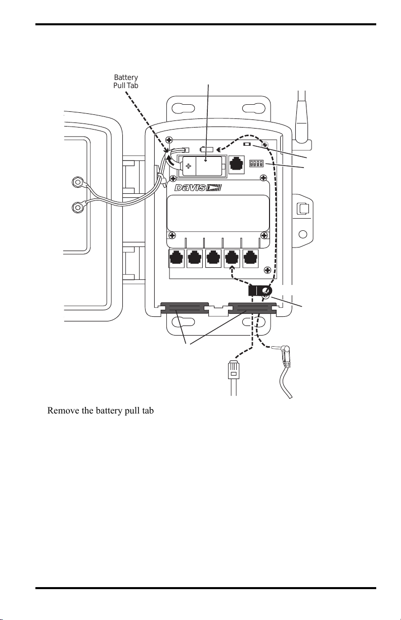
Prepare the Sensor Transmitter
Battery
Pull Tab
DIP Switches
Cable Clamp
Mount
Sensor
Cable
(Anemometer
Shown)
AC- Power
Adapter
Cable
(AC Model Only)
Square Black Grommets
SENSORSENSOR
INTERFACEINTERFACE
MODULEMODULE
UVUV SUNSUN
RAINRAIN WINDWIND
TEMPTEMP
HUMHUM
+
-
Cable Clamp
Test LED
3-Volt
Lithium Battery
The illustration below shows the sensor interface inside the Sensor Transmitter.
1. Remove the battery pull tab and make sure the battery is firmly seated in the battery compartment.
2. AC-powered model only: Push the power cable up through the square black grommet on the bottom right. Plug it into the power jack above the battery compartment.
3. Push the ends of the sensor cables up through the square black grommet of one of the weather-resistant entrances for cables.
Tip: You might find it easier to remove the grommet, thread the cable through it and then replace the
grommet.
4. Plug each sensor cable into the correct receptacle according to the label above each
receptacle.
See “Installing Sensors” on page 7.
5. You may place a cable clamp over the cable (or two cables) between the grommet and
the receptacle. Secure the cable clamp to the shelter by threading the provided #6
screw through the washer, then cable clamp and then screwing it into the cable clamp
mount inside the housing.
2
Page 5

Set the Transmitter ID
1234
ON
Battery Holder
DIP Switches
Each wireless transmitter (such as a Vantage Pro2 sensor suite or a Sensor Transmitter)
must be set to a different one of eight transmitter IDs. Set the transmitter ID using the
DIP switches inside the sensor interface.
DIP switches #1, 2 and 3 allow you to control the ID — the “channel” it will transmit on.
(DIP switch #4 is used for transmission testing, not for transmitter ID.)
Note: The transmitter and your receiver (console, WeatherLink Live, Vantage Connect) communicate
with each other only when both are set to the same ID.
The factory default transmitter ID is ‘1’. Your Vantage Pro2console/receiver is factoryset to find a Vantage Pro2 sensor suite on “channel” 1. Looking at the table below, you
can see that means all three DIP switches are in the OFF position when each transmitting
station leaves the factory, whether it is a sensor suite, a Sensor Transmitter, or another
kind of station.
In order for the receiver to “listen” to the Sensor Transmitter as well as the sensor suite,
you will need to set your Sensor Transmitter to a different ID number.
Referring to the table below, use a ballpoint pen or paper clip to toggle DIP switches #1,
2, and 3 to set the Sensor Transmitter to transmit on IDs 2, 3, 5, 6, 7, or 8. Make a note of
the channel so you can set your receiver to the same ID.
ID CODE SWITCH 1 SWITCH 2 SWITCH 3
#1 (default) off off off
#2 off off ON
#3 off ON off
#4 off ON ON
#5 ON off off
#6 ON off ON
#7 ON ON off
#8 ON ON ON
Make sure each wireless transmitter in your system is broadcasting on its own
transmitter ID.
Note: Make sure your receiver’s ID has been set up to “listen” to the transmitter. See “Using the Sensor
Transmitter with a WeatherLink Live” on page 7. See “Using the Sensor Transmitter with a
Vantage Pro2 Console” on page 7. Or see the User Guides for more information.
3
Page 6

Choose a Location for the Sensor Transmitter
Keep the following factors in mind as you choose a location for your Sensor Transmitter.
• If mounting the Solar-Powered Sensor Transmitter outdoors, mount it so that the
solar panel gets the most sunlight during the day; generally this means facing
south in the Northern Hemisphere, and facing north in the Southern Hemisphere.
• Mount the Sensor Transmitter within range of the receiver. The range of your
radio transmission depends on many factors. Try to position the Sensor
Transmitter and your console/receiver as close as possible for best results. Range
is up to 1000' (300 m), line-of-sight, under optimal conditions. Typical range
under most conditions is 200' to 400' (60 to 120 m), but this may be reduced by
walls, ceilings, trees, or foliage. Radio-frequency interference (RF) can also
reduce transmission distance. Cordless phones (900 MHz) and ham radios are
common examples of RF interference.
A metal roof or other large metal structure can interfere with the signal
(aluminum siding, a furnace with metal ducts, and your refrigerator are
examples). Sometimes transmission between wireless units is obscured by
something you cannot identify, or by some obstacle that you can’t work around. If
necessary, consider using Wireless Repeater #7627 to strengthen the signal or
increase the distance between the anemometer transmitter and the receiver.
• If you are using the AC-powered model, make sure the mounting location is
within reach of a power outlet.
If you are using the Sensor Transmitter with an anemometer:
• You should mount the anemometer at least 4' (1.2 m) above the roofline for
accurate wind readings. The anemometer can be mounted on a pole or on a
vertical surface such as a wooden post. It comes with 40' (12
connect to the Sensor Transmitter, so the Sensor Transmitter will need to be
mounted within 40’.
• You should mount the anemometer so that the anemometer arm is extending
northward. Otherwise, you will need to calibrate the wind direction on your
receiver to display accurate wind directions. See your Vantage Pro2 or Vantage
Vue console manual for instructions.
• If you need to increase the distance between your anemometer and the Sensor
Transmitter, use extension cables #7876 from Davis Instruments. Please be aware
that maximum wind speed reading decreases as the total length of cable from the
anemometer to the sensor suite increases. If this distance is greater than 240'
(73 m), maximum wind speed may be less than 100 mph (161 kph).
Note: Not all cables are compatible with your system. To be sure they will work, order Davis extension
cables from your dealer or directly from Davis Instruments.
m) of cable to
4
Page 7

Test Transmission from Proposed Location
It is very important to test reception from the proposed location before permanently
mounting the sensor and Sensor Transmitter.
Place the Sensor Transmitter at the intended mounting site, or have someone hold it
there, so you can walk around with the console/receiver for a few minutes. Rotating the
antenna may help to improve reception.
Test wireless reception anywhere you might want to use or mount your console/receiver
now or in the future. Take your time. If you aren’t picking up strong signals where you
intend to place your receiver, better to move the Sensor Transmitter now than after it has
been mounted. Experiment.
If you have irregular terrain in the area, it may interfere with the signal. For example, if
the transmitter is mounted downhill from the console/receiver, the ground may block a
wide angle of the transmitted signal.
If You Do Not See Current Readings
First, if using with a console, verify that it is powered and is not in Setup Mode (exit
Setup Mode by pressing DONE and holding it for a moment). Then, on the transmitter,
ensure that the sensor cable is firmly plugged into the correct jack. Check that the
battery is properly installed.
Walk around the room with the receiver, standing for a few moments in various locations
to see if you are picking up signals.
If you don’t see current readings no matter where you stand with the receiver, put your
transmitter in Test Mode.
See “Test Mode” on page 9.
5
Page 8

Mount the Sensor Transmitter
Flat
Washer
Lock
Washer
Hex
Nut
U-Bolt
You can mount the Sensor Transmitter on a pole or on a vertical surface such as a post or
wall.
Note: If using the solar-powered model, remember to position the shelter so the solar panel has
maximum exposure to the sun
Mounting on a Pole
1. While holding the shelter against the pole, place a U-bolt around the pole and through the two holes on at the top of the shelter.
2. Place a flat washer, a lock washer and a hex nut on each of the bolt ends.
3. Using an adjustable wrench or 7/16" wrench, tighten the nuts.
4. Place the second U-bolt around the pole and through the two holes at the bottom of the shelter. Put a flat washer, a lock washer, and a hex nut on each bolt end, and tighten the hex nuts.
Mounting on a Vertical Surface
1. With a 3/16" (5 mm) drill bit, drill two holes approximately 2" (50 mm) apart. Use a carpenter’s level to ensure the holes will be level.
2. Drill two more holes 71/32" below the upper
holes.
3. Insert the 1/4" x 1-1/2" lag screws through the flat washers, and through the holes at the top of the shelter into the post. Using an adjustable wrench or 7/16" wrench, tighten the lag screws.
4. Insert the 1/4" x 1-1/2" lag screws through the flat washers, and through the holes at the bottom of the shelter into the post. Using an adjustable wrench or 7/16" wrench, tighten the lag screws.
5. If using the AC-powered model, plug the AC-Adapter into the electrical outlet.
Flat
Washer
Lag
Screw
6
Page 9

Installing Sensors
Using the Sensor Transmitter with a Vantage Pro2 Console
You can use a Sensor Transmitter with a Vantage Pro2 console to install the anemometer
at a distance from the rest of the sensor suite, or to add a temperature station or a
temperature/humidity station.
Note: Any other combination of sensors will replace the sensor suite.
To set up the console to “listen” to your Sensor Transmitter:
1. Enter the Setup mode by pressing the DONE and - buttons at the same time.
2. Press DONE again to get to Screen 2: Configuring Transmitter IDs.
3. Use the > to scroll through the IDs to the one you have set your Sensor Transmitter to.
4. Press the - or + to turn the ID ON.
5. Press the GRAPH key to choose the type of station.
Sensor
Anemometer WIND
Temperature TEMP
Temperature/Humidity TEMP HUM
Rain, UV, Solar ISS
Note: You can add additional Sensor Transmitters up to the limits of the console. (It can “listen” to a
maximum of one sensor suite, one wind station, 8 temperature stations, or 8 Temp/Hum stations.)
Choose
Station Type
Using the Sensor Transmitter with a WeatherLink Live
WeatherLink Live can “listen” to 8 different transmitters, in any combination, including
8 sensor suites, or 8 Sensor Transmitters with 5 different sensors installed in each.
To set up your WeatherLink Live to “listen” to your Sensor Transmitter:
1. If you have not already done so, install the WeatherLink app and set up your WeatherLink Live.
2. In the WeatherLink app, click the Account Icon then scroll down to your WeatherLink Live and click the > next to it.
3. Choose Configure Stations.
4. Click the ID you have set on your Sensor Transmitter. Choose Sensor Transmitter. Click Next.
5. Choose the sensors you have installed in the Sensor Transmitter. Click Next.
6. Enter a name for the station (for example, “Cellar Temp Hum”). Click Done.
7
Page 10

Install the Sensor(s)
Cable Clip
Cable Tie
Install the sensors as described in User Guide that came with the sensor.
Note: User Guides are available on our website in the Support Section, or on each product’s page.
Anemometer: You can use the anemometer that came with your Vantage Pro2 sensor
suite or use Anemometer (#6410) or Sonic Anemometer. (#6415).
The Anemometer (6410) can be mounted either on a pole or on a vertical surface such as
a fencepost. Remember to mount it so the anemometer arm is extending northward.
(Otherwise, you will need to calibrate the wind direction on your receiver for accurate
wind directions. See your Vantage Pro2 or Vantage Vue console manual for
instructions.) The Sensor Transmitter also can be mounted on a pole or on a vertical
surface.
Refer to the user manual for instructions on mounting the Sonic Anemometer (6415).
The anemometer cable should be plugged into the receptacle in the sensor interface
labeled “WIND.”
Rain Collector: Use either the AeroCone Rain Collector with Flat Base (#6463) or the
AeroCone Rain Collector with Mountable Base (#6465). Plug the sensor cable into the
receptacle labeled “RAIN” in the sensor interface.
Temperature Probe: Use either the Stainless Steel Temperature Probe with RJ
Connector (#6475) or the Temperature Probe with RJ Connector (#6477). Plug the
sensor cable into the receptacle labeled “TEMP/HUM” in the sensor interface.
Temperature & Humidity Sensor: For inside temperature/humidity, use the
Temperature/Humidity Sensor (#6834). For outside temperature/humidity, use either the
Temperature/Humidity Sensor with Radiation Shield (#6830), or the
Temperature/Humidity Sensor with 24-Hour Fan-Aspirated Radiation Shield (#6832).
Plug the sensor cable into the receptacle labeled “TEMP/HUM” in the sensor interface.
UV Sensor: Use UV Sensor (#6490) and Universal Mounting Bracket (#6670). Plug the
sensor cable into the receptacle labeled “UV” in the sensor interface.
Solar Radiation Sensor: Use Solar Radiation Sensor (#6450) and Universal Mounting
Bracket (#6670). Plug the sensor cable into the receptacle labeled “SUN” in the sensor
interface.
A Note on Securing Cables
To prevent fraying or cutting of cables, secure them so
they will not whip about in the wind. Secure a cable to
a metal pole by wrapping electrical tape around them
both. Make sure cables are secure by placing clips or
ties approximately every 3 – 5' (1 – 1.6
Note: Do not use metal staples or a staple gun to secure cables. Metal staples—especially when
installed with a staple gun—have a tendency to cut the cables.
If you haven’t used the entire length of anemometer cable, secure the remaining coil by
taping it to the pole, or hanging it on a hook on the post. Place the coil at least 6" away
from the antenna.
8
m).
Page 11

Troubleshooting
“I see no current data.”
Check the sensor cable’s RJ connectors to make sure they are firmly plugged into the
correct receptacle.
If you have placed the Sensor Transmitter into Test Mode, make sure you have turned
off DIP switch #4.
Check the battery and replace if necessary.
Bring the receiver closer to verify that the transmitter is actually transmitting.
Use the Sensor Transmitter’s Test Mode to further investigate the problem.
Test Mode
DIP switch #4 on the SIM (see illustration on page 3) is the TEST DIP switch. Switch it
to the ON position using a ball-point pen or paper clip. This puts the transmitter in Test
Mode. An LED indicator light, located above and to the right of the battery
compartment, will flash each time the transmitter broadcasts a signal, which should be
every 2.5 seconds.
If the LED flashes only once and then remains dark, there is a problem with the Sensor
Transmitter. See “
If the LED flashes repeatedly but your receiver isn’t picking up a signal anywhere in the
room, it could be related to one of the following causes:
1. The DIP switches were not correctly set on the Sensor Transmitter. See “Set the Transmitter ID” on page 3.
2. The ID was not correctly set on the receiver.
3. Reception is being disrupted by RF (radio frequency) interference. Interference has to be very strong to prevent the console from receiving a signal while in the same room as the anemometer transmitter!
4. There is a problem with the receiver. See “Contacting Davis Instruments” on page 10.
Note: Remember to turn the Test DIP switch OFF when you’re finished testing wireless transmission.
If it is left ON, the blinking LED will reduce battery life significantly.
See “Contacting Davis Instruments” on page 10.
“Readings aren’t what I expected them to be.”
Be very careful. Comparing to measurements from TV, radio, newspapers, or a
neighbor is NOT a valid method of verifying your readings. Davis Instruments
sensors are carefully tested at the factory. If you have questions, contact Technical
Support.
9
Page 12

3465 Diablo Avenue, Hayward, CA 94545-2778 U.S.A.
510-732-9229 • Fax: 510-732-9188
E-mail: info@davisinstruments.com
www.davisinstrumentscom
Contacting Davis Instruments
For questions about installing or operating your Sensor Transmitter
please contact Davis Technical Support. We’ll be glad to help.
Online www.davisinstruments.com
See the Weather Support section for copies of user
manuals, product specifications, application notes,
software updates, and more.
E-mail support@davisinstruments.com
Telephone (510) 732-7814
Monday - Friday, 7:00 a.m. - 5:30 p.m. Pacific Time.
Note: Please do not return items to the factory for repair without prior authorization.
Specifications
• Temperature range: –40 to 150° Fahrenheit (–40 to 65° Celsius)
• Wireless transmission frequency:
US: 902 - 928 MHz
Overseas models: 868.0 - 868.6 MHz FHSS (product # includes “OV”)
• Transmitter ID codes: 8 user-selectable
• License: low power (less than 8 mW), no license required
• Power input:
Solar-powered model: Primary power from solar panel; secondary power from
CR-123A 3-volt lithium battery or optional Vantage AC-power adapter
AC-Powered model: Primary power from AC-power adapter, secondary power
from CR-123A 3-volt lithium battery.
• Battery life: Up to 9 months without sunlight.
SensorTransmitterManual
ProductNumbers:6331,6331EU,6331UK,6332,6332OVDocumentNumber:07395.359Rev.B(1/28/21)
VantagePro2™,VantageVu e®, andWeatherLinkLive™aretrademarksofDavisInstrumentsCorp.,
Hayward,CA.Copyright©2019DavisInstrumentsCorp.Allrightsreserved.
Thisproduct(models6331EU,6331UK&6332OV)complieswiththeessentialprotection
theRadioEquipmentDirective2014/53/EU.ThecompleteDeclarationofConformityisonourwebsiteat
https://www.davisinstruments.com/legal.RoHSCompliant.
®
requirementsof
 Loading...